Canete J.F. System Engineering and Automation: An Interactive Educational Approach
Подождите немного. Документ загружается.

28 2 System Modeling
In the same way, the D’Alambert law is applied to get the dynamic equations
corresponding to the rotational mechanical systems, just be restating the second
law of Newton for rotational movement
(2.3)
where the summation includes all the external torques applied to the inertia J.
Then, by considering the term
as the inertial torque, it results in the
rotational D’Alambert law given by
0
(2.4)
The dynamic equations are obtained by applying the D’Alembert law to each
inertia, using the free-body diagram showing all external torques and the inertial
torque with corresponding senses, once the positive sense has been previously
defined.
Example 2.4
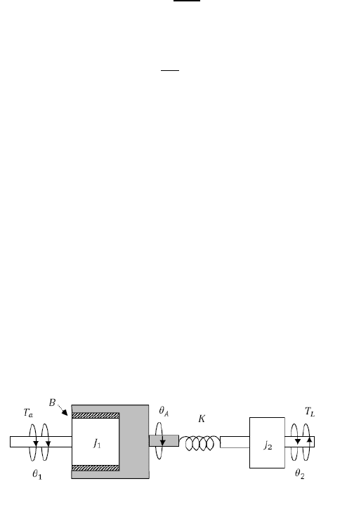
Derive the dynamic equations corresponding to the rotational mechanical system
shown in fig. 2.19, with Ta(t) and TL(t) considered as input and θ1(t) and θ2(t)
considered as outputs of the system respectively, also drawing the corresponding
SIMULINK and SIMSCAPE modeling diagrams.
Fig. 2.19 Rotational mechanical system for example 2.4
Solution
Firstly, we draw the free-body diagram for each inertia (fig. 2.20)
2.4 Mechanical Systems 29
Fig. 2.20 Free-body diagrams for example 2.4
0
0
0
Solving
θ
A
(t) from the second equation and substituting in the rest, we obtain the
dynamic equations.
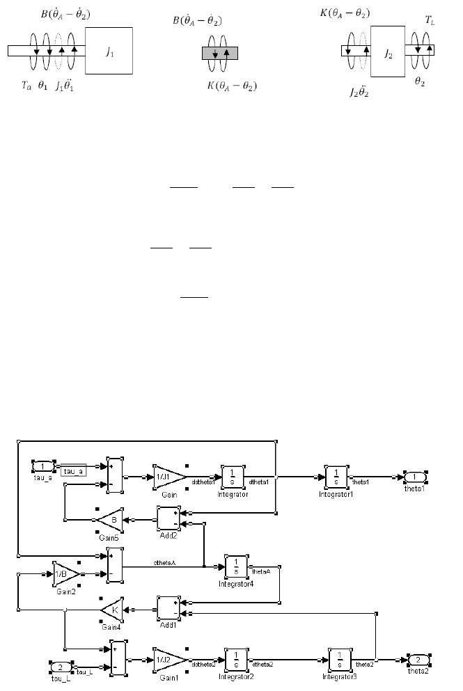
In fig. 2.21 and fig. 2.22 the corresponding modeling diagram developed by
using both the SIMULINK and SIMSCAPE environments are shown
Fig. 2.21 SIMULINK diagram corresponding to example 2.4
30 2 System Modeling
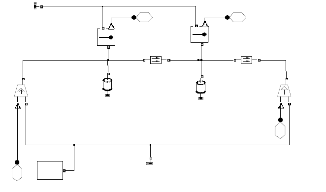
Fig. 2.22 SIMSCAPE diagram corresponding to example 2.4
2.5 Hydraulic Systems
The distributed nature and the nonlinear character of the resistance to flow makes
the obtaining of the dynamic equations for the hydraulic systems, difficult in
general. In fact, there may be two types of fluid regimes, laminar and turbulent,
characterized by linear and nonlinear dynamic equations, respectively.
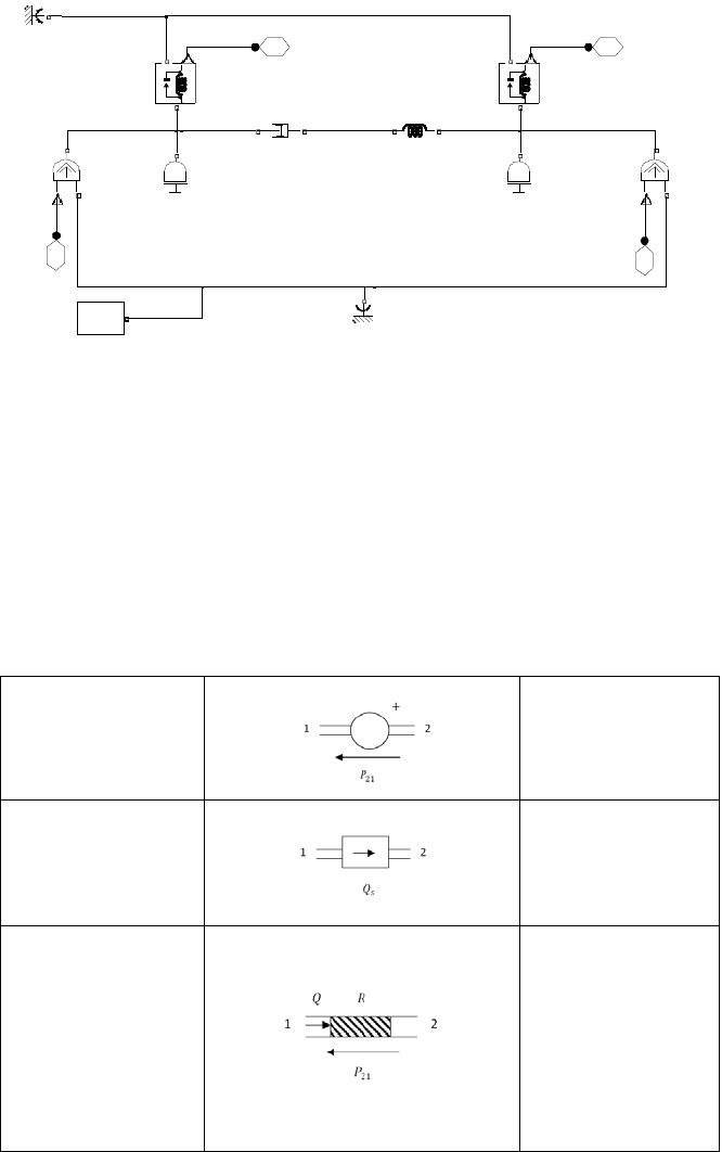
Table 2.7 Hydraulic elements and corresponding dynamic equations
Pressure
Source
Flow
Source
Hydraulic
Resistor
Laminar
Turbulent
Tau L 4
Tau a
3
Theta2
2
Theta1
1
Theta_2
R
C
T
Theta_1
R
C
T
Tau_a
S
C
R
Tau_L
S
C
R
Solver
f(x)=0
K
R
C
J2J1
Ground1
Ground
B
R
C
2.5 Hydraulic Systems 31
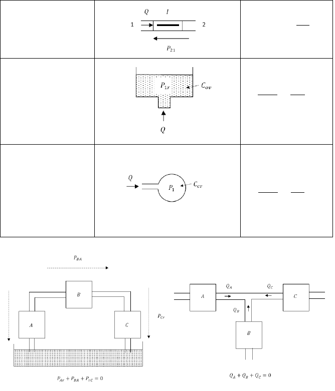
Table 2.7 (continued)
Hydraulic
Inertor
Hydraulic
Capacitor
(open vessel)
1
Hydraulic
Capacitor
(closed vessel)
1
Fig. 2.23 Conservation laws used to obtain the dynamic equations for hydraulic systems.
In order to derive the dynamic equations corresponding to fluid systems, we are
going to assume linear and lumped systems in general, made up of combinations
of ideal hydraulic elements.
In table 2.7 the main elements that appear at hydraulic systems translational
with its corresponding icons and dynamic equations are described.
The fluid conservation laws employed to obtain the complete set of equations
involving the hydraulic elements are the same corresponding to Kirchoff’s laws
already described. The compatibility law settles that the sum of pressure drops
32 2 System Modeling
around a loop must be equal to zero, while the continuity law states that the sum
of the flow rates at an hydraulic junction must be also zero (fig. 2.23).
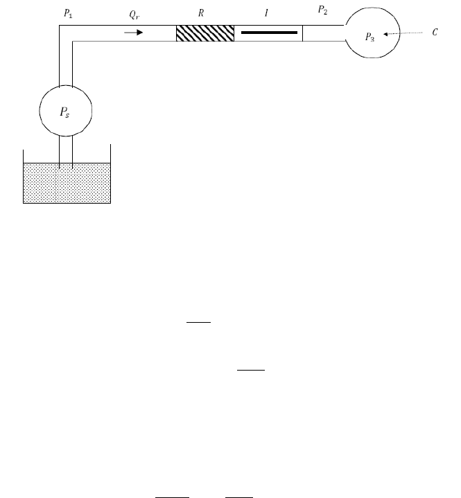
Example 2.5
Derive the dynamic equations corresponding to the hydraulic circuit shown in
fig. 2.24, with Ps(t) and P3r(t) considered as input and output of the system
respectively, also drawing the corresponding SIMULINK and SIMSCAPE
modeling diagrams.
Fig. 2.24 Hydraulic system for example 2.5
Solution
0
Solving for
in the second equation and substituting in the first one, yields
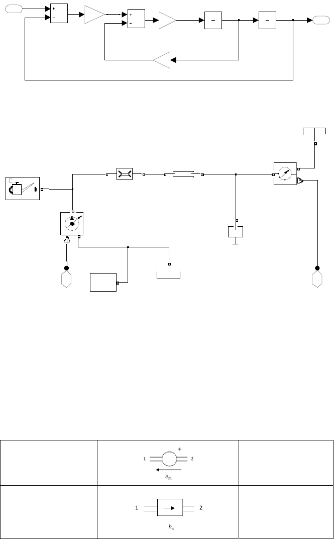
In fig. 2.25 and fig. 2.26 the corresponding modeling diagram developed by using
both the SIMULINK and SIMSCAPE environments are shown
2.6 Thermal Systems 33
Fig. 2.25 SIMULINK diagram corresponding to example 2.5
Fig. 2.26 SIMSCAPE diagram corresponding to example 2.5
2.6 Thermal Systems
The mathematical modeling of thermal systems is based on the fundamental laws
of the thermodynamics. Thermal systems are in general distributed, so that their
dynamic equations are expresses as partial differential equations. We will restrict
our analysis to lumped system and approximated linear behavior in general.
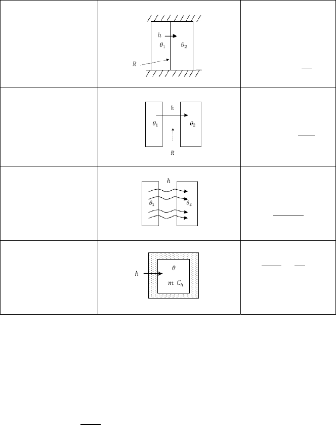
Table 2.8 Thermal elements and corresponding dynamic equations
Temperature
Source
Heatflow
Source
P3r
1
Subtract 1
Subtract
Integrator 1
1
s
Integrator
1
s
Gain 3
R
Gain 2
1/C
Gain 1
1/I
Ps
1
dP3r P3r
Ps
ddP3r
P3r 2Ps 1
Solver
f(x)=0
R
A
B
Ps
S
T
P
P3r
A
B
P
I
A
B
Ground
Fluid
C
34 2 System Modeling
Table 2.8 (continued)
Conductive
Thermal
Resistor
Convective
Thermal
Resistor
1
Radiation
Thermal
Resistor
1
Thermal
Capacitor (Mass)
1
In table 2.8 the main elements that appear at thermal systems with its
corresponding icons and dynamic equations are described.
The thermal conservation laws employed to obtain the complete set of
equations involving the thermal elements are the energy balance equations for
each thermal mass, considering the net heat input flow, net heat output flow and
heat flow generated, so that
(2.5)
Example 2.6
Derive the dynamic equations corresponding to the thermal circuit shown in
Fig. 2.27, with q(t) considered as input and θ1(t) and θ2(t) considered as output of
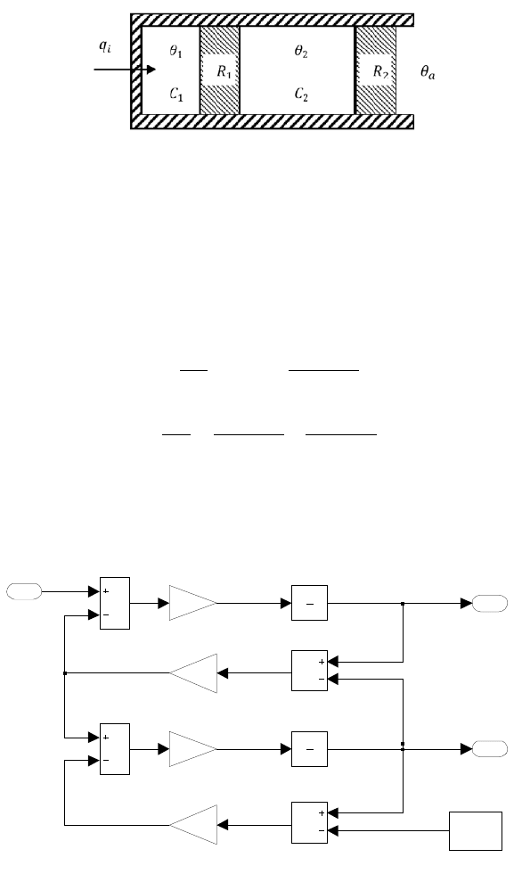
2.6 Thermal Systems 35
Fig. 2.27 Thermal system for example 2.6
the system respectively, also drawing the corresponding SIMULINK and
SIMSCAPE modeling diagrams.
Solution
In fig. 2.28 and fig. 2.29 the corresponding modeling diagram developed by using
both the SIMULINK and SIMSCAPE environments are shown
Fig. 2.28 SIMULINK diagram corresponding to example 2.6
theta _2
2
theta _1
1
Subtract 3
Subtract 2
Subtract 1
Subtract
Integrator 2
1
s
Integrator 1
1
s
Gain 4
1/R2
Gain 3
1/R1
Gain 2
-K-
Gain 1
-K-
Constant
theta_a
qi
1
theta1
qi
dtheta1
theta2dtheta2
36 2 System Modeling
Fig. 2.29 SIMSCAPE diagram corresponding to example 2.6
2.7 Hybrid Systems
Many dynamical systems consist of combinations of electric, mechanical, fluid,
and thermal systems, resulting in electromechanical, hydromechanical, and so on.
In order to derive the dynamic equations of the combined systems we have to
employ coupling devices to convert one kind of magnitude (electrical, mechanical,
etc.) to another. In this way, we are going to assume linear and lumped systems in
general, made up of combinations of ideal converters.
We will restrict our analysis to electromechanical and hydromechanical
converters, both of displacement and rotational types, and signal converting
transducers.
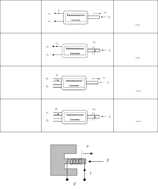
In table 2.9 the main converters that appear at electromechanical and
hydromechanical systems with its corresponding icons and dynamic equations are
described.
In each case, the coupling device converts one kind of energy to another
throughout a coupling coefficient
α
t
and D
t
for electromechanical and
hydromechanical converters respectively.
The electromechanical translational converter represents an electromagnet,
whose primary use is as an electric drive (fig. 2.30).
theta_a 4
qi 3
theta_2
2
theta_1
1
theta_a
S
A
B
theta_2
A
B
T
theta_1
A
B
T
qi
S
A
B
Solver
f(x)=0
R2
A
B
R1
A
B
Ground
C2
C1
2.7 Hybrid Systems 37
Table 2.9 Electromechanical and hydromechanical elements with corresponding dynamic
equations
Electromechanical
Translational
Converter
1
Electromechanical
Rotational
Converter
1
Hydromechanical
Translational
Converter
1
Hydromechanical
Translational
Converter
1
Fig. 2.30 Schematic of the electromagnet device.
The electromechanical rotational converter represents both an ideal DC motor
and an ideal DC generator, whose primary use is in DC electric circuits (fig. 2.31).