Czichos H., Saito T., Smith L.E. (Eds.) Handbook of Metrology and Testing
Подождите немного. Документ загружается.

408 Part C Materials Properties Measurement
7.5 Fracture Mechanics
In materials that are components of large engineering
structures the presence of fabrication flaws and their
development during operational service should be an-
ticipated. It is rational to assume that flaws exist and
that countermeasures against the fracture and fatigue
that develop from them should be taken.
In the 1920s, A. A. Griffith conducted a series of
experiments to determine the fracture strength of glass
components that contained small flaws. From this ex-
periments, he concluded that for brittle materials the
stress required to cause failure decreased as the size
of the flaw increased, even after correction is made
for the reduced cross section of good material. Extend-
ing these findings to other types of materials, it was
generally found that the strength of a structural compo-
nent that contains a crack or crack-like flaw decreases
with increasing crack size and cannot be deduced
from the mechanical properties obtained in conven-
tional tensile tests (Sect. 7.3.1) or other mechanical tests
using smooth specimens. The combined mathematical–
experimental approach employed in the evaluation of
the strength of cracked components is called fracture
mechanics; it provides a metodology to determine the
amount of crack growth and the residual strength of
cracked components during operational service.
7.5.1 Fundamentals of Fracture Mechanics
The fundamental principle of fracture mechanics is that
the stress and strain field ahead of a sharp crack can be
characterized in terms of a single parameter, such as the
stress intensity factor K , that is a function of the applied
stress, crack size and geometrical boundary conditions.
Crack growth or fracture initiation from a precrack must
be controlled by the stress or strain state at the crack–
tip region. This implies that the fracture behavior from
a crack can be described by the fracture mechanics pa-
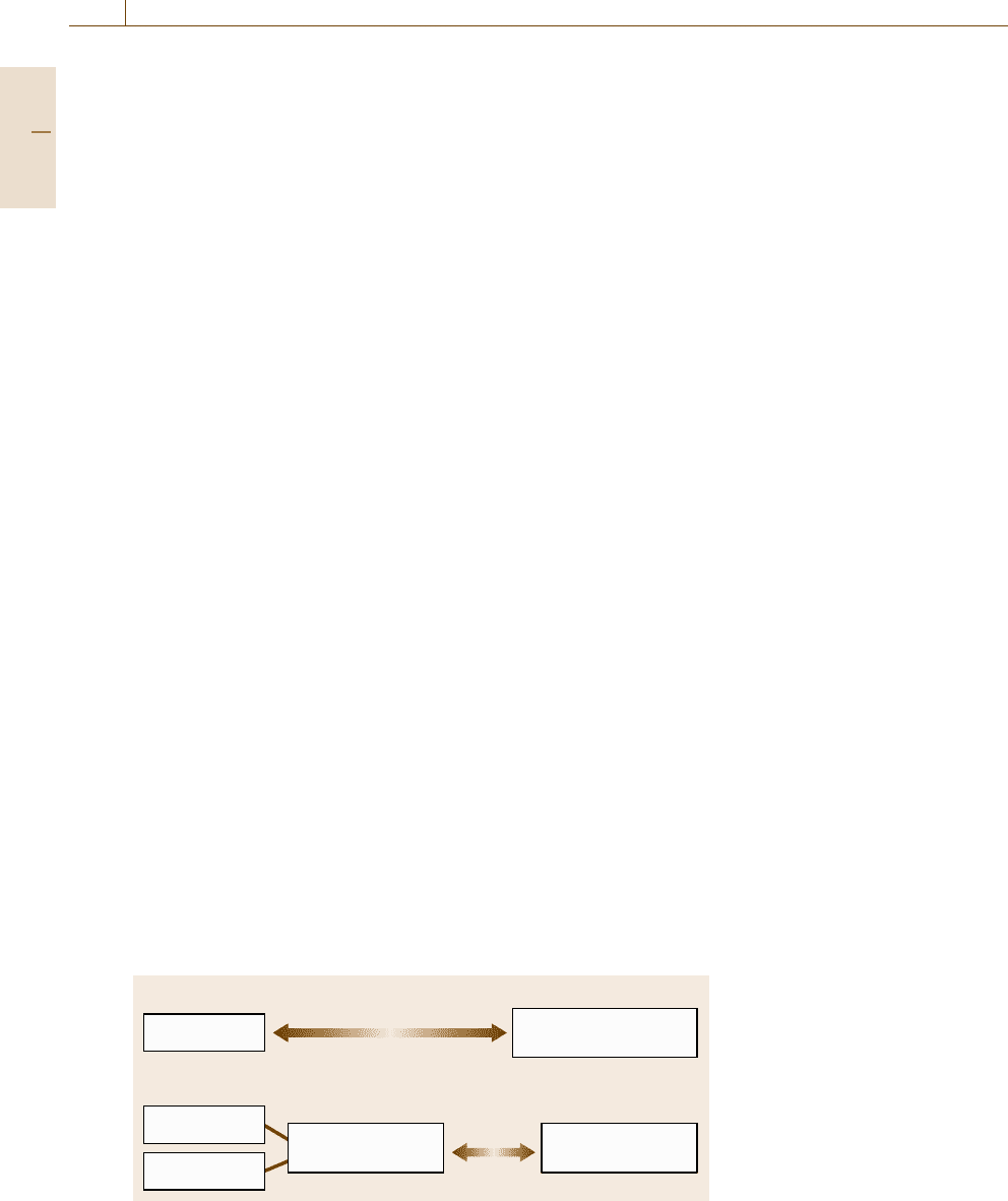
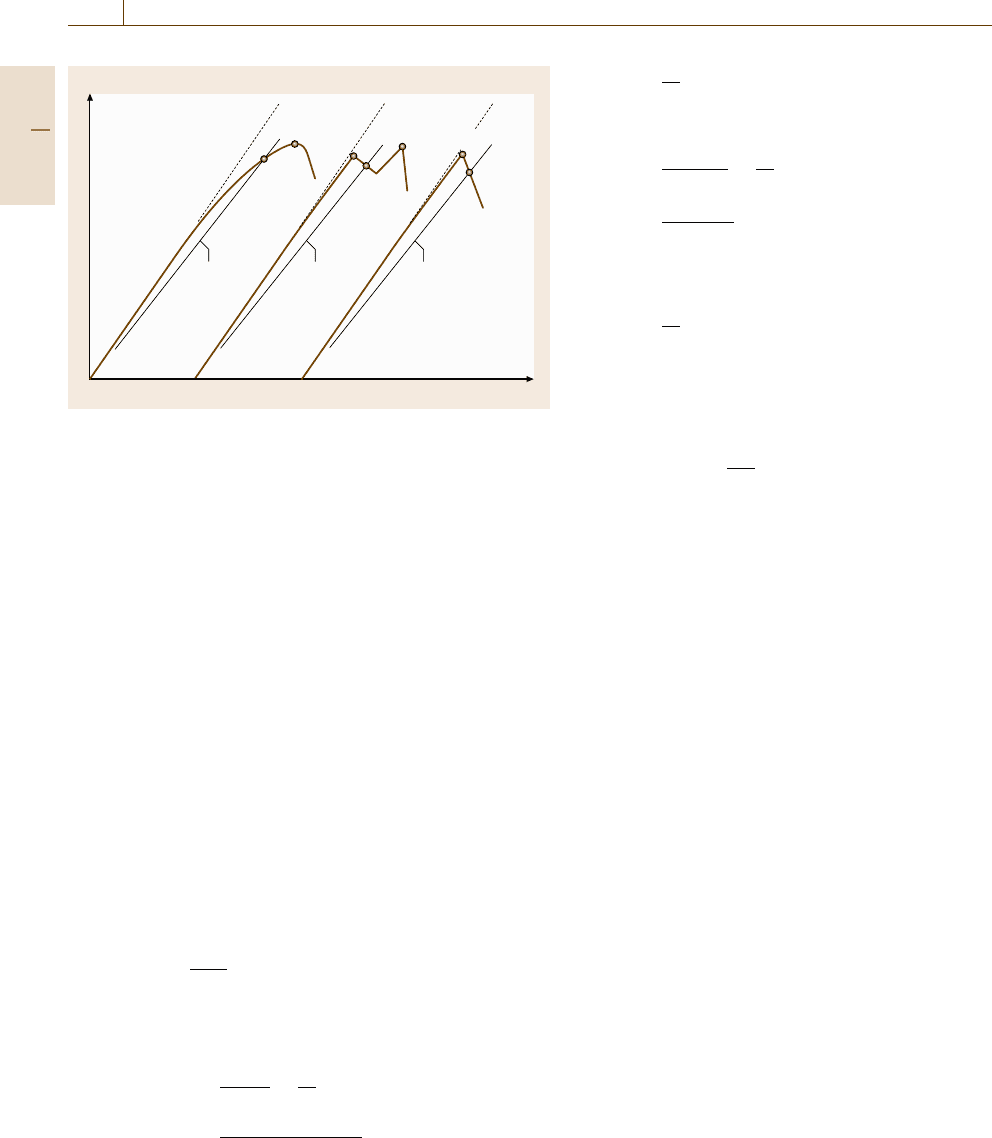
Applied stress
Applied stress
Flaw size
Fracture mechanics
parameter
Fracture resistance
of material
Yield or tensile strength
of material
a)
b)
Fig. 7.72a,b Comparison of the frac-
ture mechanics approach
(b) to design
with the (a) traditional design ap-
proach
rameter, as an analogy with the plastic yielding behavior
of materials described in the form of σ
eq
(equivalent
stress) =σ
ys
(yield strength of the material). The crack–
tip stress–strain similarity anticipates to result in the
same type of fracture under the same environmental
condition. Once the fracture resistance of a material is
described in terms of its fracture mechanics parameter
in laboratory tests, one can deduce its fracture behavior
under different applied stresses, crack sizes and geo-
metrical boundary conditions without any discussion of
the mechanisms of fracture concerned. The fracture me-
chanics approach has three variables for the evaluation
of strength, as shown in Fig. 7.72.
Fracture mechanics can be subdivided into two gen-
eral categories, namely linear elastic and elastic–plastic.
Materials with relatively low fracture resistance fail
under small-scale yielding at the crack tip and can
be analyzed through linear-elastic fracture mechanics
(LEFM), in which the stress intensity factor, K, is based
on the elastic stress analysis. Metallic materials of-
ten show large-scale plastic yielding preceding crack
growth or fracture initiation from the crack. Elastic–
plastic fracture mechanics (EPFM) is applied for these
large-scale yielding conditions. The J integral and the
crack–tip opening displacement (CTOD) can be used as
alternative fracture mechanics parameters to K.
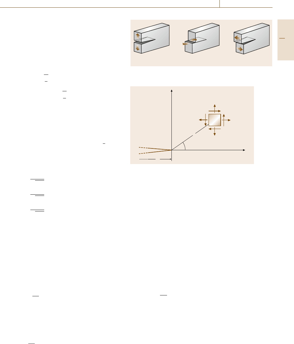
Linear Fracture Mechanics
Consider an elastic body of arbitrary configuration
with an ideally sharp crack, subjected to arbitrary
external forces. There are three types of relative move-
ments of the two crack surfaces, as Fig. 7.73 illustrates.
The opening mode, mode I, is the most popular
displacement mode in practical components, and is
characterized by opening displacements in the direction
of the principal load. Mode II and mode iII correspond
to in-plane shear loading and out-of-plane shear load-
Part C 7.5
Mechanical Properties 7.5 Fracture Mechanics 409
ing, respectively. In any problem a cracked body can be
treated as one or a combination of these three modes.
The theory of elasticity derives closed-form expres-
sions for the stresses around the crack tip for each of
these modes of deformation, assuming isotropic linear
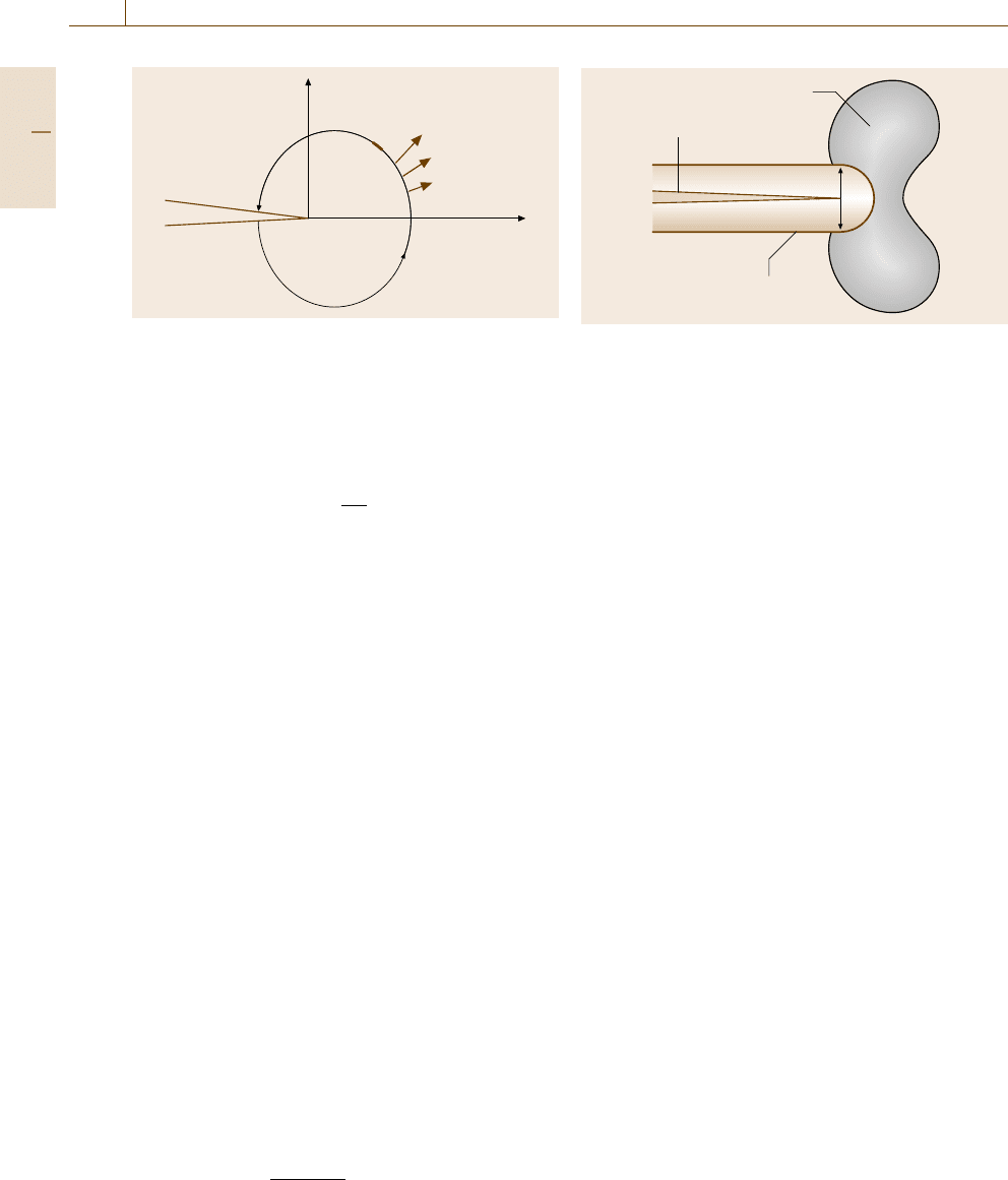
elastic material behavior [7.228–230]. For a polar coor-
dinate axis as shown in Fig. 7.74, the stress field in any
cracked body is given by
σ
ij
(r,θ) =
k
a
r
f
ij
(θ)
+
∞
n=0
A
n
r
a
n
g
ij,n
(θ) , (7.78)
where σ
ij
is the stress tensor, k and A
n
are constants,
and f
ij
and g
ij
are functions of θ. The higher-order
terms depend on the geometrical boundary conditions.
The first leading term approaches infinity as r reaches 0,
but the other terms remain finite. Thus, the stress at the
crack–tip region has a singularity of order 1/
√
r, regard-
less of the configuration of the cracked body. The stress
fields ahead of a crack tip, where r is sufficiently small
compared with the crack length a, can be rewritten as
σ
ij
, I =
K
I
√
2πr
f
ij,I
(θ) , (7.79a)
σ
ij
, II =
K
II
√
2πr
f
ij,II
(θ) , (7.79b)
σ
ij
, III =
K
III
√
2πr
f
ij,III
(θ) , (7.79c)
for modes I, II, and III, respectively. These field equa-
tions show that the magnitude of the elastic stress field
can be described by the single-term parameters K
I
, K
II
,
and K
III
. The stress intensity factor K, given a subscript
to denote the mode of crack deformation, is a func-
tion of the applied force, the crack shape and size,
and the structural configuration. However, since mode I
cracking is often question in practical constructions, the
subscript I is usually abbreviated for the mode I.
The general form of the stress intensity factor is
given by
K = Fσ
√
πa , (7.80)
where F is a parameter that depends on the geome-
try of the specimen or component with a crack. For an
infinite plate subjected to uniform tensile stress σ con-
taining a through-thickness crack of length 2a, the stress
intensity factor is
K =σ
√
πa . (7.81)
a) b) c)
Fig. 7.73a–c Three modes of crack deformation. (a) Mode I (open-
ing) (b) Mode II (in-plane shear) (c) Mode III (out-of-plane shear)
y
σ
yy
σ
xx
τ
yx
τ
yx
r
θ
a
x
Fig. 7.74 Crack–tip stresses in polar coordinate
Equations (7.79aa–c) show the elastic stress field in the
singularity zone ahead of the crack for an idealized
crack model. In real materials, the stresses at the crack
tip do not take an infinite value because the crack–tip
radius must be finite, and the metallic material in this
region undergoes plastic deformation and leads to fur-
ther relaxation of the crack–tip stress. However, the size
of the plastic zone or the ambiguity zone that surrounds
the crack tip is so small compared with the singular-
ity zone (for small-scale yielding) that the stresses in
the surrounding zone still take the form (7.79a). Thus,
the stress intensity factor K is still a representative pa-
rameter for the stress field at the crack tip, although the
crack–tip stresses are devoured in black box.
The small-scale yielding condition is given by the
ASTM [7.231]as
a ≥2.5
K
σ
ys
2
, (7.82)
which gives one of the limitations for linear elastic frac-
ture mechanics.
Elastic–Plastic Fracture Mechanics
Under the large-scale yielding condition, where (7.82)
is not satisfied, the stress intensity factor loses its
physical basis as a fracture mechanics parameter. An al-
Part C 7.5
410 Part C Materials Properties Measurement
y
T
i
,u
i
ds
x
Γ
Fig. 7.75 Contour integral around the crack tip
ternative parameter for a nonlinear elastic material is the
J integral. Rice [7.232] presented a path-independent
contour integral, which is called J, for a cracked body.
The J integral is given by
J =
Γ
W(ε
ij
)dy −T
i
∂u
i
∂x
ds
(7.83)
where W(ε
ij
) is the strain energy density, T
i
are
the components of the traction vector, u
i
are the
components of the displacement vector, and ds is
a length increment along the contour Γ , as illustrated
in Fig. 7.75.
The value of the J integral is independent of the path
of integration and is equivalent to the energy-release
rate for a nonlinear elastic material. It can be shown
that the J integral characterizes the crack–tip stress field
in a nonlinear elastic material (the Hutchinson–Rice–
Rosengren (HRR) stress field) [7.233, 234]aswellas
the stress intensity factor in a linear elastic material.
Under the large-scale yielding condition, the size of the
HRR stress field depends on the magnitude of the plastic
yielding scale and the plastic constraint of a speci-
men. Whether the HRR stress field exists or not gives
a limitation on the J integral approach for large-scale
yielding [7.235].
Another parameter in elastic–plastic fracture me-
chanics is the crack–tip opening displacement (CTOD),
the plastic deformation blunted an initially sharp crack,
as illustrated in Fig. 7.76. Wells [7.236] proposed the
opening at the crack tip as a measure of fracture tough-
ness. The CTOD can be related to the stress intensity
factor and the J integral under the small-scale yielding
condition as given by
J = mδσ
ys
=
K
2
E(1−ν
2
)
, (7.84)
Plastic zone
Initial crack
Blunted crack
δ
Fig. 7.76 Crack–tip blunting and CTOD
where δ is the CTOD, m is a dimensionless constant
that depends on material properties and stress triaxiality,
and E and ν are the elastic modulus and Poisson’s ratio,
respectively.
Details of the J integral and CTOD are well
described in [7.235]. To evaluate the J integral accord-
ing to (7.83), numerical analysis with a constitutive
equation for the material (relationship between plastic
strain and stress) is needed. The CTOD has an am-
biguity in its definition for numerical analysis. Thus,
the evaluation of parameters during the application
of the elastic–plastic fracture mechanics for actual
structures is difficult. For a deeply cracked specimen
subjected to bending load, simple experimental proce-
dures have been proposed to evaluate the J integral and
CTOD [7.235,237, 238].
7.5.2 Fracture Toughness
The fracture mechanics parameter uniquely stipulates
the stress and strain state at the crack tip provided that
the constraint in a direction parallel to the crack front is
the same. The constraint on deformation in the crack–
tip region is closely related to the triaxial stress state and
depends on the geometry of the specimen, the scale of
plastic yielding, and strain hardening of the material.
Linear elastic fracture mechanics describes unsta-
ble fracture as fracture occurs when the stress intensity
factor K reaches a critical value K
c
. The fracture
toughness, K
c
for mode I deformation under small-
scale yielding and plane–strain stress state (sufficient
constraint), is designated K
Ic
[7.231]. The toughness
in terms of the J integral is designated by J
Ic
and
J
c
[7.237]. J
Ic
is the toughness for onset of slow crack
growth from a crack and J
c
is the toughness for un-
stable fast fracture. It should be noted that there is
no harmonization in terminology of K
Ic
and J
Ic
. The
Part C 7.5
Mechanical Properties 7.5 Fracture Mechanics 411
CTOD criterion is also applied to evaluate the fracture
toughness under large-scale yielding. Historically, the
cleavage fracture toughness of structural steels has often
been evaluated in terms of the critical CTOD δ
c
.
In the standards for toughness testing, several spec-
ifications are prescribed so that the constraint effect
can be negligible. Single-parameter fracture mechanics
breaks down in the presence of excessive plasticity, or
for specimens with too shallow a notch, and fracture
toughness depends on the size and geometry of the test
specimen.
K
Ic
Testing
The standard test methods for determining plane–strain
fracture toughness (K
Ic
) of metallic materials are spec-
ified in several standards [7.231, 238, 239]. In these
standards, ASTM E399-90 [7.231], which was origi-
nally published as E399-70, is widely used.
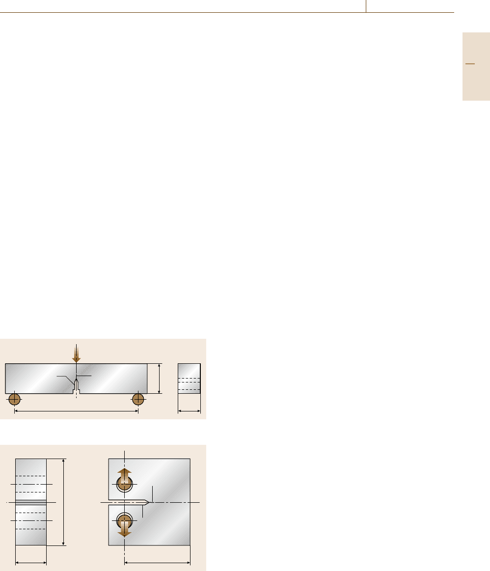
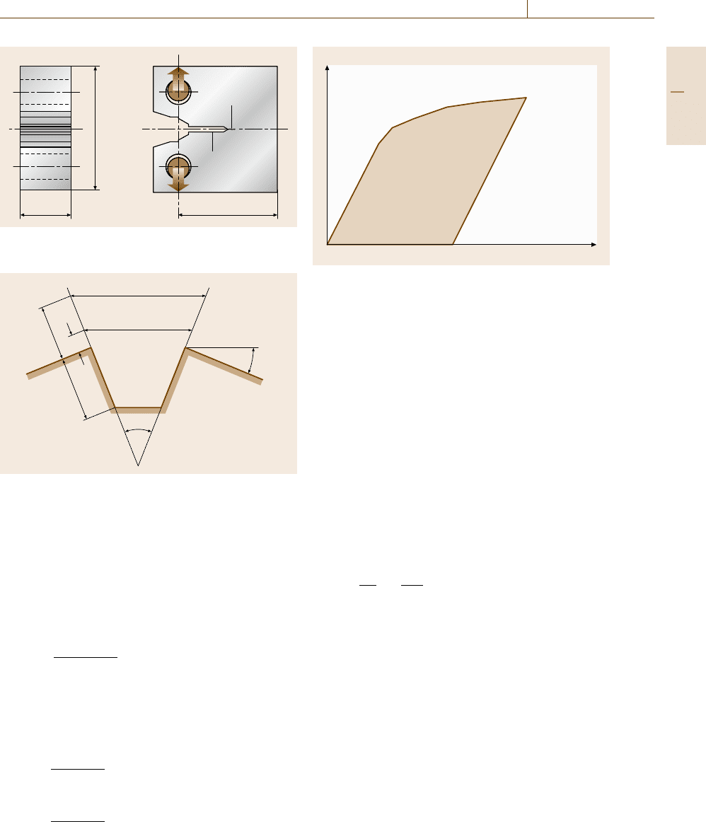
For the standard K
Ic
test, a single-edge notched
(SEN) bend specimen or a compact test (CT) spec-
imen is used; these standard geometries are shown
in Figs. 7.77 and 7.78, respectively. The standard
bend specimen has a rectangular cross section (B ×2B,
W =2B, where B is the specimen thickness and W is
the specimen width). Alternative a specimen geometry
with square cross section (B × B, W = B) can also be
used for the bend test. However, the size requirement for
Notch
Fatigue
precrack
S B
W
Fig. 7.77 Single-edge notched (SEN) bend specimen
Fatigue
precrack
Notch
1.2 W
B
W
Fig. 7.78 Compact test (CT) specimen
the plane–strain fracture toughness test, which will be
described later, should be satisfied. In the CT specimen,
W = 2B is recommended.
The fatigue precrack is introduced at the notch tip
by cyclic loading and the recommended value for the
total crack length (machined notch plus fatigue crack)
is 0.45–0.55W. The fatigue precracking load can af-
fect the fracture toughness results, so the cyclic loading
conditions are strictly limited. The stress ratio (min-
imum load to maximum load) of cyclic loading is
between −1and0.1. The maximum fatigue stress in-
tensity (K
max
) does not exceed 80% of the K
Ic
value of
the material. For the final stage of fatigue crack exten-
sion, K
max
must not exceed 60% of the K
Ic
value, and
the ratio of K
max
to the Young’s modulus of the material
K
max
/E should not exceed 0.00032 m
1/2
. Usually, the
number of cycles for fatigue precracking is 10
4
–10
6
.
Normally, as the temperatures of the fatigue cracking
and fracture toughness tests are different, the effect of
temperature should be taken into account. When fatigue
cracking is conducted at temperature T
1
and the frac-
ture testing at a different temperature, T
2
, K
max
must
not exceed 0.6(σ
ys1
/σ
ys2
)K
Ic
, where σ
ys1
and σ
ys2
are
the yield stress at the respective temperatures T
1
and T
2
.
It is recommended that the length of the fatigue crack be
larger than 1.3mmand2.5% of W for a straight-through
notch.
The single-edge notched specimen is loaded in
three-point bending with a support span S, which is nor-
mally equal to 4W,thatisS =4W. The bend testing
fixture is designed to minimize friction effects by allow-
ing the support rollers to rotate and move apart slightly
when the specimen is loaded. The compact specimen is
loaded in tension through pins by allowing the specimen
to rotate during the test.
Fracture tests are conducted with a static load-
ing with a rate of increase of stress intensity of
0.55–2.75 MPa m
1/2
. The test temperature is controlled
within 3
◦
C[7.237] and the specimen should be kept at
the test temperature for 1.2min/mm of specimen thick-
ness before testing [7.238]. During testing, continuous
measurement of load versus crack mouth opening dis-
placement is required. The displacement is measured
by a double-cantilever displacement gage or a ring-type
displacement gage.
After fracture testing, the crack length is measured
at the following three positions: at the crack front, and
midway between the center of the crack front and the
end of the crack front on each surface of the speci-
men. The average of these three measurements is the
crack length and is used to calculate the stress intensity.
Part C 7.5
412 Part C Materials Properties Measurement
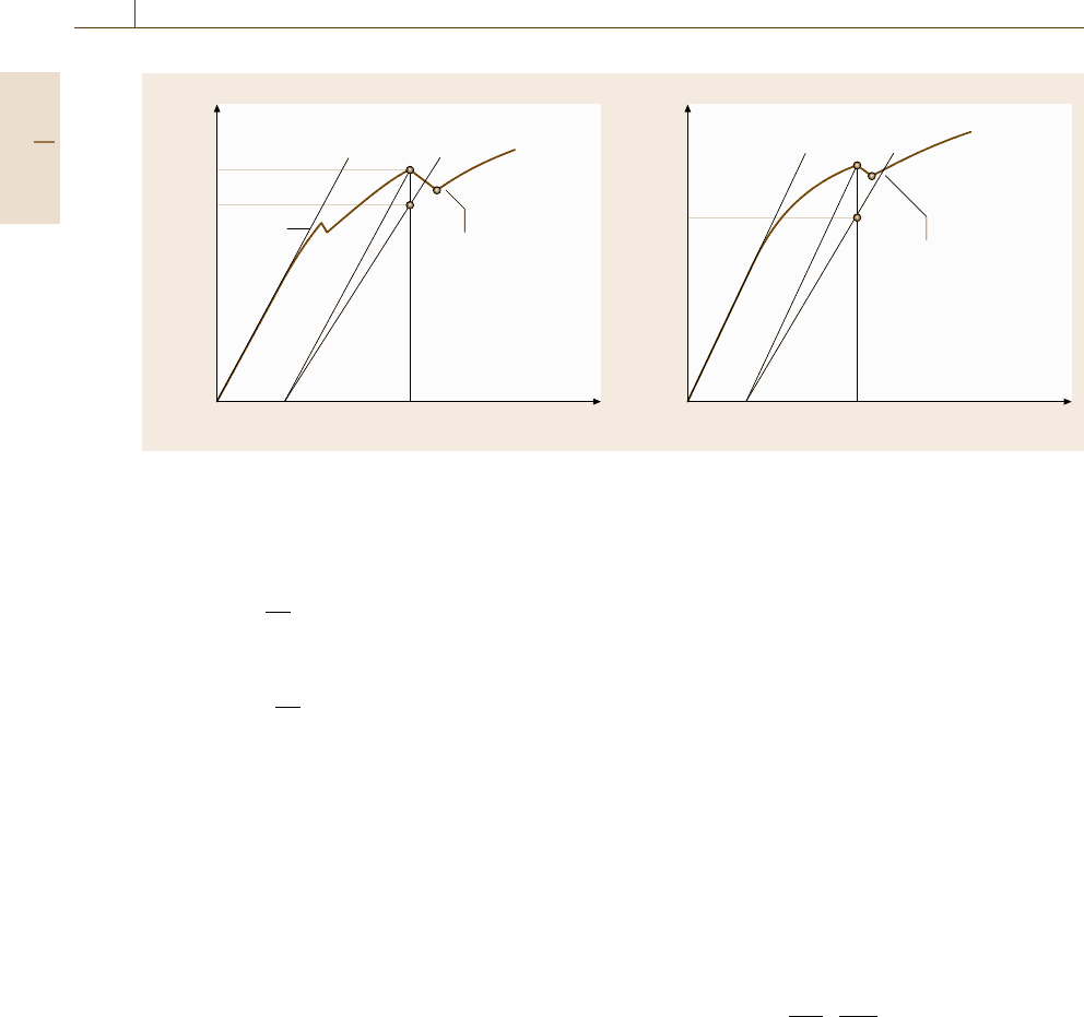
Load P
000
Type I Type II Type III
95%
Secant
95%
Secant
95%
Secant
Displacement V
A
A
A
P
max
P
max
P
max
–P
Q
P
5
P
Q
P
5
P
Q
–P
5
Fig. 7.79 Principal types of load–displacement records
The maximum difference between these measurements
is specified in the standards.
Based on the test record of load versus crack mouth
opening displacement, it is first necessary to calculate
a conditional result K
Q
, using which the size require-
ment for the plane–strain condition is judged. When
the size requirement is satisfied K
Q
becomes K
Ic
. The
procedure is as follows
1. Draw the secant line OP
5
from the origin of the
record with the slope (P/V )
5
=0.95(P/V)
o
, where
(P/V)
o
is the slope of the tangent OA to the initial
linear part of the test record, as shown in Fig. 7.79.
The load P
Q
is then defined as follows: if the load
at every point on the record which precedes P
5
is
lower than P
5
,thenP
5
is P
Q
(Fig. 7.79, type I); if,
however, there is a maximum load preceding P
5
that
exceeds it, then this maximum load is P
Q
(Fig. 7.79,
types II and III).
2. Calculate the ratio P
max
/P
Q
, where P
max
is the
maximum load of the record. If this ratio does not
exceed 1.10, that is,
P
max
P
Q
≤1.10 (7.85)
then, proceed to calculate K
Q
.
For an SEN bend specimen,
K =
PS
BW
1.5
f
a
W
,
f (x) =
3x
0.5
2(1 +2x)(1 −x
1.5
)
×
1.99−2.15x +6.08x
2
−6.83x
3
+2.07x
4
,
x =
a
W
. (7.86)
For a CT specimen,
K =
P
BW
0.5
f
a
W
,
f (x) =
2 +x
(1 −x)
1.5
×
0.886+4.64x −13.32x
2
+14.72x
3
−5.60x
4
,
x =
a
W
. (7.87)
3. Calculate 2.5(K
Q
/σ
ys
)
2
, where σ
ys
is the yield
stress of the material at the test temperature. If the
following is satisfied, then K
Q
is equal K
Ic
.
B, a ≥ 2.5
K
Q
σ
ys
2
. (7.88)
4. If the test results fails to meet the requirements
in (7.80)orin(7.81), or both, it is necessary to use
a lager specimen to determine K
Ic
.
J
c
, J
u
Testing
When the specimen size is inadequate to meet the re-
quirement given by (7.88), a valid K
Ic
value is not
obtained. The reason for this is that the plastic deforma-
tion in the specimen is too large to meet the plane–strain
condition. In such case, an alternative method is to
use elastic–plastic fracture mechanics. The J integral
is one such parameters, which is a line or surface
integral enclosing the crack front from one crack sur-
face to the other, and is used to characterize the local
stress–strain field around the crack tip. The method
for determining fracture toughness at the fracture in-
stability based on the J integral is described in the
standards [7.237, 238, 240], of which ASTM E1820-
01 [7.237] covers the procedures and guidelines for the
determination of the fracture toughness using fracture
parameters such as K, J, CTOD (δ). The original J
Ic
and J–R test methods were developed in the original
ASTM E813-81 [7.241] and E1152-87 [7.242], respec-
tively. Theses test methods are now unified in E1820.
When fracture instability occurs before stable tear-
ing the fracture toughness, labeled J
c
, is obtained.
When the instability occurs after stable tearing the frac-
ture toughness is denoted by J
u
.InJ
c
and J
u
testing, the
standard specimen for K
Ic
testing is applicable. How-
ever, in order to calculate J, it is necessary to record
the curves of load versus load-line displacement. For
Part C 7.5
Mechanical Properties 7.5 Fracture Mechanics 413
Fatigue
precrack
Notch
1.2 W
B
W
Fig. 7.80 Compact test (CT) specimen for the J integral
test
V
2
V
1
z
1
z
2
a
θ
θ/2
Fig. 7.81 Double-clip gage method for determining load-
line displacement of the SEN bend test
CT test, the load-line displacement is directly measured
by using the specimen shown in Fig. 7.80.FortheSEN
bend test, special care must be paid to indentation of
the specimen by the loading jig. One possible method
for measuring the load-line displacement is to use dou-
ble clip gages. The load-line displacement V
L
may be
calculated by (Fig. 7.81)[7.238]
V
L
=
W(V
2
−V
1
)
z
2
−z
1
. (7.89)
For fatigue precracking, the maximum load should be
less than
P
max
≤ P
f
. (7.90)
P
f
is given by
P
f
=
0.5Bb
o
σ
Y
S
(7.91)
for the SEN bend specimen. For the CT specimen,
P
f
=
0.4Bb
o
σ
Y
2W +a
o
, (7.92)
Load P
Original slope
Load-line displacement V
L
Area A
pl
Fig. 7.82 Definition of area for the J calculation
where, b
o
= W −a
o
(initial ligament depth) and σ
Y
is
the flow stress given as the average of the yield stress,
σ
ys
and the tensile strength σ
uts
. The condition (7.90)
is equivalent to limiting the maximum stress intensity,
K
max
of fatigue precracking, according to
K
max
≤0.47σ
Y
B
0.5
. (7.93)
From the fracture instability point, the critical load P
Q
is determined. The J-integral value J
Q
corresponding
to P
Q
is calculated using
J = J
el
+ J
pl
, (7.94)
where J
el
is the elastic component of J and J
pl
is the
plastic component of J. At a point corresponding to V
L
and P on the specimen load versus load-line displace-
ment, J is calculated through
J =
K
2
E
+η
A
pl
Bb
o
, (7.95)
where, η =2fortheSEN bend, and η =2+0.522b
o
/W
for the CT method. E
=(1−ν
2
)/E,andA
pl
is the area
showninFig.7.82.
After testing, along the front of the fatigue crack and
the front of the stable crack extension (if it exists), mea-
sure the size of the original crack and the final physical
crack size at nine equally spaced points centered about
the specimen centerline and extending to 0.005W from
the specimen surface. The original crack size a
o
and
the physical crack size a
p
are calculated by averaging
the two near-surface measurements and the remaining
seven crack-length measurements. The crack extension,
Δa
p
is calculated as a
o
−a
p
.
If Δa
p
< 0.2mm+J
Q
/2σ
Y
, the fracture instability
point corresponds to instability before stable tearing.
Part C 7.5
414 Part C Materials Properties Measurement
Load P Load P
P
c
or P
u
0.95 BD
0.95 BD
0C D 0C D
Clip gage displacement V
g
Clip gage displacement V
g
Pop-in
that may
NOT
be ignored
Pop-in
that may
be ignored
Previously
ignored
pop-in
A
A
BB
F
F
G
G
E
E
a)
b)
Fig. 7.83a,b Procedure for evaluating the significance of pop-in
For a ferritic steel with 250 MPa <σ
ys
< 725 MPa and
250 MPa <σ
uts
< 725 MPa for the room temperature
strength of the material,
B, b
o
≥50
J
Q
σ
Y
, (7.96)
and for other metallic materials,
B, b
o
≥100
J
Q
σ
Y
, (7.97)
where J
Q
becomes J
c
. It should be noted that, even if
these conditions are met, J
c
might depend on thickness.
If Δa
p
> 0.2mm+ J
Q
/2σ
Y
, the fracture instability
point corresponds to instability after stable tearing and
J
Q
becomes J
u
. This is a characteristic of the material
and specimen geometry and size.
When the material is heterogeneous, pop-ins are
sometimes observed in the record. If the pop-in is at-
tributed to an arrested fracture instability in the plane of
the fatigue crack, the result is considered to be a charac-
teristic of the material tested. Pop-in can be assessed
by a specific change in compliance, and also post-
test examination of the fracture surfaces. Pop-ins are
only evaluated when the load rises with increasing dis-
placement after pop-in, otherwise it is considered to be
a fracture instability.
The following procedure is used to assess the signif-
icance of pop-ins when post-test examination indicates
that they are associated with arrested fracture insta-
bility in the plane of the fatigue precrack. As shown
in Fig. 7.83: (1) draw a line CB which is parallel to the
initial slope OA and passes through the pop-in point un-
der consideration. (2) Draw a line CF with a slope 5%
less than the line CB. (3) Mark the point G, correspond-
ing to the load and displacement at pop-in. (4) When
the point G is within the angle BCF, the pop-in is
judged to be insignificant (Fig. 7.83b). (5) When the
point G is outside the angle BCF, the pop-in is signifi-
cant (Fig.7.83a). The judgment of (4) and (5) is whether
the arrested crack is more than 0.02 of the crack length
or not.
J–R Curve Testing
The J–R curve shows resistance of a material to stable
crack extension in terms of the J integral and consists
of a plot of J versus crack extension. The standard test
method of ASTM E1820-01 [7.237] is to use a single-
specimen technique with partial unloading using an
elastic-compliance method to determine the stable crack
extension. The maximum J integral capacity of a spec-
imen J
max
and the maximum crack extension capacity
for a specimen Δa
max
are given by the following
J
max
=min
bσ
Y
20
,
Bσ
Y
20
, (7.98)
Δa
max
=0.25b
o
. (7.99)
In J–R testing, SEN and CT specimens are used, usu-
ally with side groove. Here, the net thickness is denoted
by B
N
and the effective thickness is expressed by
B
e
= B −(B −B
N
)
2
/B. The J–R curve is constructed
by plotting J integral values versus the correspond-
ing crack extension values, as shown in Fig. 7.84. The
unload/reload sequences are spaced at load-line dis-
placement intervals of about 0.005W. The J integral
Part C 7.5
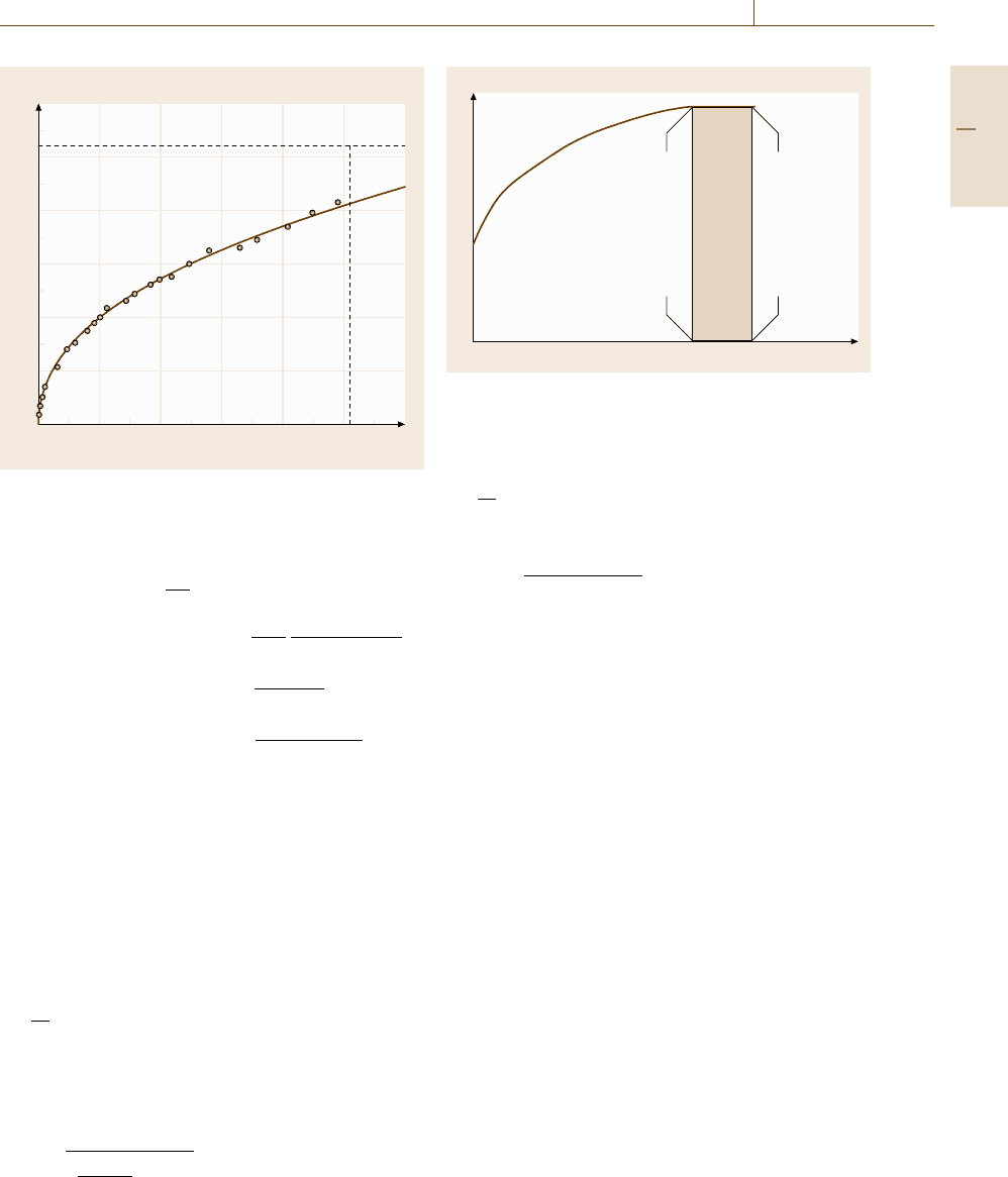
Mechanical Properties 7.5 Fracture Mechanics 415
J (kJ/m
2
)
600
500
400
300
200
100
0
0123456
Crack extension (mm)
J
max
Δa
max
Fig. 7.84 Typical J–R curve
values are calculated by
J
i
=
K
2
i
E
+ J
pl,i
, (7.100)
J
pl,i
=
J
pl, j−1
+
η
i−1
b
i−1
A
pl,i
− A
pl,i−1
B
N
×
1 −γ
i−1
a
i
−a
i−1
b
i−1
, (7.101)
A
pl,i
− A
pl,i−1
=
P
i
+P
i−1
V
pl,i
−V
pl,i−1
2
,
(7.102)
where, for SEN specimens η
i
=2andγ
i
=1, and for
CT specimens η
i
=2.0 +0.522b
i−1
/W and γ
i
=1.0 +
0.76b
i−1
/W. The quantity A
pl,i
− A
pl,i−1
in (7.102)is
the increment of plastic area under the load versus
load-line displacement record between lines of constant
displacement at points i −1andi, as shown in Fig. 7.85.
Using an elastic-compliance technique on an SEN
specimen with crack mouth opening displacement the
crack length is given as
a
i
W
=1.000−3.950u
+2.982u
2
−3.214u
3
+51.52u
4
−113.0u
5
,
(7.103)
where
u =
1
B
e
WEC
i
S/4
0.5
+1
.
(7.104)
Load P
Plastic load-line displacement V
L, pl
P
i-1
P
I
V
L, pl, i-1
V
L, pl, i
Fig. 7.85 Definition of area for the J calculation
For CT specimens, the crack length is determined using
the load-line displacement as
a
i
W
=1.000+4.063u +11.24u
2
−106.0u
3
+464.3u
4
−650.7u
5
, (7.105)
u =
1
EC
i
B
e
0.5
+1
. (7.106)
J
Ic
Testing
The property J
Ic
characterizes the toughness of a ma-
terial near the onset of crack extension from a fa-
tigue precrack. Originally, the J
Ic
test was specified
in ASTM E813 [7.241] and is now unified in ASTM
E1820 [7.237]. E1820-01 gives two methods to deter-
mine J
Ic
: the basic procedure and the resistance curve
procedure. The basic procedure involves physical mark-
ing of the crack extension and multiple (more than five)
specimens, which are used to develop a plot from which
an initiation toughness value is evaluated. The resis-
tance curve procedure is to determine the J
Ic
value from
the J–R curve, which is an elastic-compliance method
where multiple points are determined from a single spec-
imen.
In the basic procedure, five or more specimens are
used. After unloading the specimen, the crack is marked
by heat-tinting at about 300
◦
C (for steels and titanium
alloys) or fatigue cracking, and then, cooling and break-
ing the specimen. The physical crack size a
p
is then
measured at nine equally spaced points along the front
of the marked region of stable crack extension. The crack
extension Δa is calculated with
Δa =a
p
−a
o
. (7.107)
Part C 7.5
416 Part C Materials Properties Measurement
J (kJ/m
2
)
800
600
400
200
0
0 0.5 1.0 1.5 2.0 2.5
Crack extension (mm)
1.5 mm exclusion line
0.2 mm offset line
0.15 mm
exclusion line
Construction
line
Points used for
regression analysis
Power law regression line
J
o
J
limit
1
1
Mσ
Y
Mσ
Y
Δa
min
Δa
min
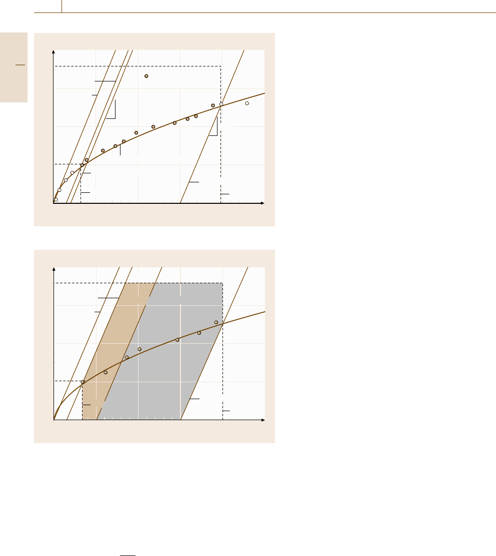
Fig. 7.86 Definition of construction line for data qualification
J (kJ/m
2
)
800
600
400
200
0
J
o
J
limit
Region of qualified data
BA
0.15 mm
exclusion line
Construction
line
0
0.5 1.0 1.5 2.0 2.5
Crack extension (mm)
1.5 mm exclusion line
Δa
min
Δa
min
Fig. 7.87 Definition of regions for data qualification
The J value is calculated using (7.95) at the point where
unloading was conducted.
In the resistance curve procedure, a correction is ap-
plied to the estimated Δa
i
data to obtain an improved
original crack size, a
oq
from the compliance. Using the
data set of J
i
and a
i
, a
oq
is calculated from
a =a
oq
+
J
2σ
Y
+BJ
2
+CJ
3
. (7.108)
The coefficients B and C in this equation are deter-
mined using a least-square fit procedure. In this proce-
dure, it is necessary that there are more than eight data
and that three of the eight are between 0.4J
Q
and J
Q
.
Moreover, the correlation coefficient of this fit should be
more than 0.96 and the difference between the optically
measured crack length, a
o
and a
oq
should be less than
0.01W. For each a
i
value, the crack extension is calcu-
lated by
Δa
i
=a
i
−a
oq
. (7.109)
The J
i
values are determined from (7.100–7.102).
The next step is to plot J versus Δa,asshown
in Fig. 7.86. Draw a construction line in accordance with
J = Mσ
Y
Δa , (7.110)
where M =2. Then, draw exclusion lines parallel to the
construction line intersecting the abscissa at 0.15 mm
and 1.5 mm, as shown in Fig. 7.87. These lines give the
minimum and maximum Δa values (Δa
min
, Δa
max
). At
least one J–Δa point should lie between the 0.15 mm
exclusion line and the 0.5 mm offset line, and one point
should also lie between the 0.5 mm offset line and the
1.5 mm exclusion line. Next we draw the regression line
with
ln(J) =ln(C
1
) +C
2
ln(Δa) . (7.111)
The J
Q
value is determined as the intersection of the re-
gression line of (7.111)andthe0.2 mm offset line. If the
following size requirements are satisfied, J
Q
becomes
J
Ic
,
B, b
o
> 25J
Q
/σ
Y
. (7.112)
CTOD Testing
The CTOD test is especially appropriate for materials
that exhibit a change from ductile to brittle behav-
ior with decreasing temperature. Typical standards of
CTOD testing method are specified in [7.238,243,244].
The method uses fatigue precracked specimens.
A rectangular- or square-cross-sectioned three-point
bend specimen or compact specimen is used. The con-
figurations of the specimens are similar to those for K
Ic
testing (Figs. 7.77 and 7.78). A fatigue precrack is intro-
duced half way along the specimen width, 0.45–0.55
times the specimen width. In order to expedite fatigue
precracking, a machined notch is produced by milling,
sawing or disc grinding. A chevron notch may be ma-
chined if fatigue precracking is difficult to control. The
fatigue precrack is introduced by repeated loading at
room temperature. The maximum fatigue precracking
load should be lower than a prescribed value. This re-
striction is to limit the plastic zone size at the fatigue
Part C 7.5
Mechanical Properties 7.5 Fracture Mechanics 417
precrack tip. Excessive plastic deformation at the crack
tip may influence the critical CTOD value.
The specimens are tested in displacement-controlled
and quasistatic monotonic loading. The machine for
load application should be capable of applying load
at a rate of stress intensity factor within the range
0.5–3.0MPam
1/2
s
−1
. A typical set up of a specimen
is shown in Figs. 7.77 and 7.78.
The notch opening displacement is measured by
a displacement gage attached to the edge of the notch.
Knife-edges are attached at the notch edge. Alterna-
tively, integral knife-edges are used. A record of load
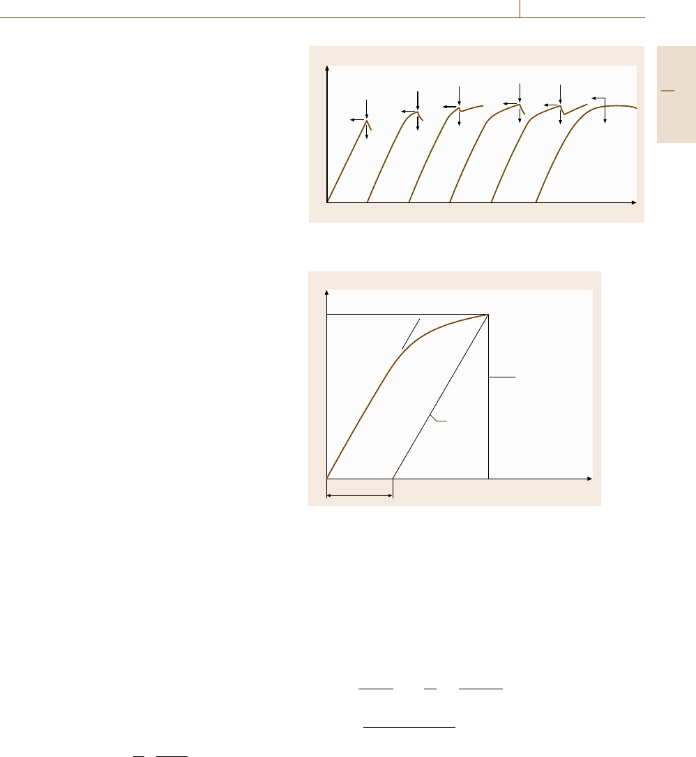
versus notch opening displacement is made. Character-
istic types of load versus displacement records in the
test are shown in Fig. 7.88. Note that P
c
is the applied
load at the onset of brittle crack extension or pop-in
when the average stable crack extension (Δa), including
the stretched zone width (SZW), is less than 0.2mm;
P
u
is the applied load at the onset of brittle crack ex-
tension or pop-in when the event is preceded by Δa
of at least 0.2mm; and P
m
is the applied load at the
first attainment of a maximum load plateau for fully
plastic behavior. If the specimen fractures by brittle
crack extension prior to the first attainment of a max-
imum load plateau (type (4)), the fracture surface is
examined for evidence of stable crack extension in
the region between the fatigue precrack front and the
start of brittle crack extension. When an initiated brittle
crack is arrested after a short extension, the load ver-
sus notch opening record exhibits pop-in, see types (3)
and (5) in Fig. 7.88. Pop-ins giving both a load drop,
y, and displacement increase, x, of less than 1% are
ignored.
The types and the amount of Δa are recorded. The
critical values of the load and notch opening displace-
ment of F
c
and V
c
,orF
u
and V
u
, are measured at points
corresponding to
1. Fracture, when there are no significant pop-ins:
record types (1), (2) and (4);
2. The earliest significant pop-in prior to fracture:
record types (3) and (5);
3. Fracture, when all significant pop-ins prior to frac-
ture give values of d%F that are less than 5%, where
d%F =100
1 −
D
F
F −y
D +x
% . (7.113)
Val ue s o f P
m
and V
m
are measured at points corre-
sponding to
Load P
Notch opening displacement V
P
c
V
c
V
c
V
c
V
u
V
u
V
m
P
c
P
c
P
u
P
u
P
m
(1) (2) (3) (4) (5) (6)
Fracture
Fracture
Fracture
Fracture
Fracture
Fig. 7.88 Characteristic types of load–displacement records in
a CTOD testing (after [7.238])
Load P
0
V
p
V
c
, V
u
or V
m
P
c
, P
u
or P
m
V
Parallel
to 0A
A
Fig. 7.89 Definition of V
p
for determining the CTOD (af-
ter [7.238])
•
First attainment of the maximum load plateau, when
there is no fracture or pop-ins prior to the first attain-
ment of the maximum load plateau: record type (6).
Critical CTOD values, δ
c
, δ
u
, δ
m
, corresponding to
P
c
and V
c
, P
u
and V
u
,orP
m
and V
m
, respectively, are
calculated by
δ =
PS
BW
1.5
× f
a
o
W
2
1 −ν
2
2σ
ys
E
+
0.4
W −a
o
V
p
0.4W +0.6a
o
+z
, (7.114)
where, P is the critical value of the applied load, S is
the bending span, B and W are the thickness and width
of the specimen, respectively (Fig. 7.77), a
o
is average
original crack length, f is a mathematical function of
a
o
/W (7.86)[7.238], σ
ys
is 0.2% of the proof strength at
Part C 7.5