Czichos H., Saito T., Smith L.E. (Eds.) Handbook of Metrology and Testing
Подождите немного. Документ загружается.


378 Part C Materials Properties Measurement
•
The reproducibility of a hardness machine can be
thought of as how well the hardness values agree un-
der changing testing conditions. Influences such as
different machine operators and changes in the test
environment often affect the performance of a hard-
ness machine.
•
The finite resolution of devices that display the hard-
ness value or that measure the size of indentations
prevents the determination of an absolutely accurate
hardness value. Devices such as a dial display on
a Rockwell hardness machine or a portable hand-
scope for measuring Brinell hardness indents may
have a low resolution which can contribute a signif-
icant level of uncertainty to the hardness value.
•
When reported measurement values are based on the
average of multiple hardness tests, the nonunifor-
mity of the material under test contributes a com-
ponent of uncertainty in the hardness value, such as
would occur in the calibration of a reference block.
•
Reference test blocks provide the link to the hard-
ness standard to which traceability is claimed. All
reference hardness blocks should have a reported
uncertainty in the certified hardness value. This
uncertainty contributes to the measurement uncer-
tainty of hardness machines calibrated or verified
with the reference test blocks.
The general approach of this procedure is to calculate
a combined standard uncertainty u
c
by combining the
contributing components of uncertainty u
1
, u
2
,...,u
n
,
for the applicable sources of error discussed above, such
that
u
c
=
u
2
1
+u
2
2
+···+u
2
n
. (7.26)
The appropriate contributing components of uncer-
tainty to combine for this calculation are dependent
on what the uncertainty value represents. For example,
a combined uncertainty may be calculated for a single
hardness value, an average of multiple hardness values,
a hardness machine’s error determined as part of an in-
direct verification, or the certified value resulting from
a reference block calibration.
Measurement uncertainty is usually expressed and
reported as a combined expanded uncertainty U
c
,which
is calculated by multiplying the combined standard un-
certainty u
c
by a numerical coverage factor k, such that
U
c
=ku
c
. (7.27)
A coverage factor is chosen that depends on how well
the standard uncertainty was estimated (number of mea-
surements), and the level of uncertainty that is desired.
The measurement bias b of the hardness machine is the
difference between the expected hardness measurement
results and the true hardness of a material. When test
systems are not corrected for measurement bias, the bias
then contributes to the overall uncertainty in a measure-
ment. Ideally, measurement biases should be corrected;
however, in practice, this is commonly not done for tra-
ditional types of hardness tests. There are a number of
possible methods for incorporating uncorrected biases
into an uncertainty calculation, each of which has both
advantages and disadvantages. A simple and conserva-
tive method is to combine the bias with the expanded
uncertainty as
U = ku
c
+
|
b
|
, (7.28)
where |b| is the absolute value of the bias.
Discussions of the calculations for each of the un-
certainty components, which uncertainty components
should be combined, and how they should be combined
for all types of hardness measurements are too involved
to be described in detail here. Guidance on this ap-
proach can be found in newly developed recommended
procedures recently added to the international hardness
test method standards of ISO and ASTM for the specific
conventional hardness tests.
Reporting Uncertainty
Ideally, an individual measurement uncertainty should
be determined for each hardness scale and hardness
level of interest since the contributing components of
uncertainty may vary depending on the scale and hard-
ness level. In practice, this may not be practical. In
many cases, a single uncertainty value may be applied
to a range of hardness levels based on the laboratory’s
experience and knowledge of the operation of the hard-
ness machine. Also, because several approaches may be
used to evaluate and express measurement uncertainty,
a brief description of what the reported uncertainty
value represents should be included with the reported
uncertainty value.
7.3.4 Instrumented Indentation Test (IIT)
Principle of the Instrumented Indentation Test
[7.183]
The continuous monitoring of the force and the depth
of indentation can allow the determination of hardness
values equivalent to traditional hardness values. More
significantly, additional properties of the material, such
as its indentation modulus and elasto–plastic hardness,
can also be determined. All these values can be calcu-
Part C 7.3
Mechanical Properties 7.3 Hardness 379
1
3
2
h
p
h
r
hh
max
F
max
F
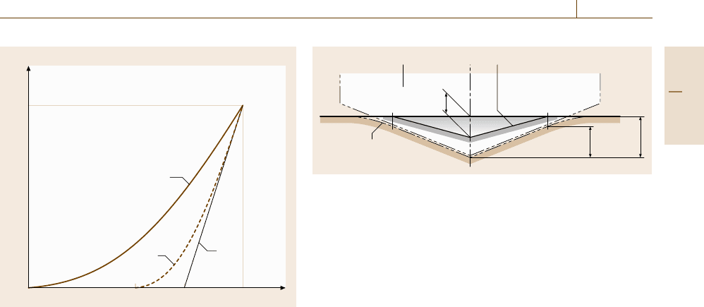
Fig. 7.32 Schematic representation of test procedure (Key:
1 – Application of the test force; 2 – Removal of the test
force; 3 – Tangent to curve 2 at F
max
)
lated without the need to measure the indent optically
(Figs. 7.32, 7.33). An indenter consisting of a material
harder than the material tested with the following shapes
can be used.
1. Diamond indenter shaped as an orthogonal pyra-
mid with a square base and with an angle α =136
◦
between the opposite faces at the vertex (Vickers
pyramid)
2. Diamond pyramid with triangular base (e.g.,
Berkovich pyramid)
3. Hardmetal ball (especially for the determination of
the elastic behavior of materials)
4. Diamond spherical indenter.
For tests at indentation depths of less than 1 μm, the me-
chanical deformation strongly depends on the real shape
of indenter tip and the calculated materials parameters
are significantly influenced by the contact area function
of the indenter used in the testing machine. There-
fore careful calibration of both instrument and indenter
shape is required in order to achieve an acceptable
reproducibility of the material parameters determined
with different machines.
At high contact pressures, damage to the indenter is
possible. For this reason in the force range higher than
2 N, hardmetal indenters are often used. For test pieces
with very high hardness and modulus of elasticity the
influence of indenter deformation on test result should
be taken into account.
3
12
h
max
h
c
h
p
Fig. 7.33 Schematic representation of a cross section through in-
dentation (Key: 1 – Indenter; 2 – Surface of residual plastic
indentation in test piece; 3 – Surface of test piece at maximum
indentation depth and test force)
The test procedure can either be force-controlled
or displacement-controlled. The test force F,thecor-
responding indentation depth h and time are recorded
during the whole test procedure. The result of the test
is the data set of the test force and the relevant in-
dentation depth as a function of time (Fig. 7.32). For
a reproducible determination of the force and cor-
responding indentation depth, the zero point for the
force/indentation depth measurement must be assigned
individually for each test.
Where time-dependent effects are being measured
1. using the force-controlled method, the test force is
kept constant over a specified period and the change
of the indentation depth is measured as a function of
the holding time of the test force,
2. using the indentation-depth-controlled method the
indentation depth is kept constant over a specified
period and the change of the test force is measured
as a function of the holding time of the indentation
depth.
For references for the application of the instrumented
indentation test, see [7.184–202].
Table 7.12 gives the symbols and designations used
for the instrumented indentation test.
Table 7.13 gives an overview about the parameters
of the instrumented indentation test and additional in-
fluence factors on the test result.
Martens Hardness (HM)
Determination of Martens Hardness. Martens hard-
ness is measured under an applied test force. Martens
hardness is determined from the values given by the
force/indentation depth curve during the increasing of
the test force, preferably after reaching the specified test
force. Martens hardness includes the plastic and elastic
Part C 7.3

380 Part C Materials Properties Measurement
Table 7.12 Symbols and designations
Symbol Designation Unit
a,b
α Angle, specific to the shape of the pyramidal indenter
◦
r Radius of spherical indenter mm
F Test force N
F
max
Maximum test force N
h Indentation depth under applied test force mm
h
max
Maximum indentation depth at F
max
mm
h
r
Point of intersection of the tangent to curve 2 at F
max
with the indentation depth axis (Fig. 7.32) mm
h
p
Permanent indentation depth after removal of the test force mm
h
c
Depth of the contact of the indenter with the test piece at F
max
mm
A
s
(h) Surface area of the indenter at distance h from the tip mm
2
A
p
(h
c
) Projected area of contact of the indenter at distance h
c
from the tip mm
2
HM Martens hardness N/mm
2
HM
s
Martens hardness, determined from the slope of the increasing force/indentation depth curve N/mm
2
H
IT
Indentation hardness N/mm
2
E
IT
Indentation modulus N/mm
2
C
IT
Indentation creep %
R
IT
Indentation relaxation %
W
total
Total mechanical work of indentation Nm
W
elast
Elastic reverse deformation work of indentation Nm
η
IT
Relation W
elast
/W
total
%
a
To avoid very long numbers multiples or sub-multiples of the units may be used
b
1N/mm
2
=1MPa
deformation, thus this hardness value can be calculated
for all materials.
Martens hardness is defined for both pyramidal in-
denters. It is not defined for the Knoop indenter or for
ball indenters.
Martens hardness is defined as the test force F
divided by A
s
(h) the surface area of the indenter pen-
etrating beyond the zero point of the contact and is
expressed in N/mm
2
.
The relationship between Martens hardness, inden-
tation depth and test force is given in Fig. 7.34.
(a) Vickers indenter (b) Berkovich indenter
HM =
F
A
s
(h)
=
F
26.43h
2
HM=
F
A
s
(h)
=
F
26.44h
2
(7.29)
A
s
(h) =
4 sin
α
2
cos
2
α
2
h
2
A
s
(h) =
3
√
3tanα
cos α
h
2
(7.30)
Designation of the Martens Hardness [7.184]. The
Martens hardness is denoted by the symbol HM.
Example. HM 0.5/20/20 =8700 N/mm
2
HM 0.5 Test force in N
/20 Application time of test force in s
/20 Duration time of test force in s
=8700 N/mm
2
Hardness value
Indentation Hardness (H
IT
)
Determination of the Indentation Hardness. The in-
dentation hardness H
IT
is a measure of the resistance to
permanent deformation or damage.
H
IT
=
F
max
A
p
, (7.31)
where F
max
is the maximum applied force, A
p
is
the projected (cross-sectional) area of contact between
the indenter and the test piece determined from the
force–displacement curve and a knowledge of the area
function of the indenter, see 4.5.2 of ISO 14577-2.
Equation (7.31) defines hardness as the maximum
applied force, divided by the projected (cross-sectional)
contact area of the indenter with the test piece. This def-
Part C 7.3
Mechanical Properties 7.3 Hardness 381
Table 7.13 Parameters of the instrumented indentation test and additional influence factors on the test result
Martens hardness HM
Martens hardness HM
s
Indentation hardness H
IT
Indentation modul. E
IT
Indentation creep C
IT
Indentation relax. R
IT
Indentation work η
IT
Applied test force × × × × × ×
Applied indentation depth ×
Duration of test force × × × × × ×
Application time of test force ×
Holding time at constant test force × × ×
Holding time at constant indentation depth ×
Time of removal of test force in the curve-fitting range × ×
Material and shape of the indenter
Mode of control (test force or indentation depth)
Approach speed of the indenter
Speed of application of the test force
Speed of application of the indentation depth
Position and duration of additional holding periods
Temperature
× Expressed with the test result
Additional factors that influences the test result
inition is in accord with that generally agreed and first
proposed by Meyer [7.185].
For indentation depths < 6 μm the area function of
the indenter cannot be assumed to be that of the theoret-
ical shape, since all pointed indenters will have some
degree of rounding at the tip and spherically ended
indenters (spherical and conical) are unlikely to have
a uniform radius. The determination of the exact area
function for a given indenter is required for indentation
depths < 6 μm, but is beneficial for larger indentation
depths (see 4.2.1 and 4.6 of ISO 14577-2).
For indentation depths > 6 μm a first approximation
to the projected area A
p
is given by the theoretical shape
of the indenter.
For a perfect Vickers indenter
A
p
=24.5h
2
c
.
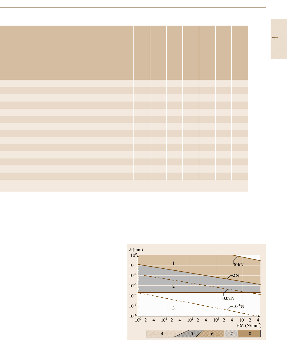
Fig. 7.34 Relationship between Martens hardness, inden-
tation depth and test force (Key: 1 – Macro range; 2 –
Micro range; 3 – Nano range; 4 – Rubber; 5 – Plastics; 6 –
Nonferrous metals; 7 – Steel; 8 – Hardmetals, ceramics)
For a perfect Berkovich indenter
A
p
=23.96h
2
c
.
For a modified Berkovich indenter
A
p
=24.5h
2
c
,
Part C 7.3

382 Part C Materials Properties Measurement
where h
c
is the depth of contact of the indenter with the
test piece calculated as
h
c
= h
max
−ε(h
max
−h
r
) .
Figures 7.32 and 7.33 schematically show the different
depths monitored during an indentation test. The the-
oretical basis of the method for the determination of
contact depth is given in [7.203]. The contact depth is
derived from the force removal curve using the tangent
depth h
r
and the maximum displacement h
max
correct-
ing for elastic displacement of the surface according
to Sneddon’s analysis [7.186], where ε depends on the
indenter geometry (Table 7.14).
h
r
is derived from the force–displacement curve and
is the intercept of the tangent to the unloading cycle at
F
max
with the displacement axis.
Designation of Indentation Hardness H
IT
. The inden-
tation hardness is denoted by the symbol H
IT
.
Example. H
IT
0.5/10/20/30 =11 300 N/mm
2
H
IT
0.5/ Test force in N
10/ Application time of test force in s
20 Duration time of test force in s
/30 Time taken to remove the test force
during the fitted portion of the test
force removal curve in s
=11 300 N/mm
2
Hardness value
Indentation Modulus (E
IT
)
Determination of Indentation Modulus. The indenta-
tion modulus E
IT
can be calculated from the slope of
the tangent for the calculation of indentation hardness
H
IT
and is comparable with the Young’s modulus of the
material
E
IT
=
1 −(ν
s
)
2
1
E
r
−
1−(ν
i
)
2
E
i
, (7.32)
E
r
=
1
β
√
π
2
1
A
p
1
C
s
, (7.33)
Table 7.14 Correction factor ε for different indenter ge-
ometries
Indenter geometry ε
Flat punch 1
Conical 2(π −2)/π =0.73
Paraboloid of revolution
(includes spherical)
3/4
Berkovich, Vickers 3/4
where
ν
s
is the Poisson’s ratio of the test piece;
ν
i
is the Poisson’s ratio of the indenter (for diamond
0.07) [7.187];
E
r
is the reduced modulus of the indentation contact;
E
i
is the modulus of the indenter (for diamond 1.14 ×
10
6
N/mm
2
)[7.187];
C
s
is the compliance of the contact, i. e. dh/dF of the
(frame stiffness corrected) test force removal curve
evaluated at the maximum test force;
β is the correction factor for different tip geometry
(Table 7.15).
Designation of Indentation Modulus. The indentation
modulus is denoted by the symbol E
IT
.
Example. E
IT
0.5/10/20/30 =222 000 N/mm
2
E
IT
0.5/ Test force in N
10/ Application time of test force in s
20 Duration time of test force in s
/30 Time taken to remove the test force
during the fitted portion of the test
force removal curve in s
=222 000 N/mm
2
Indentation modulus
Nanoindentation Method
The elastic and plastic properties of a coating are crit-
ical factors determining the performance of the coated
product. Indeed many coatings are specifically devel-
oped to provide wear resistance that is usually conferred
by their high hardness. Measurement of coating hard-
ness is often used as a quality-control tool. Young’s
modulus becomes important when calculation of the
stress in a coating is required in the design of coated
components. For example, the extent to which coated
components can withstand external applied forces is an
important property in the capability of any coated sys-
tem.
It is relatively straightforward to determine the hard-
ness and indentation modulus of bulk materials using
instrumented indentation. However, when measure-
ments are made normal to a coated surface, depending
Table 7.15 Correction factor β for different indenter ge-
ometries [7.195]
Indenter geometry β
Axis symmetric (e.g. conical, spherical) 1
Berkovich 1.034
Vickers 1.012
Part C 7.3

Mechanical Properties 7.3 Hardness 383
on the force applied and the thickness of the coating, the
substrate properties influence the result.
The purpose of this part of handbook is to provide
guidelines for conditions where there is no significant
influence of the substrate and, where such influence
is detected, to provide possible analytical methods to
enable the coating properties to be extracted from the
composite measurement.
The analysis used here does not make any al-
lowances for pile-up of indents. Use of atomic force
microscopy (AFM) to assess the indent shape allows the
determination of possible pile-up of the surface around
the indent. This surface effect results in an underesti-
mate of the contact area in the analysis and hence may
influence the measured results. Pile-up generally occurs
for fully workhardened materials. Pile-up of soft, duc-
tile materials is more likely for thinner coatings due to
the constraint of the stresses in the zone of plastic de-
formation in the coating. It has been reported that the
piled-up material results in an effective increase of the
contact area for the determination of hardness, while the
effect is less pronounced for the determination of inden-
tation modulus, since the piled-up material behaves less
rigidly [7.197].
Verification and Calibration of Testing Machines. The
instrument shall be calibrated according to the proce-
dures set out in ISO 14577-2 [7.204].
Indirect verification using a reference material shall
be made to ensure the direct calibration is valid and that
no damage or contamination has occurred to the inden-
ter tip. If the results of these initial indentations indicate
the presence of contamination or damage then the inden-
ter should be cleaned using the procedure recommended
in ISO 14577-1 before further trial indents are made. If
indentation into the reference material still indicates the
presence of contamination or damage after cleaning, in-
spection with an optical microscope at a magnification
of 400× is recommended. Detection of submicroscopic
damage or contamination is possible using appropriate
microscopy of indents or the indenter. Where damage is
detected the indenter shall be replaced.
The machine compliance C
f
and the area function
A
p
(h
c
) calibration/verification shall be implemented be-
fore a new indenter is used, see subclause Procedures
for determination of machine compliance and indenter
area function.
The instrumented indentation instrument shall
achieve the required mechanical and thermal stability
before starting an indentation cycle, see subclause Mea-
surement procedure.
Indentation experiments may be performed with
a variety of differently shaped indenters, which should
be chosen to optimize the plastic and elastic defor-
mation required for a given coating substrate system.
Typical indenter shapes are Vickers, Berkovich, coni-
cal, spherical and corner cube. For the determination
of coating plastic properties, pointed indenters are
recommended. The thinner the coating, the sharper
the indenter should be. For the determination of
coating elastic properties, spherical indenters are rec-
ommended. Ideally, a large-radius sphere is used, which
enables indentation in the fully elastic regime over a rea-
sonable indentation displacement. If the radius is too
large, the surface effects (roughness, surface layers etc.)
will dominate the uncertainties. And if the radius is too
small, the maximum force or displacement before plas-
tic deformation begins will be very low. The optimum
radius can be identified by preliminary experiments or
modeling.
Test Piece. Generally surface preparation of the test
piece should be kept to a minimum, and if possible,
the test piece should be used in the as-received state if
surface flatness is consistent with the criteria given in
ISO 14577-1.
The test piece shall be mounted using the same
methods as employed for determination/verification of
the instrument frame compliance, and shall be such that
the test surface is normal to the axis of the indenter and
such that the local surface at the proposed indentation
site is less than ±5
◦
from perpendicular to the inden-
tation axis. Perpendicularity can be checked in practice
by imaging the indent made by a nonaxisymmetric in-
denter.
Indentation into rough surfaces will lead to an in-
creased scatter in the results with decreasing indentation
depth. Clearly when the roughness value R
a
approaches
the same value as the indentation depth the contact area
will vary greatly from indent to indent, depending on
its position relative to peaks and valleys at the surface.
Thus it is recommended that the final surface finish
shall be as smooth as available experience and facili-
ties permit. The R
a
value should be less than 5% of the
maximum penetration depth whenever possible.
It has been shown that, for a Berkovich indenter,
the angle that the surface normal presents to the axis
of indentation has to be greater than 7
◦
for significant
errors to result [7.198]. The important angle is that be-
tween the indentation axis and the local surface normal
at the point of contact. This angle may be significantly
different to the average surface plane for rough surfaces.
Part C 7.3

384 Part C Materials Properties Measurement
While R
a
has been recommended as a practical
and easily understood roughness parameter, it should
be borne in mind that this is an average, and thus
single peaks and valleys may be greater than this, as
defined by the R
z
value, although the likelihood of
encountering the maximum peak, for example, on the
surface is small. Modeling to investigate the roughness
of the coating surface has concluded that there are two
limiting situations for any R
a
value. When the wave-
length of the roughness (in the plane of the coating
surface) is much greater than the indenter tip radius,
the force–penetration response is determined by the lo-
cal coating-surface curvature, but when the wavelength
is much less than the tip radius, asperity contact oc-
curs and the effect is similar to having an additional
lower-modulus coating on the surface.
In cases where coatings are used in the as-received
condition, nevertheless, random defects occur such as
nodular growths or scratches and where an optical
system is included in the testing machine, it is rec-
ommended that flat areas away from these defects are
selected for measurement.
The roughness profilometer probe radius should be
comparable to the indenter radius. If the roughness pa-
rameter R
a
is determined with an AFM on a scan area,
the size of this area should be agreed upon between the
customer and the measurement laboratory. A scan area
of 10 μmby10μm is recommended.
It should be appreciated that mechanical polishing
of surfaces may result in a change in the workhardening
and/or the residual stress state of the surface and conse-
quently the measured hardness. For ceramics this is less
of a concern than for metals, although surface damage
may occur. Grinding and polishing shall be carried out
such that any stress induced by the previous stage is re-
moved by the subsequent stage and the final stage shall
be with a grade of polishing medium appropriate to the
displacement scale being used in the test.
Many coatings replicate the surface finish of the
substrate. If it is acceptable to do so, surface-preparation
problems can be reduced by ensuring that the substrate
has an appropriate surface finish, thus eliminating the
need to prepare the surface of the coating. In some
cases, however, changing the substrate surface rough-
ness may affect other coating properties; therefore, care
should be taken when using this approach.
In coatings it is common for there to be relatively
large residual stresses e.g. arising from thermal expan-
sion coefficient mismatch between the coating and the
substrate and/or stress induced by the coating deposition
process. Thus, a stress-free surface would not normally
be expected. Furthermore, stress gradients in coatings
are not uncommon, so that removal of excessive ma-
terial during a remedial surface preparation stage may
result in a significant departure from the original surface
state.
Polishing reduces the coating thickness and so the
effects of the substrate will be enhanced. Where the data
analysis requires an accurate knowledge of the coating
thickness indented, polishing will require remeasure-
ment of the coating thickness. This again emphasizes
the need to carry out minimum preparation.
Generally, provided the surface is free from obvious
surface contamination, cleaning procedures should be
avoided. If cleaning is required, it shall be limited to
methods that minimize damage, e.g.
•
application of a dry oil-free filtered gas stream
•
application of subliming particle stream of CO
2
(avoiding surface temperatures below the dew point)
•
application of ultrasonic methods
•
rinse with a solvent (which is chemically inert to the
test piece) and then dry.
If these methods fail and the surface is sufficiently ro-
bust, the surface may be wiped with a lintless tissue
soaked in solvent to remove trapped dust particles and
the surface shall be rinsed in a solvent as above. Ultra-
sonic methods may not be used as these are known to
create or increase damage to coatings.
Test Conditions. Indenter geometry, maximum force
and/or displacement and force displacement cycle (with
suitable hold periods) shall be selected by the operator
to be appropriate to the coating to be measured and the
operating parameters of the instrument used.
It is important that the test results are not affected by
the presence of an interface, free surface or by any plas-
tic deformation introduced by a previous indentation in
a series. The effect of any of these depends on the in-
denter geometry and the materials properties of the test
piece. Indentations shall be at least three times their in-
dentation diameter away from interfaces or free surfaces
and, where multiple indentations are planned, the mini-
mum distance between indentations shall be at least five
times the largest indentation diameter.
The indentation diameter is the in-plane diameter at
the surface of the test piece of the circular impression of
an indent created by a spherical indenter. For noncircu-
lar impressions, the indentation diameter is the diameter
of the smallest circle capable of enclosing the inden-
tation. Occasional cracking may occur at the corners
Part C 7.3
Mechanical Properties 7.3 Hardness 385
of the indentation. When this occurs, the indentation
diameter should enclose the crack.
The minimum distances specified are best applica-
ble to ceramic materials and metals such as iron and its
alloys. For other materials it is recommended that sepa-
rations of at least ten indentation diameters be used. If in
doubt, it is recommended that the values from the first
indentation are compared with those from subsequent
indentations in a series. If there is a significant differ-
ence, the indentations may be too close and the distance
should be increased. A twofold increase is suggested.
The following parameters of coating/substrate influ-
encing the measurement result should be considered.
1. Substrate hardness, Young’s modulus and Poisson’s
ratio
2. Coating thickness
3. Surface roughness
4. Adhesion of the coating to the substrate.
All these parameters should be kept constant if a di-
rect comparison is to be made between two or more test
pieces.
The time dependence of the materials parameter
should be taken into account.
Variations in test-piece parameters other than hard-
ness or modulus can affect measurement of these
quantities. If the indentation depth is a sufficiently
small fraction of the coating thickness, or the coating
Use hold to
estimate drift
Hold at contact
Elastic limit
exceeded
Take into account:
Surface layers,
vibration
Linear correction of
displacement
Take into account:
Creep,
viscoelasticity,
cracking,
surface layers,
vibration
Drift removed using
reference surface
before and after
Significant
Possible
Not possible
Yes
No
Noise is
high
Not
significant
Don't need to
correct
Hold at 90% unload
Take into account:
Creep (recovery),
viscoelasticity,
cracking (tensile),
stiff contacts
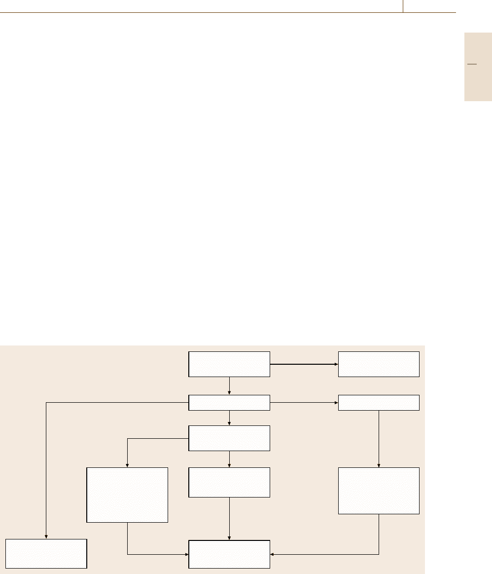
Fig. 7.35 Decision tree to assist in estimating the drift during a force-controlled experiment
thickness is well known, it is possible to compare coat-
ings of different thickness. The exact limits depend on
the ratio of properties of coating and substrate. It is
recommended that methods for normalizing results to
determine coating properties from coatings of different
thickness always be used.
Measurement Procedure. Introduce the prepared test
piece and position it so that testing can be undertaken
at the desired location. Carry out the predetermined
number of indentation cycles using the selected test
conditions.
A single force application and removal cycle shall
be used. A decision tree to assist in estimating the ther-
mal drift during the experiment is shown in Fig. 7.35.If
the drift rate is significant the displacement data shall be
corrected by measuring the drift rate during a hold at as
close to zero force as is practicable or at 90% removed
force. The hold period shall be sufficient to allow deter-
mination of the drift in displacement due to temperature
fluctuations. Drift (as opposed to noise) in displacement
values determined during the hold period at 90% force
removal or at close to zero is believed to result from
temperature changes, and, a linear correction should be
applied such that
(corrected displacement)
=(displacement) −(thermal drift rate) × time .
Part C 7.3

386 Part C Materials Properties Measurement
If a contact in the fully elastic regime can be obtained,
a hold at initial contact is preferred. In this way, ma-
terial influences (creep, viscoelasticity, cracking) can
be avoided. If no elastic contact can be obtained, de-
pending on the material under investigation, a hold at
initial force (e.g. viscoelastic material) or at 90% re-
moved force (e.g. soft material) may be preferred. For
difficult materials, a hold period at both ends of the in-
dentation cycle may be included. It is recommended that
the first 10–20 s of the hold data should be discarded
for the analysis since these initial data may be signif-
icantly influenced by time-dependent effects (material
time-dependent deformation, formation of capillary sur-
face layers) [7.199,200].
A further hold period shall be performed at maxi-
mum force to allow for completion of any time-depen-
dent deformation. In all cases this hold period shall be
long enough to reduce the error in the slope of the force
removal curve to less than 1%. The minimum hold-
period length is therefore dependent on the instrument
capability and the material being tested. The hold period
shall be long enough and/or the time to remove force
shall be short enough such that
(creep rate)× (time to remove force)
< F
max
/S/100 .
Force application and removal rates may be the same
but it is recommended that the removal rate should be
higher than the application rate (if possible) to minimize
the influence of creep. Slower force application reduces
the hold period length required at F
max
to achieve the
necessary reduction in creep rate.
The influence of the material creep behavior on
hardness and modulus results has been reported [7.199].
The results show that, especially for materials with low
hardness-to-modulus ratio (among them most metals),
the modulus results are not reliable if the hold period
is too short. A modulus error, due to creep, of more
than 50% may arise. The variation of the hold period
produced a hardness change of up to 18%. Reference
[7.199] proposes hold periods dependent on the mater-
ial type that range from 8 s for fused quartz to 187 s for
aluminum. The criterion used was that the creep rate
should have decayed to a value where the depth increase
in one minute is less than 1% of the indentation depth.
It is recommended that the creep rate be assessed in
preliminary experiments.
Data Analysis and Evaluation of Results. The hardness
and indentation modulus of the test piece can be calcu-
lated using (7.31)–(7.33). The properties thus calculated
are composite properties for the coating/substrate com-
bination. This clause provide methods for extracting the
indentation modulus of the coating from the composite
properties measured, assuming that the coating proper-
ties are constant with depth.
For hardness measurement of electroplated coatings
on steels [7.201], it is recommended that the indenta-
tion depth does not exceed one tenth the thickness of
the coating, while for paint films [7.202] penetration of
up to one third the coating thickness may be allowed.
These approximations can be unsatisfactory in many
cases. Test parameters for ductile and brittle coatings
need to be considered separately.
For in-plane indentation, elastic deformation of the
substrate will mostly occur for all coatings, even though
this could be negligibly small for a thick compliant coat-
ing on a stiff substrate. Thus the measured modulus will
be the composite modulus of the coating and substrate
and the value obtained will be a function of indentation
depth.
For hardness measurement it is recommended to use
as small a radius indenter (i. e. as sharp) as possible
to limit the plastic deformation to be within the coat-
ing. A measurement of the uncoated substrate hardness
is a useful guide to the appropriate choice of analysis
(soft versus hard). In some circumstances it is possi-
ble to identify a range of indentation depth over which
the measured hardness is constant (i. e. before the on-
set of substrate plastic deformation) and then carry out
indentation experiments within this range.
Estimates of coating hardness and modulus may
be extracted from the composite values E
IT
, H
IT
ob-
tained from in-plane indentation by expressing those
composite values as a function of the contact radius
a or indentation depth h
c
normalized to the coating
thickness. Measurement of the coating thickness t
c
is
recommended for reproducible measurement of coating
properties. For indenters of different geometries (e.g.,
Berkovich, Vickers, spherical, cone, etc.), a is approxi-
mated by the radius of a circle having the same area as
the projected area of contact with the indenter
a =
A
p
π
. (7.34)
This value has exact equivalence for a spherical or con-
ical indenter but becomes increasingly less physically
meaningful as the axial symmetry of the indenter re-
duces, i. e. cone = sphere > Vickers > Berkovich.
It is relatively easy to measure the hardness of duc-
tile coatings or the elastic modulus of brittle coatings. It
is more difficult to determine the hardness of brittle or
Part C 7.3
Mechanical Properties 7.3 Hardness 387
hard coatings or the elastic modulus of ductile coatings.
Where t
c
is not measured, nominal values of t
c
may
be used but comparison between coatings of different
thicknesses will be less accurate.
In the case of force-controlled cycles and test pieces
of unknown indentation response, a set of trial inden-
tations shall be performed (e.g. at two widely spaced
forces) and analyzed to enable estimates of the test force
required for the range of a/t
c
specified below.
In the case of soft/ductile coatings indentation force
or displacement and indenter geometry shall be chosen
such that data shall be obtained in the region where
a/t
c
< 1.5. The coating indentation modulus E
IT
is
obtained by taking a series of measurements at dif-
ferent indentation depths and extrapolating a linear
fit to indentation elastic modulus versus a/t
c
to zero
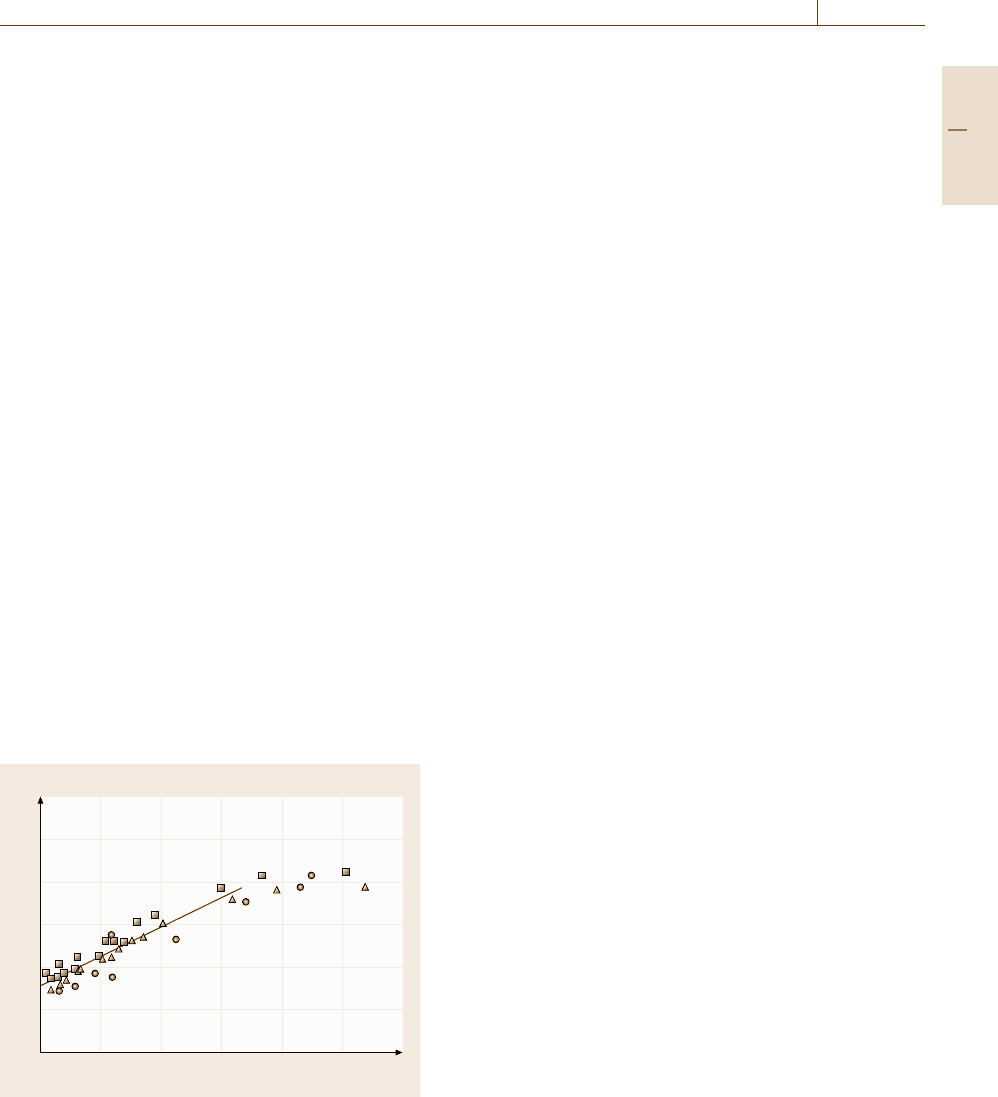
(Fig. 7.36).
A linear fit to indentation elastic modulus ver-
sus a/t
c
to zero is a first approximation in the range
a/t
c
< 2. However, in general, a nonlinear relationship
appears and can be reproduced by finite element anal-
ysis (FEA). The exact nature of this nonlinear relation
is not known and so a linear fit over the restricted range
indicated is a robust first approximation but is not appli-
cable over a range wider than this.
For the determination of coating indentation hard-
ness, it is recommended that an elastic stress analysis
of the coating/substrate system be undertaken using
the approximation of a spherical indenter of a radius
equivalent to the tip radius of the self-similar-geometry
indenter. This will determine whether the coating or the
E
*
IT
(GPa)
300
250
200
150
100
50
0
0 0.5 1 1.5 2 2.5 3
a/t
c
Fig. 7.36 Indentation reduced elastic modulus versus nor-
malized contact radius Au on Ni, selected data for spherical
(filled circle), Berkovich (filled triangle) and Vickers (filled
square) indenter
substrate will yield first during indentation and therefore
whether it is possible to determine the coating hard-
ness at all. It is recommended that hardness values for
the substrate be obtained for comparison, by testing if
necessary. Delamination or fracture of the coating can
be recognized by the hardness values obtained, clus-
tering at the substrate value, even at low h
c
/t
c
.Note
that sharper indenters may cause fracture at lower forces
than blunter indenters.
In the case of hard coatings on a softer substrate,
the indentation force or displacement and indenter ge-
ometry shall be chosen such that h
c
/t
c
(or ≈ a/t
c
)is
in a range where H
IT
is a maximum. Commonly, the
range is 0 < h
c
/t
c
< 0.5. If a constant maximum value
of H
IT
(a plateau) is observed over this range, this
is the coating indentation hardness. If only a maxi-
mum in H
IT
occurs and indentation of a thicker coating
yields the same value, then this is a strong indicator
that this is the value for the coating. Otherwise this is
only the minimum estimate of the coating indentation
hardness.
The extent of substrate plastic deformation will de-
pend upon a number of factors, including the relative
difference in hardness and modulus between the coating
and the substrate, adhesion, the coating thickness, the
indenter radius of curvature (sharpness) and the maxi-
mum force.
To measure the coating hardness the coating must
yield sufficiently before the substrate yields. The best
conditions for this are when the maximum of the von
Mises stress is inside the thickness of the coating and
causes plastic deformation whilst the stress in the sub-
strate below does not exceed the substrate yield stress.
In a spherical contact, the maximum of the von Mises
stress is approximately 0.47× (mean pressure) at 0.5a
below the surface.
Procedures for Determination of Machine Compli-
ance and Indenter Area Function. The calibration
procedures detailed below require the use of refer-
ence materials (see ISO 14577-3 [7.205]) which shall
be isotropic and homogeneous. The Young’s modulus
and Poisson’s ratio are assumed to be independent of
the indentation depth. Some procedures need reference
materials of known Young’s modulus and Poisson’s
ratio.
Currently recommended materials are freshly pol-
ished tungsten and fused silica. The forces used should
not exceed the threshold at which cracking occurs
(≈80–100 mN for an average radius Berkovich tip in-
denting fused silica).
Part C 7.3