Dinc Ibrahim. Refrigeration systems and applications 2th edition
Подождите немного. Документ загружается.

Refrigeration Cycles and Systems 171
Air in a refrigeration system robs it of its capacity to function, and failure to remove such air
can be costly in terms of operating efficiency and equipment damage. Such damage is especially
notable in the industrial-sized refrigeration systems commonly used in major cold storage facilities,
food processing plants, and some chemical plants.
Regardless of whether a system is charged with ammonia or a Freon refrigerant, the thermal
efficiency of such systems will greatly improve when undesirable, noncondensable gas (air) is
removed. The process of removing air, which is colorless and odorless, is called purging. Over
time, this process has become increasingly automatic. But, it is important to understand why,
where, and how to purge the system before attempting to rely on an automatic purging system.
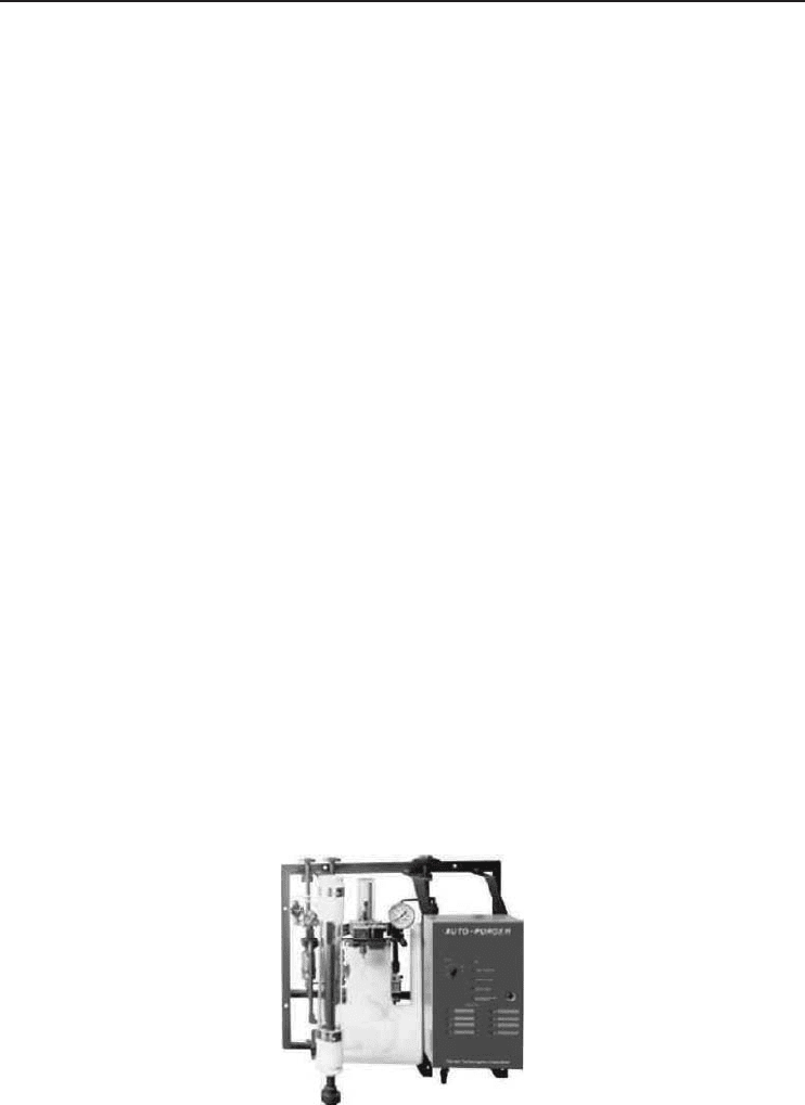
Figure 4.9 shows an industrial air purger unit.
Air can enter a refrigeration system through several places (Rockwell and Quake, 2001):
• When suction pressure is below atmospheric conditions, air can enter through seals and valve
packing.
• Air can rush in when the system is open for repair, coil cleaning, or adding equipment.
• Air can enter when the refrigerant truck is charging the system or when oil is being added.
Therefore, the accumulated air has negative impact on the system performance, which can be
summarized as follows:
• Accumulated air insulates the transfer surface and effectively reduces the size of the condenser.
To offset this size reduction, the system must work harder by increasing the pressure and
temperature of the refrigerant. Therefore, removal of air, as quickly and as efficiently as
possible, is essential.
• Air in the system can result in excess wear and tear on bearings and drive motors and contribute
to a shorter service life for seals and belts. Also, the added head pressure increases the likelihood
of premature gasket failures. It can also decrease the power cost to operate the compressor by
about 2% for each 1% reduction in compressor capacity. Thus, it is essential to choose the proper
size and type of purger for the job.
The easiest way to determine the amount of air in a refrigeration system is to check the condenser
pressure and the temperature of the refrigerant leaving the condenser. Then, these findings should
be compared with the standard temperature–pressure for that particular refrigerant.
Figure 4.9 An industrial air purger (Courtesy of Hansen Technologies Corporation).
172 Refrigeration Systems and Applications
Example 4.3
If, for example, the ammonia temperature is 30
◦
C, the theoretical condenser pressure should be
1065.2 kPa. If your gauge reads 1199.7 kPa, the excess pressure is 134.5 kPa. Under this condition,
the power costs increase by 10% and the compressor capacity decreases by 5%, as determined by the
per kWh cost of energy. As an example, if the pressure is reduced by 20 psi (138 kPa) and the
cost of electricity is $0.05 per kWh, the annual savings will be more than $2600 per 100 tons (for
details, see Rockwell and Quake, 2001).
4.5.3.1 Air Purging Methods
Basically, there are two ways to purge a system of air: manual or automatic. To purge manually, a
properly positioned valve is opened by hand, allowing the air to escape. It is a common miscon-
ception that when a cloud of refrigerant gas is seen being discharged to atmosphere, the system
has been purged of air. Air can still be trapped in the system.
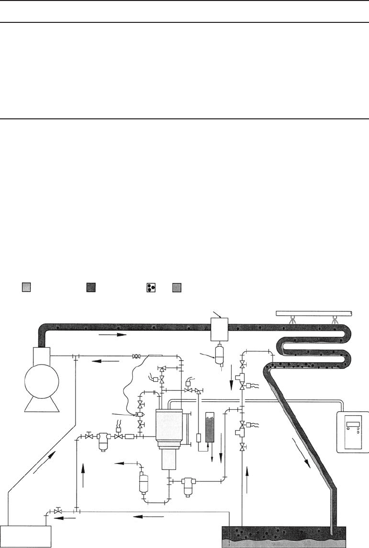
Therefore, many refrigeration system users prefer automatic purging. Refrigeration systems
include the compressor, condenser, receiver, evaporator, and purger (Figure 4.10). Of these com-
ponents, the purger is perhaps the least understood and appreciated. The purger’s job is to remove
air from the system, thus improving compressor and condenser operating efficiency.
Two types of automatic purgers are used as follows (Rockwell and Quake, 2001): (i) nonelectrical
mechanical and (ii) automatic electronic purgers. Determining the type of automatic purger to use
Key: Liquid refrigerant Refrigerant gas Air Water
Oil separator
Armstrong
oil drain trap
Condenser
Electronic
purger
controller
Armstrong
strainer
Evaporator
Armstrong
liquid
seal
Note: A, B and C = Solenoid valves included
D and E = Metering valves included
Armstrong
strainer
Receiver
A
B
D
C
E
K-3
MP
purger
Bubbler
(optional)
Purge point
valve
(optional)
Expansion
valve
Compressor
Figure 4.10 A basic refrigeration system with multipoint purger (Courtesy of Armstrong International, Inc.).

Refrigeration Cycles and Systems 173
is a matter of whether electricity is available at the purger location and if it safe to allow electrical
components to be used. The nonelectrical mechanical units are used primarily in applications where
electricity is not available at the point of use or in hazardous applications where electric components
are not allowed. They remove air by sensing the density difference between the liquid refrigerant
and gases. An operator opens and closes valves to start and stop the purging operation and ensure
its efficiency. Electronic automatic refrigeration purgers are classed as single-point and multipoint
purgers. The single-point electronic refrigerated purger has a mechanical-purge operation with a
temperature/gas level monitor that controls the discharge to atmosphere. The purging sequence
is performed manually. A multipoint refrigerated purger will purge a number of points using the
same unit. However, each purge point is purged individually, and the multipoint purger offers total
automation, including start-up, shutdown, and alarm features. With this purger, it is important to
choose a purger designed for the total tonnage of your system. Undersized purgers may cost less
initially but may adversely impact the system’s efficiencies and payback period. Some multipoint
purgers include a microprocessor-based programmable controller rather than a clock timer. The
fuzzy logic controller can “learn” as it cycles through the system. As the purger accumulates air
and purges, the controller records and prioritizes each purge point in its memory, thus removing
air more efficiently.
Example 4.4
A practical refrigerator operates on the vapor-compression refrigeration cycle with refrigerant-22
as the working fluid. The pressure of R-22 is 300 psia at the compressor exit, and 50 psia at the
evaporator inlet. The isentropic efficiency of the compressor is 80%. The refrigerant is superheated
by 10
◦
F at the compressor inlet and subcooled by 10
◦
F at the exit of the condenser. There is a
pressure drop of 10 psia in the condenser and 5 psia in the evaporator. Determine (a) the heat
absorption in the evaporator per unit mass of R-22, the work input, and the COP. (b) Determine the
refrigeration load, the work input, and the COP if the cycle operated on the ideal vapor-compression
refrigeration cycle between the pressure limits of 300 and 50 psia.
The properties of R-22 in the case of actual operation are obtained from R-22 tables to be
h
1
= 173.44 Btu/Ibm, h
2
= 200.37 Btu/Ibm, h
3
= 110.65 Btu/Ibm, h
4
= 110.65 Btu/Ibm
The properties of R-22 in the case of ideal operation are obtained from R-22 tables to be
h
1
= 172.30 Btu/Ibm, h
2
= 191.99 Btu/Ibm, h
3
= 114.90 Btu/Ibm, h
4
= 114.90 Btu/Ibm
Solution
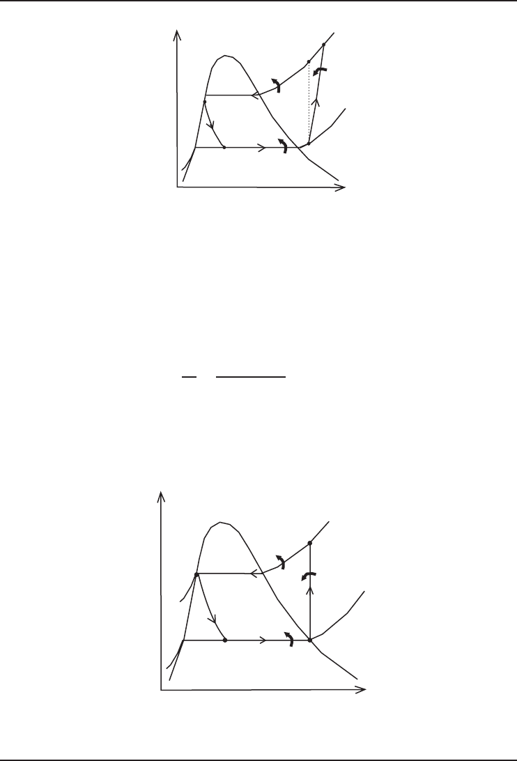
(a) Temperature–entropy diagram of the cycle for the actual operating conditions is given in
Figure 4.11.
The heat absorption in the evaporator per unit mass of R-22, the work input, and the COP are
determined as follows:
q
L
= h
1
− h
4
= 173.44 − 110.65 = 62.8Btu/lbm
q
H
= h
2
− h
3
= 200.37 − 110.65 = 89.7Btu/lbm
w = h
2
− h
1
= 200.37 − 173.44 = 26.9Btu/lbm
COP =
q
L
w
=
62.8 Btu/lbm
26.9 Btu/lbm
= 2.33
174 Refrigeration Systems and Applications
q
H
q
L
1
2s
3
4
s
T
2
w
Figure 4.11 Temperature–entropy diagram of vapor-compression refrigeration cycle considered in the solution
of Example 4.4a.
(b) Temperature–entropy diagram of the ideal cycle is given in Figure 4.12.
Ideal vapor-compression refrigeration cycle solution is as follows:
q
L
= h
1
− h
4
= 172.30 − 114.90 = 57.4Btu/lbm
q
H
= h
2
− h
3
= 191.99 − 114.90 = 77.1Btu/lbm
w = h
2
− h
1
= 191.99 − 172.30 = 19.7Btu/lbm
COP =
q
L
w
=
57.4 Btu/lbm
19.7 Btu/lbm
= 2.91
In the ideal operation, the refrigeration load decreases by 8.6% and the work input by
26.8% while the COP increases by 24.9%. Also, it can be shown that the cycle operation in
part (a) with a compressor isentropic efficiency of 100% would give the following results:
q
L
= 62.8 Btu/lbm, q
H
= 84.3 Btu/lbm, w = 21.6 Btu/lbm, COP = 2.91.
q
H
q
L
50 psia
1
2
3
4
300 psia
s
T
w
Figure 4.12 Temperature–entropy diagram of the ideal vapor-compression refrigeration cycle considered in
Example 4.4b.
Refrigeration Cycles and Systems 175
4.5.4 Twin Refrigeration System
The twin refrigeration system is a new refrigeration technology that solves the problems of
conventional vapor-compression refrigerators. A no-frost cooling system is the latest craze, but
conventional no-frost features reduce energy efficiency and humidity. To overcome this problem, a
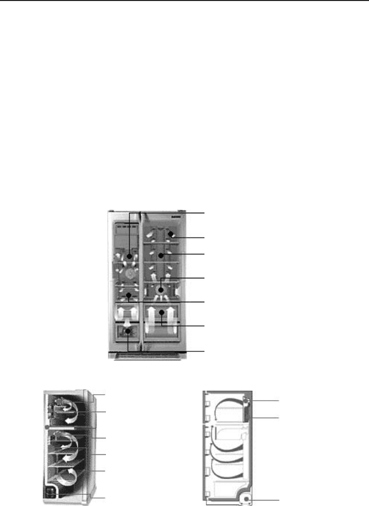
new refrigeration system, named the Twin Refrigeration System (Figure 4.13a) has been developed
by Samsung. Here are the primary features of this new system:
• Two evaporators and two fans. The evaporators and fans of the freezer and the refrigerator
operate independently to achieve the necessary temperature in each compartment. This minimizes
unnecessary airflow from one compartment to another. It eliminates the need for a complicated
air flow system which would lead to energy loss.
• Turbo fans. Newly developed turbo-fan and multiple-scroll air distribution duct system mini-
mizes the air path.
• Inverting compressor. Variable compressor PRM according to the condition of the refrigerator
4-step control is utilized.
Turbo fan for
the freezer
Fan for freezer
Cooling fan
Evaporator
shared by
freezer and
fridge
Compresso
r
Fan for fridge
Turbo fan for
the refrigerator
Evaporator for
the freezer
Evaporator for
freezer
Evaporator for
fridge
Compressor
No air circulation
Evaporator for
the refrigerator
High efficiency
compressor
(a)
Multiflow
Temperature
sensor
(b) (c)
Figure 4.13 (a) A twin refrigeration system and its components. Comparison of (b) a twin refrigeration system
with (c) a conventional no-frost system (Courtesy of Samsung Electronics).

176 Refrigeration Systems and Applications
• High-efficiency fan motors. Brushless DC variable motors are employed.
• High-efficiency insulation. The insulation material is cyclo-pentane. It helps minimize heat
penetration, because of its low thermal conductivity.
• CFC-free. All these new refrigerators use R-134a and R-600a only, and are free of CFC and
HCFC. Therefore, they are environmentally benign.
As seen in Figure 4.13a, the system has both freezer and refrigerator compartments which are
controlled independently because of each compartment’s separate evaporator and precise control
unit. These features also eliminate inefficient air circulation between the compartments. The result
is considered a technological ingenuity, because of the following:
• high humidity preservation,
• ideal constant temperature storage,
• high energy savings, and
• no mixed odors between compartments.
4.6 Air-Standard Refrigeration Systems
The air-standard refrigeration cycles are also known as the reverse Brayton cycles. In these sys-
tems, refrigeration is accomplished by means of a noncondensing gas (e.g., air) cycle rather than
a refrigerant vapor cycle. While the refrigeration load per kilogram of refrigerant circulated in a
vapor-compression cycle is equal to a large fraction of the enthalpy of vaporization, in an air cycle
it is only the product of the temperature rise of the gas in the low-side heat exchanger and the
specific heat of the gas. Therefore, a large refrigeration load requires a large mass rate of circula-
tion. In order to keep the equipment size smaller, the complete unit may be under pressure, which
requires a closed cycle. The throttling valve used for the expansion process in a vapor-compression
refrigeration cycle is usually replaced by an expansion engine (e.g., expander) for an air cycle
refrigeration system. The work required for the refrigeration effect is provided by the gas refriger-
ant. These systems are of great interest in applications where the weight of the refrigerating unit
must be kept to a minimum, for example, in aircraft cabin cooling.
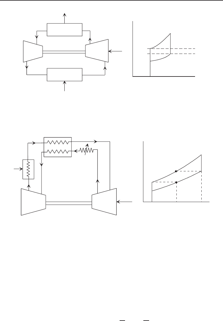
A schematic arrangement of a basic air-standard refrigeration cycle and its T –s diagram is shown
in Figure 4.14. This system has four main elements:
• a compressor that raises the pressure of the refrigerant from its lowest to its highest value
(e.g., isentropic compression: 1–2),
• an energy output heat exchanger where the high temperature of the refrigerant is lowered
(e.g., isobaric heat rejection: 2–3),
• an expander where the pressure and temperature of the refrigerant are reduced (e.g., isentropic
expansion: 3–4), and
• an energy input heat exchanger that raises the temperature of the refrigerant at a constant pressure
(e.g., isobaric heat input: 4−1). This input is known as refrigeration load.
The utilization of air as a refrigerant becomes more attractive when a double purpose is to be
met. This is so in the case of air conditioning, when the air can be both the refrigerating and
the air conditioning medium. Figure 4.15 shows an air-standard refrigeration cycle using a heat
exchanger and its T –s diagram. Furthermore, air-standard refrigeration cycle is commonly used in
the liquefaction of air and other gases and also in certain cases where refrigeration is needed such
as aircraft cooling systems.
Refrigeration Cycles and Systems 177
Heat exchanger I
Heat exchanger II
Compressor
Expander
1
2
3
4
Q
L
Q
H
W
1
2
3
4
T
0
(Surroundings)
T
L
T
s
(a) (b)
·
·
·
Figure 4.14 (a) A basic air-standard refrigeration cycle and (b) its T –s diagram.
Compressor
Expander
Heat exchanger
W
net
Q
L
Q
H
1
2
3
4
5
6
T
sabc
1
2
3
4
5
6
T
0
(a) (b)
Figure 4.15 (a) An air-standard refrigeration cycle using a heat exchanger and (b) its T –s diagram.
4.6.1 Energy and Exergy Analyses of a Basic Air-Standard
Refrigeration Cycle
Here, in energy analysis of a basic air-standard refrigeration cycle as shown in Figure 4.14, we
follow the same methodology that we used in energy analysis of a vapor-compression refrigeration
cycle. The only difference is that we can treat the gaseous working fluid (i.e., air) as an ideal gas.
Therefore, we can write the following for enthalpy and entropy difference equations:
h = (h
e
− h
i
) = c
p
T = c
p
(T
e
− T
i
) (4.28)
s = (s
e
− s
i
) = c
p
ln
T
e
T
i
− R ln
P
e
P
i
(4.29)

178 Refrigeration Systems and Applications
where the subscripts i and e represent inlet and exit states, respectively. On the basis of Figure 4.14,
we list the energy balance equations and exergy destructions for the components of the system as
follows:
• For compressor:
˙mh
1
+
˙
W
Comp
=˙mh
2
⇒
˙
W
Comp
=˙m(h
2
− h
1
) =˙mc
p
(T
2
− T
1
) (4.30)
˙
Ex
dest,1– 2
= T
0
˙
S
gen,1 – 2
=˙mT
0
(s
2
− s
1
) =˙mT
0
c
p
ln
T
2
T
1
− R ln
P
2
P
1
• For heat exchanger II (i.e., condenser):
˙mh
2
=˙mh
3
+
˙
Q
H
⇒
˙
Q
H
=˙m(h
2
− h
3
) =˙mc
p
(T
2
− T
3
) (4.31)
˙
Ex
dest,2– 3
= T
0
˙
S
gen,2– 3
=˙mT
0
s
3
− s
2
+
q
H
T
H
=˙mT
0
c
p
ln
T
3
T
2
− R ln
P
3
P
2
+
q
H
T
H
• For expander (turbine):
˙mh
3
=˙mh
4
+
˙
W
Turb
⇒
˙
W
Turb
=˙m(h
3
− h
4
) =˙mc
p
(T
3
− T
4
) (4.32)
˙
Ex
dest,3– 4
= T
0
˙
S
gen,3– 4
=˙mT
0
(s
4
− s
3
) =˙mT
0
c
p
ln
T
4
T
3
− R ln
P
4
P
3
• For heat exchanger I (i.e., evaporator):
˙mh
4
+
˙
Q
L
=˙mh
1
⇒
˙
Q
L
=˙m(h
1
− h
4
) =˙mc
p
(T
1
− T
4
) (4.33)
˙
Ex
dest,4– 1
= T
0
˙
S
gen,4– 1
=˙mT
0
s
1
− s
4
−
q
L
T
L
=˙mT
0
c
p
ln
T
1
T
4
− R ln
P
1
P
4
−
q
L
T
L
For the entire refrigeration system, the energy balance can be written as
˙
W
Comp
+
˙
Q
L
=
˙
W
Turb
+
˙
Q
H
(4.34)
The net work for the system becomes
˙
W
net
=
˙
W
Comp
−
˙
W
Turb
(4.35)
The COP of the air-standard refrigeration system is
COP =
˙
Q
L
˙
W
net
(4.36)
The total exergy destruction in the cycle can be determined by adding exergy destructions in
each component:
˙
Ex
dest,total
=
˙
Ex
dest,1– 2
+
˙
Ex
dest,2 – 3
+
˙
Ex
dest,3– 4
+
˙
Ex
dest,4– 1
(4.37)
It can also be expressed as
˙
Ex
dest,total
=
˙
W
net
−
˙
Ex
˙
Q
L
(4.38)
where the exergy of the heat transferred from the low-temperature medium is given by
˙
Ex
˙
Q
L
=−
˙
Q
L
1 −
T
0
T
L
(4.39)
Refrigeration Cycles and Systems 179
This is in fact the minimum power input to accomplish the required refrigeration load
˙
Q
L
:
˙
W
min
=
˙
Ex
˙
Q
L
(4.40)
The second-law efficiency (or exergy efficiency) of the cycle is defined as
η
II
=
˙
Ex
˙
Q
L
˙
W
net
=
˙
W
min
˙
W
net
= 1 −
˙
Ex
dest,total
˙
W
net
(4.41)
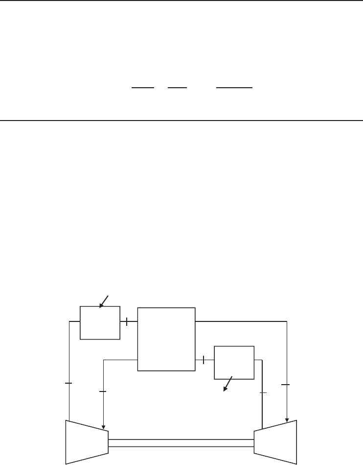
Example 4.5
Air enters the compressor of a gas refrigeration system with a regenerator at −20
◦
Cataflowrate
of 0.45 kg/s (Figure 4.16). The cycle has a pressure ratio of 4. The temperature of the air decreases
from 16 to −30
◦
C in the regenerator. The isentropic efficiency of the compressor is 82% and that
of the turbine is 84%. Determine (a) the rate of refrigeration and the COP of the cycle and (b) the
minimum power input, the second-law efficiency of the cycle, and the total exergy destruction in
the cycle. The temperature of the cooled space is −40
◦
C and heat is released to the ambient at
7
◦
C. (c) Determine the minimum power input, the second-law efficiency of the cycle, and the total
exergy destruction in the cycle if the temperature of the cooled space is −15
◦
C. Also, determine
(d) the refrigeration load and the COP if this system operated on the simple gas refrigeration cycle.
In this cycle, take the compressor and turbine inlet temperatures to be −20 and 16
◦
C, respectively,
and use the same compressor and turbine efficiencies. Use constant specific heat for air at room
temperature with c
p
= 1.005 kJ/kg·Kandk = 1.4.
3
4
5
6
Q
H
Compressor
1
2
Q
L
Heat
exchanger
Heat
exchanger
Regenerator
Turbine
Figure 4.16 The schematic of gas refrigeration system with a regenerator considered in Example 4.5.
Solution
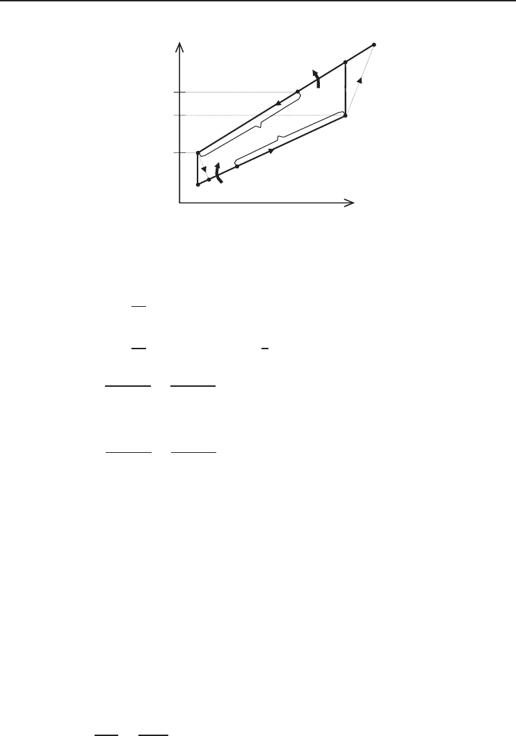
The T –s diagram of the cycle is given in Figure 4.17.
180 Refrigeration Systems and Applications
s
T
1
3
−20 °C
−30 °C
5s
6
4
2s
Q
H
·
Q
Refrig
·
16 °C
Q
regen
2
5
Figure 4.17 Temperature–entropy diagram of gas refrigeration cycle considered in Example 4.5.
(a) From the isentropic relations,
T
2s
= T
1
P
2
P
1
(
k−1
)
/k
=
(
253 K
)(
4
)
0.4/1.4
= 376.0K
T
5s
= T
4
P
5
P
4
(
k−1
)
/k
=
(
243 K
)
1
4
0.4/1.4
= 163.5K
η
T
=
h
4
− h
5
h
4
− h
5s
=
T
4
− T
5
T
4
− T
5s
−−−→ T
5
= T
4
− η
T
(
T
4
− T
5s
)
= 243 −
(
0.84
)(
243 − 163.5
)
= 176.2K
η
C
=
h
2s
− h
1
h
2
− h
1
=
T
2s
− T
1
T
2
− T
1
−−−→ T
2
= T
1
+
(
T
2s
− T
1
)
/η
C
= 253 +
(
376.0 − 253
)
/0.82 = 402.9K
From an energy balance on the regenerator,
˙mc
p
(
T
3
− T
4
)
=˙mc
p
(
T
1
− T
6
)
−−−→ T
3
− T
4
= T
1
− T
6
or
T
6
= T
1
− T
3
+ T
4
= 253 − 289 + 243 = 207 K
The rate of refrigeration, the net power input and the COP are
˙
Q
L
=˙mc
p
(T
6
− T
5
) = (0.45 kg/s)(1.005 kJ/kg · K)(207 − 176.2) K = 13.91 kW
˙
W
net
=˙mc
p
[(T
2
− T
1
) − (T
4
− T
5
)]
= (0.45 kg/s)(1.005 kJ/kg · K)[(402.9 − 253) − (243 − 176.2)]K
= 37.62 kW
COP =
˙
Q
L
˙
W
net
=
13.91
37.62
= 0.370