Egerton R.F. Electron Energy-Loss Spectroscopy in the Electron Microscope
Подождите немного. Документ загружается.

38 2 Energy-Loss Instrumentation
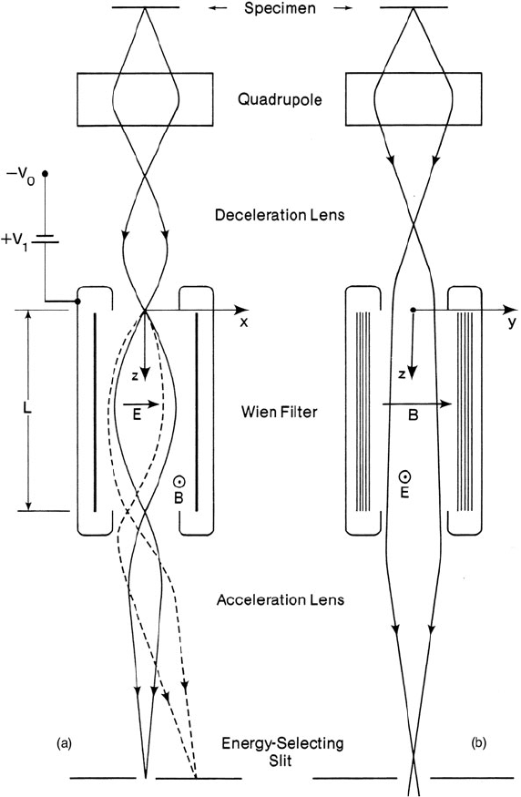
Fig. 2.5 Wien filter spectrometer for a scanning-transmission microscope (Batson, 1985). Electron
trajectories are shown (a) in the dispersive (x–z)planeand(b) in the nondispersive (y–z)plane.
Dashed lines represent electrons that have lost energy in the specimen. A quadrupole lens has been
added to make the system approximately double focusing
magnification (M
x
=−1) is formed at z = L (i.e., after half a revolution), its energy
dispersion being L/(πE
1
) (Curtis and Silcox, 1971). Velocity components along the
y-axis (magnetic field direction) are unaffected by the magnetic and electrostatic
fields, so both the chromatic and achromatic images are actually line foci.
2.1 Energy-Analyzing and Energy-Selecting Systems 39
The Wien filter is generally used with decelerated electrons. In other words, the
filter is operated at a potential −V
0
+ V
1
which is close to the negative potential
−V
0
of the electron source. The positive bias V
1
is obtained from a power supply
connected to the high-voltage line; its value, typically in the range 100–1000 eV,
determines the energy (eV
1
) of the electrons that can move in a straight line through
the filter. The retarding and accelerating fields at the entrance and exit of the filter
act as electrostatic lenses (Fig. 2.5), whose effect must be taken into account in the
design of the system.
Although retardation involves the inconvenience of handling high voltages, it
provides several advantages. First of all, the dispersion at the chromatic focus is
increased by a factor V
0
/V
1
for a given length L of the filter; values of 100 μm/eV or
more are typical. The electrostatic lens at the exit of the filter can be used to project
the spectrum onto the detection plane, with either a decrease or a further increase in
the dispersion, depending on the distance of the final image. Second, the required
magnitudes and stabilities of B and E are reduced and the mechanical tolerances of
the polepieces and electrodes are relaxed. Third, because the electron velocity for
straight-line transmission depends on V
1
rather than V
0
, fluctuations and drift in V
0
do not affect the energy resolution. This factor is particularly important where high
resolution must be combined with long recording times, for example, when record-
ing inner-shell losses using a field-emission STEM (Batson, 1985). A Wien filter
used in conjunction with a monochromator (Section 2.1.4) achieved an energy reso-
lution of 5 meV for 30-keV electrons (Geiger et al., 1970), yielding spectra showing
vibrational and phonon modes of energy loss (Fig. 1.9). These vibrational modes
can be studied by infrared absorption spectroscopy but EELS offers the potential of
much better spatial resolution.
Because the system just discussed does not focus in the y-direction, the energy-
loss spectrum is produced as a function of distance along a straight line in the
entrance plane, this line being defined by an entrance slit. If a diffraction pattern
(or a magnified image) of the s pecimen is projected onto the slit plane, using the
lenses of a CTEM, the final image will contain a map of electron intensity as
a function of both energy loss and scattering angle (or specimen coordinate). A
two-dimensional sensor placed at the final-image plane can therefore record a large
amount of information about the specimen (Batson and Silcox, 1983).
The Wien filter can become double focusing if either E or B is made nonuni-
form, for example, by curving the electric field electrodes, by tilting t he magnetic
polepieces to create a magnetic field gradient, or by shaping both the electric and
magnetic fields to provide a quadrupole action (Andersen, 1967). The device is then
suitable for use as an imaging filter in a fixed-beam TEM (Andersen and Kramer,
1972). Aberrations of the filter can be corrected by introducing multipole elements
(Andersen, 1967; Martinez and Tsuno, 2008).
2.1.4 Electron Monochromators
Besides being dependent on the spectrometer, the energy resolution of an energy
analysis system is limited by energy spread in the electron beam incident on
40 2 Energy-Loss Instrumentation
the specimen. If the electrons are produced by a thermionic source operated
at a temperature T
s
, the energies of the electrons leaving the cathode follow a
Maxwellian distribution, whose full width at half maximum (FWHM) is E
s
=
2.45(kT
s
) (Reimer and Kohl, 2008). For a tungsten filament whose emission surface
is at a temperature of 2800 K, E
s
= 0.6 eV; for a lanthanum hexaboride source at
1700 K, E
s
= 0.3 eV. Values are lower for Schottky and field-emission sources.
2.1.4.1 The Boersch Effect
The energy spread E
0
measured in an electron microscope is always larger than
E
s
, the discrepancy being referred to as the Boersch effect, since Boersch (1954)
first investigated the dependence of the measured spread on physical parameters of
the electron microscope: cathode temperature, Wehnelt electrode geometry, Wehnelt
bias, accelerating voltage, vacuum conditions, and the deployment of magnetic and
electrostatic lenses. He found that E
0
increases with the emission current and is
further increased when the beam is focused into a crossover. Subsequent experi-
mental work (Martin and Geissler, 1972; Ditchfield and Whelan, 1977; Bell and
Swanson, 1979) confirmed these findings.
When electrons are rapidly accelerated to an energy E
0
, their energy spread δE
remains unaltered, in accordance with the conservation of energy. However, the
axial velocity spread δv
z
is reduced as the axial velocity v
z
increases, since (nonrela-
tivistically) δE = δ(m
0
ν
2
z
/2), giving δv
z
= E
s
/(m
0
v
z
). The equivalent axial beam
temperature attained is T
z
= (kT
s
/E
0
)T
s
(Knauer, 1979) and is very low (<0.1 K)
for E
0
> 10 keV. If the electrons spend enough time in sufficiently close proximity
to one another, so that they interact via Coulomb forces, the difference between the
axial and transverse temperatures is reduced, raising δv
z
and increasing the mea-
sured energy spread. This is known as the “thermal” Boersch effect; the resulting
value of E
0
depends on the path length of the electrons and on the current density
(Knauer, 1979).
In addition, electrons that are focused into a crossover can suffer “collision
broadening” through interaction between their transverse velocity components. The
energy broadening depends on the current density at the crossover and on the diver-
gence angle (Crewe, 1978; Knauer, 1979; Rose and Spehr, 1980). The beam current
is highest within the electron gun, so appreciable broadening can occur at a gun
crossover. A cold field-emission (CFEG) source provides the lowest energy spread
(0.3 eV) at low emission currents (<10 nA) but E
0
increases to as much as 1 eV at
100 nA emission, due to Coulomb interaction of electrons just outside the tip (Bell
and Swanson, 1979).
2.1.4.2 Types of Monochromator
The Wien filter offers a high dispersion and good energy resolution (a few mil-
lielectron volts) when operated with low-velocity electrons (Section 2.1.3). It can
therefore be used to produce an incident beam of small energy width i f an energy-
selecting aperture is placed in an image of its chromatic focus (Boersch et al., 1962,
2.1 Energy-Analyzing and Energy-Selecting Systems 41
1964). A second Wien filter (after the specimen) can act as an energy analyzer,
making possible energy-loss spectroscopy of vibrational modes (Boersch et al.,
1962; Katterwe, 1972; Geiger, 1981). An energy resolution below 6 meV was
eventually achieved at 30-keV incident energy.
For analysis of small areas of a TEM specimen, a higher accelerating voltage
is useful and a field-emission source maximizes the fraction of electrons allowed
through the monochromator (this fraction is approximately the required resolution
divided by the energy width of the source). A JEOL-1200EX instrument fitted with
two retarding Wien filters and operated at 80 kV achieved an energy resolution
of typically 80 meV (Terauchi et al., 1994) or down to 30 meV for energy losses
below 5 eV. The microscope accelerating voltage was applied to the analyzing filter
to decelerate the electrons, so high-voltage fluctuations were compensated in this
design.
An alternative strategy is to place the monochromator within the electron gun,
where high dispersion is possible because the electrons have undergone only a lim-
ited amount of acceleration. Mook and Kruit (2000) designed a short Wien filter
for a high-resolution field-emission STEM (Batson et al., 2000, 2001). Its small
length (4 mm) reduced the collision-broadening effect but resulted in a low energy
dispersion (D≈4 μm/eV) for the 800-eV electrons passing through the filter, requir-
ing a very narrow (200 nm) energy selecting to achieve an energy spread in the
50–100 meV range.
For FEI microscopes, Tiemeijer et al. (2001) developed a longer (50 mm) gun
monochromator. Electrons are dispersed and then accelerated before reaching the
energy-selecting slit, making the latter less sensitive to electrostatic charging. The
system has demonstrated a resolution down to 100 meV at low beam current.
The design of Tsuno (2000) is a double Wien filter in which the second half of the
filter compensates for energy broadening within the energy-selecting slit. This pro-
cedure increases the electron-optical brightness by typically a factor of 3 compared
to the single Wien filter design. Since electrons are removed by the energy-selecting
slit, the beam current is still reduced, by a factor about equal to the improvement in
energy resolution. Tsuno et al. (2005) have reported that a Wien filter is capable of
acting as both a monochromator and a lens aberration corrector.
The monochromator design of Rose (1990) is an electrostatic version of the
omega filter. An energy-selecting slit is placed at its mid-plane (equivalent to O
2
in
Fig. 2.4) and the second half of the filter compensates for energy dispersion within
the s lit, optimizing the source brightness. This design was commercialized by CEOS
GmbH and used in the Zeiss SESAM microscope, where it has demonstrated an
energy resolution below 0.1 eV in conjunction with the MANDOLINE energy fil-
ter. Advantages of the electrostatic design include low drift (absence of magnetic
hysteresis effects) and avoidance of a high-stability current supply running at high
potential. Disadvantages are its more complex electron optics and its fixed disper-
sion: the width of the energy-selecting slit must be changed in order to vary the
energy resolution.
A gun monochromator does not compensate for instabilities of the high-voltage
supply and the same is true for designs that use the microscope’s high voltage to
42 2 Energy-Loss Instrumentation
decelerate the electrons inside the monochromator. Unless this same voltage supply
is used to decelerate electrons within the spectrometer, superior design of the high-
voltage supply is necessary to achieve 0.1-eV energy resolution (Tiemeijer et al.,
2001). Such resolution under practical conditions has also required improved spec-
trometer design (Brink et al., 2003) and careful attention to minimizing magnetic
fields in the microscope environment (Muller and Grazul, 2001). Slow drift can be
compensated by storing multiple readouts of the spectrum and shifting them under
computer control; even with no monochromator, this technique has yielded a spec-
tral resolution of 0.3 eV (Kimoto and Matsui, 2002) and a precision of 0.1 eV for
recording ionization edges (Potapov and Schryvers, 2004).
Krivanek et al. (2009) designed a system employing two purely magnetic non-
decelerating filters for the monochromator and analyzer, as shown in Fig. 2.6a.The
monochromator is an alpha filter with an energy-selecting slit at its mid-point, the
second half of the filter canceling the dispersion of the first half. It uses the same
current as the analyzer, so that the latter tracks the energy selected by the monochro-
mator, current drift having no effect on the selected energy. Current absorbed by the
two halves of the energy-selecting slit is used as feedback to the high-voltage gen-
erator so that the beam remains centered on the slit (Kruit and Shuman, 1985a).
Quadrupoles placed before and after the monochromator slit magnify the disper-
sion from 0.3 μm/eV to about 200 μm/eV,soa2-μm slit would select 10 meV
energy width; see Fig. 2.6b. First- and second-order prism focusing is provided
by quadrupole and sextupole lenses, rather than by tilt and curvature of the pole-
piece edges. The sextupoles are also designed to correct for chromatic aberration
of the probe-forming condenser lenses. For core-loss analysis, monochromation i s
less essential, so the alpha-filter field could be canceled by diverting the current into
separate windings, allowing a straight-line path through the system but preserving
the same heat dissipation (to avoid temperature change and mechanical drift). The
energy resolution would then be ≈0.3 eV, assuming a cold field-emission source
running at 200 kV.
2.1.4.3 Dispersion Compensation
One disadvantage of a conventional monochromator system is that the monochro-
mator reduces the beam current by a large factor if the energy spread of the electron
source (including the Boersch effect) greatly exceeds the required energy resolution.
Low beam implies longer recording times. A remedy is to eliminate the energy-
selecting slit of the monochromator and use a completely symmetrical system of
monochromator and analyzer.
For example, if the length of a Wien filter is extended to a value 2L =
2πγm
0
E/eB
2
,anachromatic focus is formed at the exit plane, as discussed i n
Section 2.1.3. Because the final image is achromatic, its width is independent of
the incident energy spread E
0
, a result of the fact that the chromatic aberration of
the second half of the system exactly compensates that of the first half. If a specimen
is now introduced at the chromatic focus (z = L), the resulting energy losses pro-
vide an energy-loss spectrum at z = 2L but the width of each spectral line remains
2.1 Energy-Analyzing and Energy-Selecting Systems 43
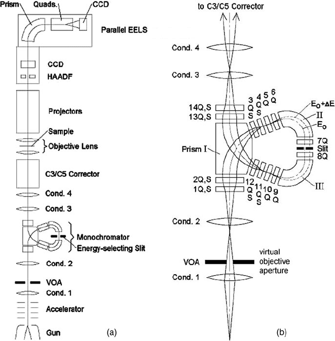
Fig. 2.6 (a) Design of a monochromated TEM in which energy drift is minimized by using the
same excitation current for both the monochromator and spectrometer and where intensity drift is
minimized by feedback from the monochromator slit, so that the beam remains centered at the slit.
(b)Designoftheα-filter monochromator, incorporating three magnetic prisms, quadrupoles (Q),
and sextupoles (S); electrons travel upward from a crossover provided by the condenser 1 lens.
From Krivanek et al. (2009), courtesy of the Royal Society, London
independent of the value of E
0
. In addition, second-order aperture aberrations of
the second half cancel those of the first, so the energy resolution of the system (if
perfectly symmetrical) depends only on higher order aberrations and the object size
of the electron source. In practice, the two halves of the double Wien filter can be
separated by a short distance (to allow room for inserting the specimen) but great
care has to be taken to keep the system symmetrical. An experimental prototype
based on this principle (Andersen and Le Poole, 1970) achieved an energy resolu-
tion of 50 meV (measured without a specimen) using 10-keV transmitted electrons.
Scattering in the sample degraded this resolution to about 100 meV but a transmitted
44 2 Energy-Loss Instrumentation
current of up to 0.1 μA was available. The system can be made double focusing at
the chromatic image by using two independently excited field coils in each Wien fil-
ter (Andersen, 1967), thereby reducing the y-spreading of the beam at the specimen.
Some spreading in the x-direction is unavoidable, because of the energy spread of
the electron s ource and the dispersion produced by the first Wien filter, and would
limit the spatial resolution of analysis.
The same principle (known as dispersion compensation or dispersion matching)
has been employed in nuclear physics, the target being placed between a pair of
magnetic sector spectrometers which bend a high-energy beam of electrons in the
same direction (Schaerf and Scrimaglio, 1964). It has been applied to reflection
spectroscopy of low-energy (e.g., 5 eV) electrons, using two identical spherical
electrostatic sectors (Kevan and Dubois, 1984).
Instead of a monochromator, it would be attractive to have a high-brightness
electron source with low energy width. Fransen et al. (1999) examined the field
emission properties of individual multiwall carbon nanotubes, mounted on the end
of a tungsten wire. In ultrahigh vacuum, the emission was highly stable (less than
10% variation in 50 days) even without “flashing” the tip. Energy widths in the
range 0.11–0.2 eV were measured, the source brightness being roughly equivalent
to that of a cold tungsten field emitter. Subsequent work has confirmed that high
electron-optical brightness may be achievable from a carbon nanotube (De Jonge
et al., 2002); a value of 6 × 10
9
A/cm
2
/sr
1
at 200 kV, together with good stability,
has been reported (Houdellier et al., 2010).
2.2 Optics of a Magnetic Prism Spectrometer
As discussed in Section 2.1.1, a magnetic prism spectrometer produces three effects
on a beam of electrons: bending, dispersion, and focusing. Focusing warrants the
most attention, since the attainable energy resolution depends on the width of the
exit beam at the dispersion plane. Provided the spatial distribution of the magnetic
field is known, the behavior of an electron within the spectrometer can be predicted
by applying equations of motion, based on Eq. (2.1), to each region of the trajectory.
Details are given in Penner (1961), Brown et al. (1964), Brown (1967), and Enge
(1967). The aim of this section is to summarize the results of such analysis and
to provide an example of the use of a matrix computer program for spectrometer
design.
We will adopt the coordinate system and notation of Brown et al. (1964), widely
used in nuclear physics. For a negative particle such as the electron, the y-axis is
antiparallel to the direction of magnetic field. The z-axis always represents the direc-
tion of motion of an electron traveling along the central trajectory (the optic axis); in
other words, the coordinate system rotates about the y-axis as the electron proceeds
through the magnetic field. The x-axis is perpendicular to the y- and z-axes and
points radially outward, away from the center of curvature of the electron trajecto-
ries. Using this curvilinear coordinate system, the y-axis focusing can be represented
on a flat y–z plane (Fig. 2.2b).
2.2 Optics of a Magnetic Prism Spectrometer 45
The behavior of electrons at the entrance and exit edges of the magnet is simpler
to calculate if the magnetic field is assumed to remain constant up to the polepiece
edges, dropping abruptly to zero outside the magnet. This assumption is known as
the SCOFF (sharp cutoff fringing field) approximation and is more likely to be real-
istic if the gap between the polepieces (measured in the y-direction) is very small.
In practice, the field strength just inside the magnet is less than in the interior, and a
fringing field extends some distance (of the order of the gap length) outside the geo-
metrical boundaries. In the EFF (effective fringing field) model, the z-dependence
of field strength adjacent to the magnet boundaries is specified by one or more
coefficients, leading to a more accurate prediction of the spectrometer focusing.
An important concept is the order of the focusing. Formation of an image is a
first-order effect, so first-order theory is used to predict object and image distances,
image magnifications, and dispersive power, the latter being first order in energy
loss. Second- or higher order analysis is needed to describe image aberration and
distortion, together with other properties such as the dispersion-plane tilt.
2.2.1 First-Order Properties
We first consider the “radial” focusing of electrons that originate from a point object
O located a distance u from the entrance face of a magnetic prism (Fig. 2.2). For
a particular value of u, all electrons that arrive at the center of the magnet (after
deflection through an angle φ/2) are traveling parallel to the optic axis before being
focused by the second half of the prism into a crossover (or image) I
x
located a
distance v
x
from the exit edge. We can regard these particular values of u and v
x
as being the focal lengths f
x
of the first and second halves of the prism, and their
reciprocals as the corresponding focusing powers. In the SCOFF approximation,
these focusing powers are given by (Wittry, 1969)
1/f
x
= [tan(φ/2) − tan ε]/R (2.2)
where ε = ε
1
for the first half of the prism and ε = ε
2
for the second half, ε
1
and
ε
2
being the tilt angles of the prism edges. Note that a positive value of ε reduces
the radial focusing power, leading to longer object and image distances. In this case,
the boundaries of the magnet have a divergent focusing action, whereas the effect
of the uniform field in the center of the magnet is to gradually return the electrons
toward the optic axis, as illustrated in Fig. 2.7.
In contrast, focusing in the axial (y-) direction takes place only at the entrance
and exit of the magnet. Each boundary can be characterized by a focusing power
that is given, in the SCOFF approximation, by
1/f
y
= tan(ε)/R (2.3)
Because 1/f
x
and 1/f
y
change in opposite directions as ε is varied, the entrance-
and exit-face tilts can be chosen so that the net focusing powers in the radial and
46 2 Energy-Loss Instrumentation
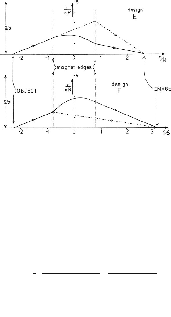
Fig. 2.7 Trajectories of electrons through a magnetic prism spectrometer. Solid lines represent the
component of motion in the x–z plane (first principal section); dashed lines represent motion in the
y–z plane (second principal section). The horizontal axis indicates distance along the optic axis,
relative to the center of the prism. For design E, ε
1
= 0andε
2
= 45
◦
; for design F, ε
1
= 45
◦
and
ε
1
= 10
◦
. From Egerton (1980b), copyright Elsevier
axial directions are equal; the prism is then double focusing. Although not essential,
an approximation to double focusing is generally desirable because it minimizes
the width (in the y-direction) of the image at the energy-selecting plane, making
the energy resolution of the system less dependent on the precise orientation of the
detector about the z-axis.
For a bend angle of 90
◦
, the most symmetrical solution of Eqs. (2.2) and ( 2.3)
corresponds to the double-focusing condition: u = v
x
= v
y
= 2R and tan ε
1
=
tan ε
2
= 0.5 (i.e., ε = 26.6
◦
). In practice, the object distance u may be dictated by
external constraints, such as the location of t he projector lens crossover in an elec-
tron microscope column. The spectrometer will still be double focusing provided
the prism angles ε
1
and ε
2
satisfy the relation (valid in the SCOFF approximation)
tan ε
2
=
1
2
1 −(tan ε
1
+R/u)tanφ
tan ε
1
+R/u +cot φ
−
tan ε
1
−R/u
1 −φ(tan ε
1
−R/u)
(2.4)
As ε
1
increases, the required value of ε
2
decreases, as illustrated in Fig. 2.8.The
image distance v
x
= v
y
= v is given by
v
R
=
tan ε
1
−R/u
1 −φ(tan ε
1
−R/u)
+tan ε
2
−1
(2.5)
2.2 Optics of a Magnetic Prism Spectrometer 47
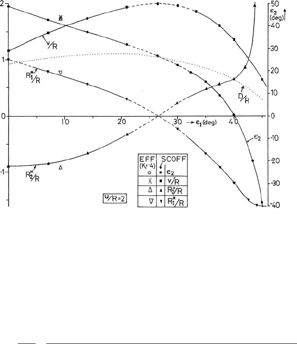
Fig. 2.8 Double-focusing parameters of a magnetic prism, for a fixed object distance (u = 2R)
and bend angle φ = 90
◦
. The curves were calculated using the SCOFF approximation; dashed
lines indicate the region in which correction of second-order aberrations requires excessive edge
curvatures, as determined by Eq. (2.18). One set of points is given for an extended fringing field
(EFF) with K
1
= 0.4. From Egerton (1980b), copyright Elsevier
A large difference between ε
1
and ε
2
leads to stronger focusing, reflected in a shorter
image distance (Fig. 2.8). The dispersive power D = dx/dE
0
at the image plane is
(Livingood, 1969)
D =
R
2γ T
sin φ +(1 −cos φ)(tan ε
1
+R/u)
sin φ[1 − tan ε
2
(tan ε
1
+R/u)] −cos φ(tan ε
1
+tan ε
2
+R/u)
(2.6)
where 2γ T = E
0
(2m
0
c
2
+E
0
)(m
0
c
2
+E
0
), E
0
represents the kinetic energy of elec-
trons entering the spectrometer, and m
0
c
2
= 511 keV is the electron rest energy.
If the spectrometer is to be reasonably compact, the value of R cannot exceed
10–20 cm and D is limited to a few micrometers per electron volt for E
0
= 100 keV.
2.2.1.1 The Effect of Fringing Fields
The SCOFF approximation is convenient for discussing the general properties of a
magnetic prism and is useful in the initial stages of spectrometer design, but does
not provide accurate predictions of the focusing. The effects of a spatially extended
fringing field have been described by Enge (1964) as follows.
First of all, the exit beam is displaced in the radial direction compared to the
SCOFF trajectory. This effect can be taken into account by shifting the magnet
slightly in the +x-direction or by increasing the magnetic field by a small amount.