Ellis,J. Pressure transients in water engineering, A guide to analysis and interpretation of behaviour
Подождите немного. Документ загружается.

102
t = 78.23 s
t = 55.22 s
t = 69.03 s
t = 55.22 s
Closed valve
t = 59.83 s
t = 59.83 s
t = 73.63 s
0
790.3
1580.6
2370.8
3161.1
3951.4
4741.7
5532
6322.2
7112.5
7902.8
8693.1
9483.4
10 273.6
11 083.9
11 854.2
12 644.5
13 434.8
14 225
15 015.3
15 805.6
16 595.9
17 386.2
18 176.4
18 986.7
19 757
Head (mAD)
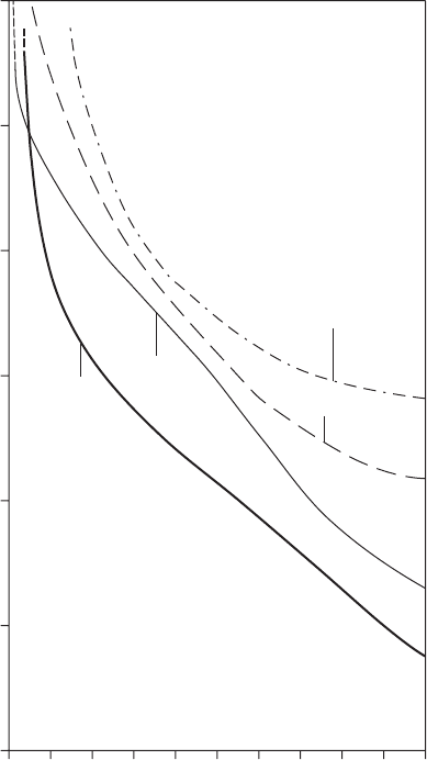
Um Ghafa Water Project
3 s closure of downstream valve
instantaneous hydraulic profiles
55.22 £ t £ 78.23 s
Pipeline profile
Chaina
g
e
(
metres from u
p
stream reservoir
)
80
70
60
50
40
30
20
10
0
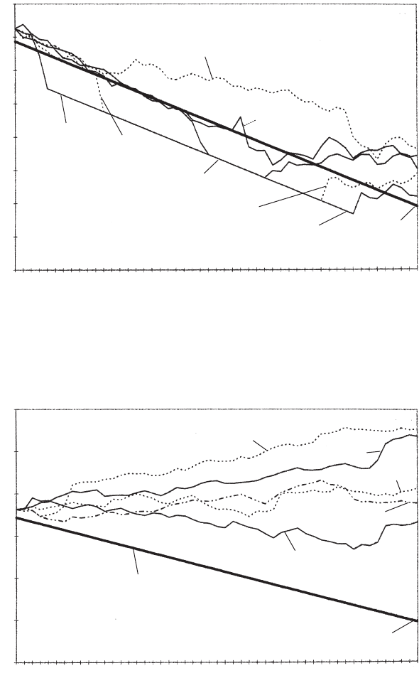
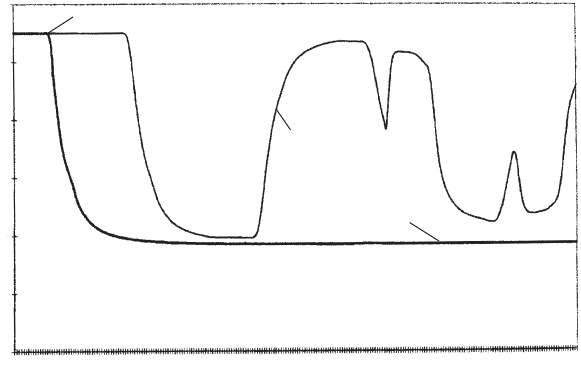
Fig. 8.2c. Progressive collapse of vapour cavities
Closed valve
t = 87.44 s
t = 115.05 s
t = 96.64 s
t = 82.84 s
t = 119.65 s
0
790.3
1580.6
2370.8
3161.1
3951.4
4741.7
5532
6322.2
7112.5
7902.8
8693.1
9483.4
10 273.6
11 083.9
11 854.2
12 644.5
13 434.8
14 225
15 015.3
15 805.6
16 595.9
17 386.2
18 176.4
18 986.7
19 757
Head (mAD)
Um Ghafa Water Project
3 s closure of downstream valve
instantaneous hydraulic profiles
82.84 £ t £ 119.65 s
Pipeline profile
Chaina
g
e (metres from upstream reservoir)
120
100
80
60
40
20
0
Fig. 8.2d. Rising head after cavity removal
Pressure transients in water engineering
downstream reservoir within a military compound with the rate of
flow in the main being controlled using a gate valve just upstream of
the military reservoir.
The wellfield contained an initial set of 30 boreholes, it being the
intention to expand the size and capacity of this field in the future.
Diameter of the 20 km gravity main was chosen to satisfy the
maximum final output from an expanded wellfield. During the first
phase of development it was necessary to operate with the downstream
valve partially closed in order to limit flow in the pipeline to the
first-stage wellfield output of 125 litres/s. The hydraulic gradient, or
piezometric line, for this initial stage was as shown in Fig. 8.2a.
When a valve is being closed from the fully opened position, for a
substantial part of the valve stroke there is little effect upon flow and
head conditions and it is only over the final 15—20% of movement
that substantial deceleration occurs. In the present example however,
the valve was initially set at only 4.5% open and when the valve
closure occurs from this position it will impose important flow and
head variations on the water from the onset of movement.
To illustrate hydraulic transient behaviour, consider events during
and after a valve closure lasting just 3 s. The corresponding time to
close the valve from fully opened would be 67 s.
The compression wave generated by closure travels upstream
through the water-filled pipeline at an acoustic velocity calculated to
be 1113 m/s, with the front of the pressure wave reaching the upstream
reservoir after 17.75 s — that is, L=a seconds from commencement of
valve closure. Figure 8.2a shows successive positions of this wave
front between times 4.6 s and 18.41 s, by which time the wave has
reached the reservoir and commenced to be reflected.
It will be noted that head rise at the valve does not cease after the
final valve closure at 3 s but continues to increase, albeit more slowly.
This is due to the initial pressure wave rise being ‘built’ onto the
initial steady flow hydraulic gradient so that piezometric level just
upstream of the valve increases due to attenuation as described in
the previous section.
After reflection from the upstream reservoir, the reflected rarefaction
pressure wave front travels to the now closed valve which it reaches at
2L=a seconds when a relief of pressure starts to occur. Successive
positions of this reflected wave are shown in Fig. 8.4b at times of
27.61 and 32.21 s. On arriving at the valve, the rarefaction wave
causes piezometric level to fall at time 36.82 s until sub-atmospheric
pressure and eventually vapour pressure occurs. Head at the valve
103
Actual pipelines
now ceases to fall. After 2L=a seconds the reflected wave from the valve
travels upstream, reducing pressure along the majority of the pipeline as
shown in Fig. 8.2b at times 41.42 and 46.02 s. However, head does not
remain at vapour pressure near to the valve. Instead an initial hydraulic
gradient equal to the slope of the pipeline is established along these
parts of the line subject to vapour pressure. A quasi free surface flow
is established towards the valve, causing pressure to increase gradually
at the valve and in adjoining parts of the pipeline as shown in Fig. 8.2c
at times 55.22, 59.83 and 69.03 s.
When the rarefaction wave reaches the upstream reservoir after time
3L=a seconds it is reflected into the pipeline in the form of a compres-
sion wave producing a recovery of head. A situation is developed in
which head is increasing along upstream parts of the pipeline as
shown for times 55.22, 59.83 and 69.03 s. At the same time head is
rising over downstream parts near to the closed valve (Fig. 8.2c),
with vapour bubbles being removed as pressure rises. Eventually these
compression waves meet at a point within the system as the final
vapour cavity is removed and a head rise occurs at this point as
shown in Fig. 8.2c at time 73.63 s.
This head rise then spreads both upstream and downstream, pro-
ducing a more general head rise along the pipeline as illustrated in
104
Head (mAD)
Um Ghafa Water Project
3 s closure of downstream valve
time histories of head
Upstream of valve
0.354
4.248
8.142
12.036
15.93
19/824
23.718
27.612
31.508
35.4
39.294
43.188
47.082
50.976
54.87
58.764
62.658
66.552
70.446
74.34
78.234
82.128
86.022
89.916
93.81
97.704
101.596
105.492
109.386
113.279
117.173
8 km from upstream
reservoir
Time (s)
180
160
140
120
100
80
60
40
20
0
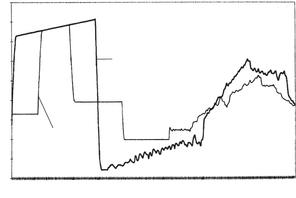
Fig. 8.3. Head plotted against time for 3 s valve closure
Pressure transients in water engineering
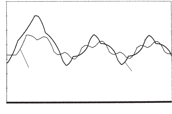
Fig. 8.2d at times 82.84, 87.44 and 96.64 s. Thereafter head starts to
decline as shown for times 115.05 and 119.65 s.
In deciding on an appropriate time of valve closure it is important to
consider not only the initial head rise at the valve on closure but also
the potential for unacceptable pressures being developed following
reflection of the initial pressure wave.
Figure 8.3 shows predicted variations of piezometric level at chainage
8 km from the upstream reservoir and just upstream of the valve for the
3 s valve closure. Figure 8.4 shows corresponding predictions for a more
extended valve closure lasting 2 min.
105
Head (mAD)
Um Ghafa Water Project
2 min closure of downstream valve
time histories of head
Upstream of valve
8 km from upstream
reservoir
Time (s)
0.354
7.06
13.806
20.532
27.258
33.964
40.71
47.436
54.162
60.888
67.614
74.34
81.066
87.792
94.518
101.244
107.97
114.695
121.421
128.147
134.873
141.599
148.326
155.052
161.778
166.504
175.23
181.956
188.682
195.400
202.134
208.80
140
120
100
80
60
40
20
0
Fig. 8.4. Head plotted against time for 2 min valve closure
Actual pipelines
9
Valve operations
The term valve encompasses many different types, each with a wide
range of duties. Valves discussed in this chapter are those located
on a pipeline and through which flow passes during normal opera-
tion. These are often used to control discharge and/or pressure.
Many valves are under operator control using actuators to open and
close the valve at a pre-defined rate. Others may be manually oper-
ated using a handwheel. Still other valves are fitted with control
systems which respond to changes in flow and pressure throughout
the day. These valves may be set to maintain a set upstream or
downstream pressure or to produce a set range of downstream
pressure and flow. Each of these valve patterns has the capability to
initiate hydraulic transients during the process of flow adjustment.
Where a valve is not moving it will merely act as a partial trans-
mitter/reflector of surge effects arising elsewhere in the pipeline
system.
This chapter includes several examples of gravity pipeline systems
in which flow is controlled using valves. Valve operation is one of the
primary sources of pressure transient behaviour. In the majority of
cases discharge is controlled by a valve at the downstream end of the
main. A valve in this position may be called a ‘terminal discharge
valve’. Pressure surges will be developed in the line upstream of the
valve as it is opened or closed. In some instances a valve may be
positioned at some point within a pipeline system with appreciable
lengths of line both upstream and downstream of the valve. A valve
in this position may be called an ‘in-line valve’ with transient effects
produced both upstream and downstream of the valve. Other valves
are the discharge valves just downstream of pumps and the isolating
valves distributed along long pipelines.
106
9.1 Treated water main
The first example concerns a steel gravity main, diameter 1000 mm and
length 16.8 km, with a radically different profile to the uniform profile of
the example in Chapter 8. The pipeline profile undulates considerably
(Fig. 9.1). The water in this pipeline has been treated and so it is a
requirement that minimum pressure should remain positive
throughout. Inflow to the lower reservoir is normally controlled using
float-operated valves which respond to changing level in the receiving
reservoir. In addition, emergency butterfly valves are provided upstream
of the float valves. The function of the butterfly valve is to close in the
event that the float valve does not shut.
Maximum transient pressure caused by butterfly valve closure should
not exceed the peak pressure developed during float valve closure.
107
0 1 2 3 4 5 6 7 8 9 10 11 12 13 14 15 16 17
Maximum piezometric level
during float valve closure
Flow rate = 95.47 Mld when
upstream reservoir is at
top water level (TWL)
Flow rate = 90.92 Mld when
upstream reservoir is at
lowest draw-off (LDO)
Chaina
g
e (km)
TWL
LDO
Head (mAD)
Pipeline profile
140
130
120
110
100
90
80
70
60
50
40
30
20
10
0
Fig. 9.1. Steel gravity main
Valve operations
The head loss characteristic of the butterfly valve and of some other
valves was as shown in Fig. 9.2, where head loss H ¼ K
L
V
2
=ð2gÞ.It
will be noted that changes in K
L
are modest for much of the stroke
from open to shut. Only when the valve has become about 15%
closed does the value of K
L
start to change more rapidly. Unfortunately
the availability of head loss data is more limited towards the more
interesting closed valve end of the stroke. Typically, data curves
obtained from manufacturers terminate around the 10% open position
and it is often necessary to complete the curve down to the closed
108
0 0.1 0.2 0.3 0.4 0.5 0.6 0.7 0.8 0.9 1.0
10 000.0
1000.0
100.0
10.0
1.0
0.1
0.01
Valve
p
osition as a
p
ro
p
ortion of
p
ort stroke
Needle
Butterfly
Gate
Valve head loss coefficient, K
L
Valve head loss characteristics
Submerged discharge
Fig. 9.2. Valve loss coefficients plotted against stroke
Pressure transients in water engineering
position. As the valve door approaches its seat K
L
!1and in compu-
tations a shut valve coefficient of the order of 10
12
is required to reduce
velocity effectively to zero.
Maximum flow rate through the gravity main is dependent upon the
upstream reservoir level while discharge head takes place above the
water level in the downstream service reservoir. Flow rate varied from
90.92 Mld to 95.47 Mld over the range in upstream reservoir elevation.
While primary interest usually centres upon valve closure and the
transient pressures developed as a consequence, it is also advisable to
check pressures occurring during the process of valve opening.
Performing a valve opening analysis avoids the need to establish an
initial steady flow rate and hydraulic gradient. Instead simple initial
static conditions can be set and the valve opened to permit flow to
become established. Figure 9.3 shows the predicted head variation
just upstream of the valve and at the halfway point along the main
for a one-minute valve opening interval. It can be seen how rapidly
the head can fall as the valve is opened over the first 10% or so of its
stroke. In contrast, flow in the pipeline at the valve is predicted to
develop in a stepped manner over an interval of about 4 min (Fig. 9.4).
The rapid fall in head, as the valve starts to open, travels upstream as
a negative pressure wave and it is possible that this wave may cause
109
0.365
3.285
6.205
9.125
12.045
14.965
17.885
20.805
23.725
26.645
29.565
32.485
35.405
38.325
41.245
44.165
47.085
50.005
52.925
55.845
58.785
61.685
64.605
67.525
70.445
73.365
76.285
79.205
82.125
85.045
Time (s)
Head (mAOD)
Start of valve operation
Head variations during 1 min
opening of butterfly valve
Mid-point of main
Upstream of
butterfly valve
125
120
115
110
105
100
95
Fig. 9.3. Head variations during valve opening
Valve operations
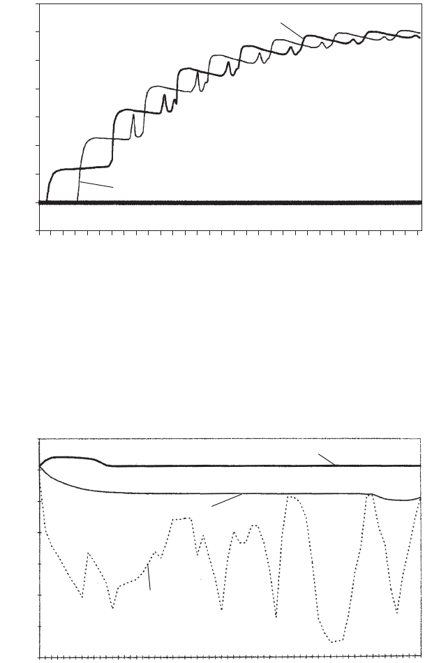
operation of air valves at high points along the pipeline. Figure 9.5
shows the curves of minimum and maximum head during this valve-
opening sequence.
With computer simulation carried out for a sufficient length of time,
essentially steady flow conditions will have been established at the end
110
1.4
1.2
1.0
0.8
0.6
0.4
0.2
0
–0.2
0.365
9.125
17.885
26.645
35.405
44.165
52.925
61.685
70.445
79.205
87.965
96.725
105.485
114.245
123.005
131.765
140.525
149.285
158.045
166.805
175.585
184.326
193.086
201.846
210.606
219.366
228.126
236.886
245.647
254.407
263.167
271.926
Velocity (m/s)
Time (s)
At butterfly valve
At upstream reservoir
Development of velocity in DN 1000 main
for 1 min butterfly valve opening
Fig. 9.4. Flow development after valve opening
Maximum and minimum head in
DN 1000 main 1 min butterfly valve opening
Chaina
g
e (m)
Head (mAOD)
0
835
1671
2508
3342
4177
5012
5848
6401
6968
7818
8669
9235
10 095
10 668
11 529
12 390
13 251
14 112
14 701
15 585
16 469
140
120
100
80
60
40
20
0
Minimum head
Maximum head
Pipeline profile
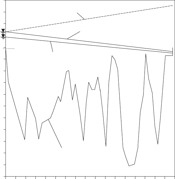
Fig. 9.5. ‘Envelope’ curves of head during valve opening
Pressure transients in water engineering
of computations. Within these computations the hydraulic transients
were predicted to decay asymptotically under the action of pipeline
resistance but with a tendency for small oscillations in head and flow
to persist for an appreciable time. It is up to the user to decide when
these small fluctuations are no longer significant.
Closure of the valve from the fully opened position involves move-
ment of the valve door over a substantial part of the stroke when the
value of K
L
changes only slowly. The corresponding flow and head
changes in the pipeline are modest. Only during the final 10% or so
of closure does K
L
increase rapidly, with large changes of flow and
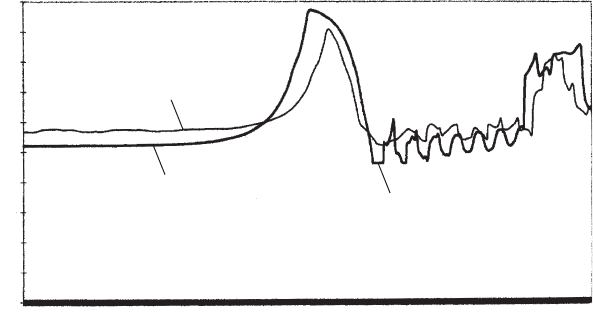
head taking place. Figure 9.6 shows changing head upstream of the
valve and at the mid-point of the main for a 3 min closure. Closure
in a time < 2L=a will produce a head rise which is essentially that
produced by an instantaneous closure, ignoring the effect of attenua-
tion. Velocity decreases only slowly over initial parts of the closure
and then increasingly steeply until the valve is shut. Subsequent reflec-
tion of this initial upsurge can produce minimum head conditions which
cause air valves to open. Figure 9.7 shows maximum and minimum
head falling to the pipeline level at several locations along the
undulating profile. Since head rise is a function of the flow deceleration
dV=dt, it can be seen that the peak inertial head rise will depend upon
the maximum deceleration rate, even although this deceleration only
occurs for a relatively small fraction of the closure time.
111
DN 100 steel gravity main
3 min butterfly valve closure
0.365
12.045
23.725
35.405
47.085
58.765
70.445
82.125
93.805
105.485
117.165
128.845
140.525
152.205
163.885
175.585
187.246
196.926
210.606
222.286
233.966
245.647
257.327
269.006
280.686
292.368
304.045
315.725
327.405
339.064
350.764
362.444
Time (s)
Head (mAOD)
200
180
160
140
120
100
80
60
40
20
0
Head at midpoint of main
Head upstream of valve
Full vacuum upstream of valve
Fig. 9.6. Head variations for 3 min valve closure
Valve operations