Ellis,J. Pressure transients in water engineering, A guide to analysis and interpretation of behaviour
Подождите немного. Документ загружается.

The simplest way to reduce rates of deceleration and thus inertial
head is through extending the time of closure of the valve. For the
present example, Fig. 9.8 shows maximum pressure upstream of the
valve as a function of closure time. To reduce maximum pressure to
112
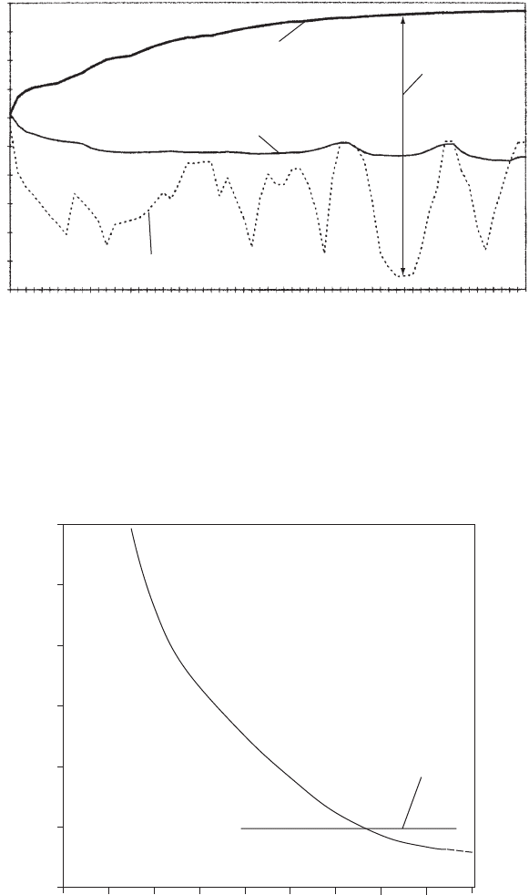
Maximum and minimum head during
3 min butterfly valve closure
0
835
1671
2506
3342
4177
5012
5848
6401
6968
7818
8669
9235
10 095
10 668
11 529
12 390
13 251
14 112
14 701
15 585
16 469
200
180
160
140
120
100
80
60
40
20
0
Chaina
g
e
(
m
)
Head (mAOD)
Maximum head
DN 1000 pipeline profile
Maximum
pressure head
Minimum head
Fig. 9.7. Envelope curves of head for 3 min valve closure
+
+
+
+
+
0 2 4 6 8 10 12 14 16 1
8
Maximum pressure on
float valve closure
Time (min)
Pressure (bar g)
18
17
16
15
14
13
12
Fig. 9.8. Maximum pressure plotted against valve closure time
Pressure transients in water engineering
similar levels obtained during float valve closure requires a valve stroke
time >13 min. Closure intervals can become quite prolonged. This is a
consequence of the need to slow valve movement during the final 10—
20% or so of closure in order to reduce the deceleration rate. This same
slow valve movement also takes place over the larger part of the stroke
when little flow change occurs.
9.2 Improving valve operation
An ideal valve would seek to produce a linear variation of velocity with
stroke. In practice this is very difficult to achieve but some steps can be
taken to improve this relationship by reducing the degree of non-
linearity between velocity and stroke. For example, a reduction in
valve diameter can improve this relationship but at a price. The head
loss through the smaller valve is greater than for a line sized valve so
that maximum flow attainable is reduced.
The flow through a large-diameter pipeline can be split into two or
more smaller-diameter branches before entering a downstream reser-
voir. The valves on each branch will also be smaller. These can be
set to close in sequence so that a more gradual deceleration can be
achieved. It is also easier for an operator to close a smaller valve.
One method of reducing the overall time of valve closure is to utilise
an actuator capable of closing the valve at alternative rates over
different parts of the stroke. For example, it is possible to cause the
valve to close relatively quickly during initial stages of movement, say
from 100% open to 20% open, using 50% of the overall closure time
and to move the valve more slowly from 20% open to shut over the
remaining 50% of closure time. Potentially, using a multi-stage
closure, it would be possible to attain an almost linear deceleration
over the entire valve stroke. An example using two-stage closure is
included in section 9.3.
Common ‘off-the-shelf ’ valves such as gate valves, sluice valves and
butterfly valves have quite unfavourable characteristics as regards surge
control because of the highly non-linear relationship between K
L
and
the valve position (Fig. 9.2).
9.3 Two-stage valve closure
Release of water from a high dam may use a valve which discharges
to a downstream watercourse or into a supply pipeline. Since a
considerable amount of energy is involved it is important to include
113
Valve operations
an emergency closing valve upstream of the terminal discharge valve.
In the event of a pipe burst or failure of the terminal valve, flow will
accelerate within the outlet pipework with velocities of the order of
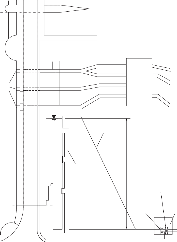
30 m/s being attained. Figure 9.9 illustrates outlet works from a high
dam with emergency closing butterfly valves included. These butterfly
valves (Fig. 9.10) are fitted with a lever and weight to assist closure
114
Valve house
Emergency
butterfly
valve
Valve
house
Spillway
Penstocks
Draw
off
Dam
crest
Downstream
dam face
120 m
Draw-off well
Flow
regulating valve
Burst site
Section through dam
Fig. 9.9. Reservoir outlet arrangement
Pressure transients in water engineering
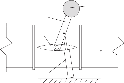
but with an oil-filled piston and cylinder arrangement attached to the
lever limiting rates of movement. The rate of valve closure can be
regulated by altering the orifice through which oil passes while the
valve moves. In this case the orifice arrangement can allow two rates
of movement of the valve. A relatively rapid movement of the valve
was permitted from the 908 position (100% open) down to 98 over
the first 50% of the total closure time. Then a much slower closure
rate was used from 98 open to 08 (shut) for the second 50% of stroke
time.
Closure times from 15 s to 60 s were studied during which the valve
angle changed from 908 (fully open) to 98 in half the time and from 98 to
08 (shut) in the remaining time.
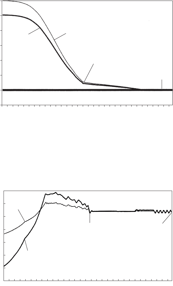
Figure 9.11 shows the variation of velocity during a 30 s closure event
and Fig. 9.12 depicts the changing head upstream of the valve during
closure. It will be noted that maximum head exceeds the static level
by <20 mWG.
Calculations can also be used to predict changing forces and
torques acting upon the valve door. In addition to head loss co-
efficient data, manufacturers can also supply force and torque data as
a function of valve position. This information can be used to establish
the force and its direction, acting on the valve door and from this the
frictional resistance moment offered by the valve shaft as it rotates.
Hydrodynamic torque can also be calculated and when added to the
frictional resistance torque the net closure moment can be found as a
115
Piston and cylinder
Weight
Lever
Valve door
Flow
Fig. 9.10. Emergency closing butterfly valve
Valve operations
function of valve position during closure. This information allows the
manufacturer to design an appropriate lever and weight which is able
to overcome resistance and allow the valve door to close within the
design period.
116
0.02
1.04
2.06
3.08
4.10
5.12
6.14
7.16
8.18
9.20
10.22
11.24
12.26
13.28
14.30
15.32
16.34
17.36
18.38
19.40
20.42
21.44
22.46
23.48
24.50
25.52
26.54
27.56
28.58
29.60
30.621
31.641
Velocity (m/s)
30
25
20
15
10
5
0
–0.5
30 s emergency valve closure
At emergency
butterfly valve
At base of
draw-off well
Valve 10% open
Valve shut
Time (s)
Fig. 9.11. Velocity variations during two-stage valve closure
Valve 10% open Valve shut
0.02
1.00
1.98
2.96
3.94
4.92
5.90
6.88
7.86
8.84
9.82
10.80
11.78
12.76
13.74
14.72
15.70
16.68
17.66
18.64
19.62
20.60
21.58
22.56
23.54
24.52
25.50
26.48
27.46
28.44
29.42
140
120
100
80
60
40
20
0
Time (s)
Head (m)
Base of
draw-off well
Upstream of butterfly valve
30 s emergency valve closure
Fig. 9.12. Head variations for two-stage valve closure
Pressure transients in water engineering
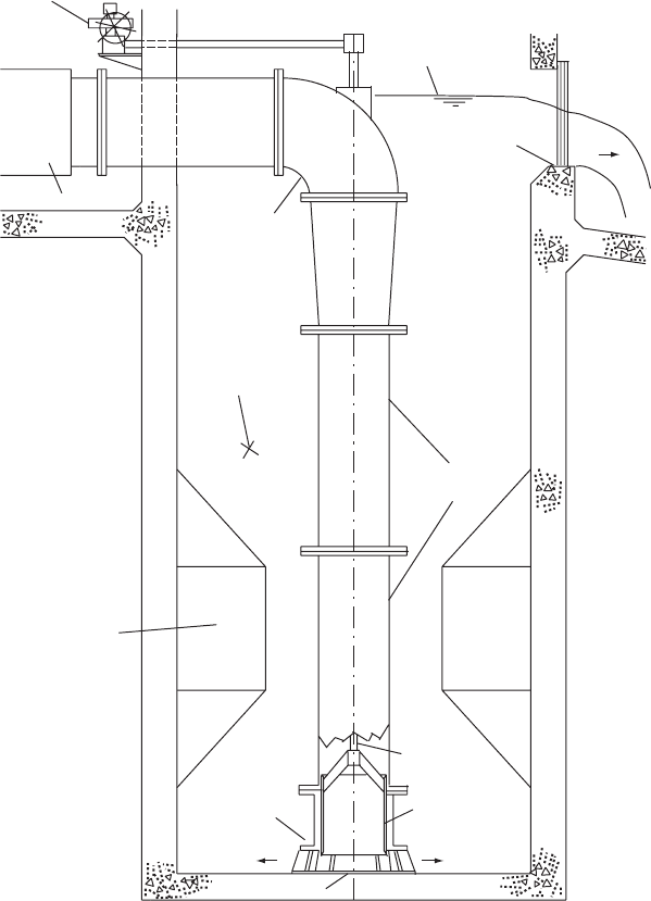
9.4 Submerged discharge valve
It is also possible to improve the relationship between velocity and valve
position by employing a more sophisticated type of valve. One such is
the submerge discharge valve described by Miller (1969) (Fig. 9.13).
The principle of operation is that a ported sleeve, attached to a shaft
and actuator, is moved vertically to control flow passing into a sump
117
M
Corner fillets
Spindle
Moving sleeve
Flowmeter
Inlet bend
Actuator
Water surface
Spillway
Discharge sump
Vertical
downpipe
Baseplate
Valve outlet
Fig. 9.13. Submerged discharge valve
Valve operations
where the energy of flow is dissipated. The port shape can be modified
to suit the circumstances both of the system in which it is installed and
also the range of flows over which the valve is to exercise control. The
port shapes can be altered over time to suit any changes in flow rate as a
scheme is developed. For example, in the early years of a project, flow
may be modest to suit prevailing demands while in later years flow
may have to be increased to meet anticipated increase in demand.
9.5 In-line valves
Two basic purposes can be identified for in-line valves. The most common
is the isolating valve which is normally fully open and remains so except
during periods of maintenance or possibly when an emergency has
occurred which requires the valve to be closed. The second valve applica-
tion is where an actuated valve is used to control and shut off flow within a
pipeline system but where a terminal valve would be impractical. The
method of analysis is the same for each category.
9.5.1 Isolating valves
While hydraulic transient analyses are commonly associated with
operation of terminal discharge valves for instance, some attention
should be paid to the action of isolating valves installed at intervals
on longer pipelines and also on branch pipelines. These valves are
included for the primary purpose of allowing sectional maintenance
without dewatering the entire system. Should an emergency arise,
such as a pipe burst, flow within the upstream pipeline will accelerate
towards the burst site. Isolating valves in the network adjacent to the
burst and in particular on the supply side of the system, must be able
to close safely and without causing further bursts.
Sluice valves and more recently butterfly valves are considered appro-
priate for this application. The butterfly valve is easier to operate than a
comparable sluice valve under similar conditions. For ease of manual
operation, handwheel diameter d has been given by Bartlett (1978) as:
d ¼ 6
p
D
with D being pipe diameter. The practical continuous handwheel opera-
tion rate is around 20 rpm. Closing a valve against an unbalanced head
may require spur gearing. In one example, McCrone (undated) quotes
3:1 gearing to close a sluice valve against a differential head of
40 mWG. The total number of turns till closure is 144, giving a 7.2 min
118
Pressure transients in water engineering
closure interval. The butterfly valve by contrast has a standard 70:1 worm
gear needing only 17
1
2
turns to close through 908. Closure time for the
butterfly valve is only 0.87 min. Surges produced by these valves were
93 m for the sluice valve and 135 m for the butterfly valve. These repre-
sent pressures 232% and 337% higher than the allowable maximum.
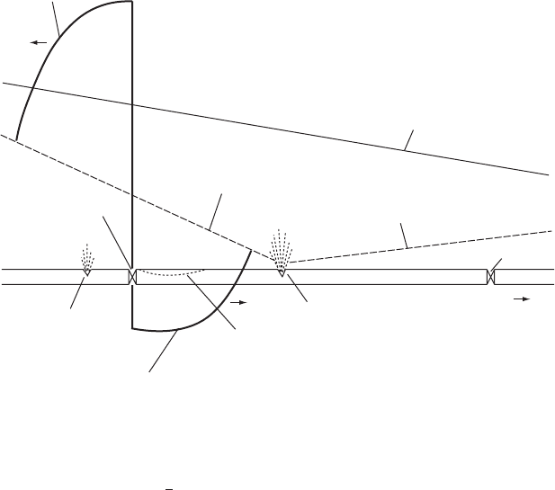
The effect of a too rapid isolating valve closure may be to produce
additional pipe bursts upstream due to the allowable peak pressure
having been exceeded. Also on the downstream side of the valve,
pressure will fall, potentially causing vacuum pressures which may
cause a pipe to buckle and collapse (Fig. 9.14).
9.5.2 Actuated valve
Figure 9.15 shows a water transfer system in which flow which has
previously been pumped from a reservoir to a break pressure chamber
(BPC) travels under gravity to a connection with a pumping main.
An in-line valve has been included upstream of the connection to
the second main. Flow passing through the in-line valve enters the
second main and continues to flow under gravity to augment the
volume stored in a second reservoir. The in-line valve is of a needle
119
Compression wave travelling upstream
when isolating valve is closing
Initial flow direction
Initial pipe burst
Possible pipe collapse due to
low pressure after valve closure
Rarefaction wave travelling downstream
when isolatin
g
valve is closin
g
Possible pipe burst
due to high pressure
after valve closure
Gradient flattens/reverses post-burst
Gradient steepens
post-burst
Isolating valve
Isolating valve
Steady flow hydraulic
gradient pre-burst
Fig. 9.14. Emergency closure of an in-line valve
Valve operations
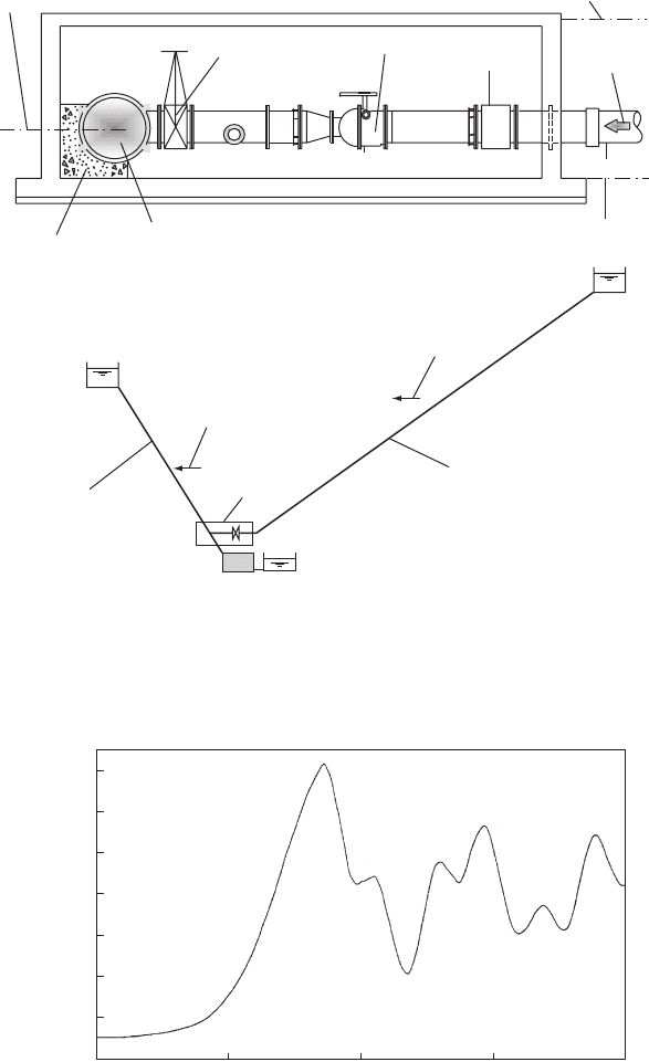
120
Ground level = 10.8 mAOD
C.L. = 8.75 mAOD
Floor level = 8.15 mAOD
Flow direction
Inlet main
Flowmeter
Needle valve
Isolating valve
Downstream main
Thrust block
Gravity transfer main
Receiving
reservoir
Flow direction
Flow direction
Valve
chamber
Downstream main
PS
(
idle
)
Suction tank
BPC
M
M
M
Fig. 9.15. In-line needle valve
Head upstream of needle valve –
1.8 min closure at a flow rate of 16 Mld
180
160
140
120
100
80
60
Time (min)
Head (mAOD)
0 1 2 3
Fig. 9.16. Head upstream of needle valve for 1.8 min closure
Pressure transients in water engineering
type whose head-loss characteristic is shown in Fig. 9.2 and which is
installed in a chamber as shown in Fig. 9.15.
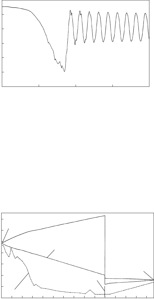
When the valve is closed over a time of 110 s, head upstream of the
valve increases smoothly to a maximum as depicted in Fig. 9.16. After
wave reflection from the BPC, head falls to produce an irregular
oscillation. On the downstream side of the valve, head falls during
valve closure (Fig. 9.17). After valve closure and wave reflection, head
largely recovers and a fairly regular oscillation is developed. The timescale
of oscillations shown in Figs 9.16 and 9.17 are indicative of the respective
lengths of pipeline upstream and downstream of the closed in-valve.
Overall variations in head through the system can be seen in Fig. 9.18.
121
Head downstream of needle valve –
1.8 min closure at a flow rate of 16 Mld
Head (mAOD)
45
42
39
36
33
30
0 1 2 3
Time (min)
Fig. 9.17. Head downstream of needle valve for 1.8 min closure
0 1 2 3 4 5 6 7 8 9 10 11 12 13 14
175
150
125
100
75
50
25
Head (mAOD)
Chaina
g
e (km)
BPC
Downstream
reservoir
Needle valve chamber
Pipeline profile
Envelope curves of max. and
min. head for 1.8 min closure
Flow rate = 16 Mld
Fig. 9.18. Envelope curves for 1.8 min valve closure
Valve operations