Henini M. Handbook of Self Assembled Semiconductor Nanostructures for Novel devices in Photonics and Electronics
Подождите немного. Документ загружается.

Slow Oscillation and Random Fluctuation in Quantum Dots: Can we Overcome? 379
opportunity to study G–V in detail without the need to zero in on a QD as it is done in photolumi-
nescence studies; this will be detailed in the next section.
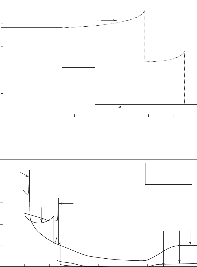
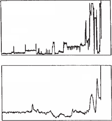
Figure 12.11 shows slow conductance oscillation [5] . The top Figure shows steps with oscil-
latory sharp peaks vs applied bias voltage. In the middle Figure, at bias V 11.95 V, closer to
the top step, the on-time is longer. G oscillates between 260 and 420 with Δ G 1 6 0 μ S. In the
bottom fi gure, at bias V 11.85, closer to the bottom step, on-time is very short, G oscillates
T 300 K
500
400
300
200
100
0
11.7
11.6 11.5
11.4
11.3
Gate bias (Volt)
Conductance at 1MHz (μs)
Figure 12.9 Typical step-like G–V with hysteresis at 300 K. The conductances 40, 205, 380 μ S correspond to
Δ G 40, 165, 185 μ S G
0
, 4 G
0
, 5 G
0
[5] , [15] , and Li’s thesis [16] .
c
b
a
abc
S
a
1.6 10
5
cm
2
S
b
1.0 10
4
cm
2
S
c
5.2 10
4
cm
2
800
600
400
200
0
14 12 10 8 6 4 20
Gate bias (volt)
Conductance at 1 MHz (μs)
Figure 12.10 G–V with three contact areas: lower, 1.6, middle, 10, and upper 52 1 0
5
c m
2
. Conductance for
all peaks and steps are same for all contacts. Conductance near V 0 is caused by trappings.
CH012-I046325.indd 379CH012-I046325.indd 379 6/24/2008 3:37:20 PM6/24/2008 3:37:20 PM
380 Handbook of Self Assembled Semiconductor Nanostructures for Novel Devices in Photonics and Electronics
between 260 and 460, with Δ G 2 0 0 μ S, this indicates that the origin of the oscillation with peri-
ods 0.2 s to more than 20 s is caused by trap-induced Coulomb blockade.
Figure 12.12 shows another sample with oscillation period 0.3 s [18, 19] . In the past these
data were put to one side because the oscillations indicated a serious problem with trapping in
the QD structure. However, it is now known that even the best InP QDs and InAs QDs have simi-
lar problems of instability due to trapping.
Before I deal with optical instability of QDs, I want to show the effect of light, converting a
small conductance peak to a huge peak as shown in Fig. 12.13 with a slight shift in the position
of the steps [20, 21] . The shift may be due to heating; however, the appearance of a very large
conductance peak may be caused by light-induced passivation of defects. Using various fi lters
and a tungsten light, it was discovered that IR below the band gap of Si has no effect.
Figure 12.14 shows a random telegraph-like conductance spectrum obtained fi rst by Ding
[20] . As pointed out before, we eventually learn how to control various types of QDs by control-
ling the power and time of electrical forming in the forward part of the I–V.
The type of samples we fabricated using various annealing and electrical forming results in
selecting a simple confi guration having a current fi lament consisting of only one silicon dot. As
pointed out in [5] whenever eV
1
in Eq. 12.4 is aligned with E
F
, the energy E
1
e
2
/2 C , E
1
2 e
2
/
2 C , etc. includes charging the capacity C , referred to as Coulomb blockade by Likharev [23] ,
Time (second)
01020304050607080
Time (second)
Gate bias (volt)
01020304050607080
(c) V 11.85 V
(b) V 11.95 V
(a) Ramp rate 1 mV/s
sample #1
500
400
300
200
100
0
500
400
300
200
100
0
500
400
300
200
100
bc
0
Conductance at 1 MHz (μs) Conductance at 1 MHz (μs) Conductance at 1 MHz (μs)
12.0 11.9 11.8 11.7 11.6
Figure 12.11 Slow conductance oscillation. Top : G vs V , Middle : G vs time at V –11.95 V, closer to the next
step Bottom : V –11.85 V, closer to the previous step.
CH012-I046325.indd 380CH012-I046325.indd 380 6/24/2008 3:37:20 PM6/24/2008 3:37:20 PM
Slow Oscillation and Random Fluctuation in Quantum Dots: Can we Overcome? 381
which is simply electrostatics. When trapping by a defect is present, the fi rst current jump occurs
at an applied voltage V
a
V
1
Q/C . Suppose an electron is captured resulting in Q e ( n 1 ) ,
an additional voltage of e/C is necessary to maintain resonant tunnelling. Because the applied
bias is fi xed, the conductance will jump down to a lower value. Conversely, whenever an electron
is emitted from a trap, the charge Q returns to Q en , the potential at the QD drops back so that
the energy state involved is again aligned with the Fermi level of the contact at V
1
, causing the
conductance to jump back to a higher value. Therefore the period is the sum of the electron cap-
ture and emission time constants. In this picture, oscillation is the result of a fl ip-fl op between
two charge states involving exchange with a defect. Alternately, by assuming that a non-con-
ducting state is weakly coupled to a conducting state via an oxide barrier 3.2 eV, for a period of
32 34
26
18
10
2
24
16
8
0
Figure 12.12 Typical conductance oscillation shows up in less than 5% of the devices with Si QD formed by
crystallization from the a -Si phase.
600.0
500.0
400.0
300.0
200.0
100.0
0.0
16.0 14.0 12.0 10.0 8.0 6.0 4.0 2.0 0.0
Bias voltage (v)
Figure 12.13 Conductance versus bias voltage without light (solid) and with light (dotted). IR irradiation below
the band gap of silicon has no effect.
CH012-I046325.indd 381CH012-I046325.indd 381 6/24/2008 3:37:21 PM6/24/2008 3:37:21 PM
382 Handbook of Self Assembled Semiconductor Nanostructures for Novel Devices in Photonics and Electronics
10 s, it is necessary that the barrier width 15 nm. Since the total layer thickness is 15 nm, the
origin of the switching is more likely due to a defect state located near a conducting QD rather
than a similar but non-conducting QD state. Conduction peaks have been reported by resonant
tunnelling via bound states of a single donor in a quantum well [24] , which is not too different
from our cases.
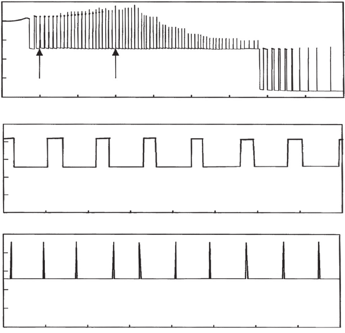
In Figure 12.15a the sweeping rate of 1 mV/s for the applied bias is used for conductance ver-
sus the bias voltage near and before a peak. The voltage separation between points b and d in (a) is
50 mV corresponding to 50 s. At a period varying from 0.2 s to 5 s, there should be 250 to 10
oscillations. In other words, most of the oscillatory peaks shown in Figure 12.15a are oscillations
11.45 11.55 11.65 11.75
Bias voltage (V)
1.8c04
2.0c04
2.2c04
2.4c04
2.6c04
Conductance (mho)
Figure 12.14 Conductance versus bias voltage shows telegraph-like noise. At a fi xed voltage, the variation in time
is an like all those we have shown as oscillations or oscillatory switching, rather it is a typical noise-like spectrum.
Unpublished thesis by Chen Ding (1994).
0
100
0
200
300
400
500
1234
Time (second)
5678
01234
Time (second)
56
(d) V 11.814 V(b) V 11.86 V
(c) V 11.855 V(a) Ramp rate 1 m V/s
sample #2
12.0 11.9 11.8 11.7
78
010203040
Time (second)
50 60 70 80
Conductance at 1 MHz (μs)
100
0
200
300
400
500
Conductance at 1 MHz (μs)
100
0
200
300
400
500
Conductance at 1 MHz (μs)
100
0
Gate bias (Volt)
200
300
400
500
Conductance at 1 MHz (μs)
Figure 12.15 Conductance spectrum near and before a peak is shown in (a). At fi xed voltages, (b)–(d), oscillation
with time is detailed. Taken by X. Li, unpublished [25] .
CH012-I046325.indd 382CH012-I046325.indd 382 6/24/2008 3:37:22 PM6/24/2008 3:37:22 PM
Slow Oscillation and Random Fluctuation in Quantum Dots: Can we Overcome? 383
in time rather than with bias voltage! The period of oscillation is reduced when approaching the
conductance peak as shown in (b) and (c). Oscillation is more complex in (d) where the number
of electrons involved in jumping back and forth varies between 4 and 8 while in (b) nd (c) the
number appears to be fi xed at 8 [25] . At this stage, emphasize should be that the energy states
are rather different from the central fi eld problem typifi ed in atomic hydrogen, having 1 s, 2 s,
2 p, etc. As shown in Figure 12.4 , the lowest state of a quantum cube has a set of three quantum
numbers, (111), but a quantum sphere of Si has (011), in addition to the other complications
arising from the directional effective masses. These considerations, together with the degeneracy
factor, are very complex.
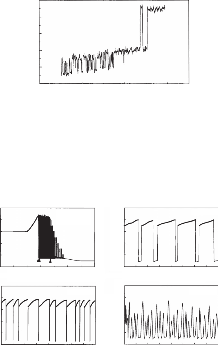
Figure 12.16 shows telegraph-like noise spectra of complex current fl uctuation prior to oxide
breakdown due to discrete multilevel switching [22] . Note that the spectra are also voltage
dependent. Actually, I do not like to use the word noise, because the broad feature of the signal is
very different from random thermal noise. Instability is probably a better description. As long as
the majority of samples are bad samples and are rejected, our selection process does have mer-
its, which is not so different from annealing in steam to reduce the interface density of the MOS
capacitors, or even something more current, such as picking a single thread of carbon nanotube.
0.950
16.00
19.9
20.3
0.80
4.80
Seconds
V 9.0 volts
(b)
V 5.6 volts
(a)
Nanoamperes
Figure 12.16 Telegraph-like current fl uctuation prior to oxide breakdown. After Farmer et al . [22] .
12.4 Many-body effects in coupled quantum dots
Because in 2D systems, DOS is proportional to the conductance G , and taking G gG
0
where
G
0
3 9 μ S, the degeneracy factor g 1, 2, 3, …. For a state without any other symmetry-
induced degeneracy, g 1 per spin, so that for 1/2 and 1/2 spins, g 2. I have put together
several typical cases representing g 2, 4, and 6 [26] .
After the initial peak, the majority of Δ G 160 μ S, with Δ g 4 for the step, or involving two
pairs of and spins, with the chemical bonds with two electrons per bond with coordination
number 4 – although there are also g 2, 6 or even 8, with higher numbers representing degen-
eracy when symmetry is introduced Occasionally, in some 10% of our sample, we have seen odd
numbers, for example g 5 with Δ G 2 0 0 μ S, and usually associated with telegraph-like noise.
But some samples show 1D conductance, which may be due to the two coupled QDs arranged in
line with the current path mimicking a Qwire. However, it is little understood why peaks always pre-
cede steps, although conductance involving higher energy states of the Si QD shows steps. Since I have
CH012-I046325.indd 383CH012-I046325.indd 383 6/24/2008 3:37:22 PM6/24/2008 3:37:22 PM
384 Handbook of Self Assembled Semiconductor Nanostructures for Novel Devices in Photonics and Electronics
been involved with LaFave in the study of the discrete nature of electrons in capacitance using a
dielectric sphere model [13b] . I have acquired a better understanding, or better respect, for elec-
tron–electron Coulomb interactions. Basically, the coupling of the QDs into a 2D-like system is
enhanced by the occupation of given states by electrons, with interaction terms including the
direct Coulomb term, e
2
/ r
ij
, as well as all the induced polarization terms on the individual QDs,
inside and outside as well as on the interface. In short, it is the many-body effect that creates
enhanced coupling in forming the 2D-like system from 0D QD states and results in creating a
peak leading to step, a model see the Fig. 12.16 . As the applied voltage is increased, electrons tun-
nel into the QD and occupy the empty states, resulting in all the induced terms as the basis of our
calculation for capacitance [13a,b] . The net result is to enhance the interaction between neigh-
bouring QDs, essentially by lowering the tunnelling barriers with respect to the self-consistent
potential of the electrons occupying these states. Therefore the coupling would be much weaker
without the electron occupation. To summarize the many-body effect may be simply described by the
self-consistent potential from occupation, raising the potential of the individual QD state with respect to
the barriers separating these QDs, creating an enhanced coupling between neighbouring dots.
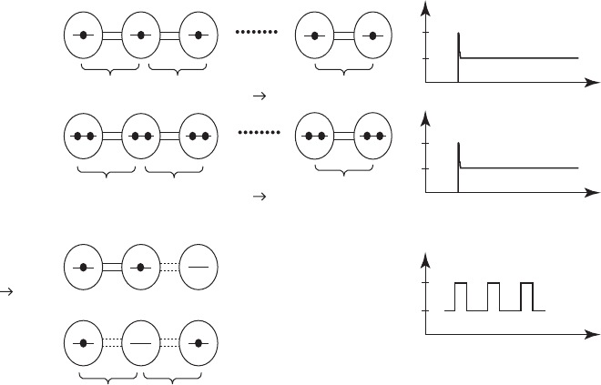
This schematic representation of the enhanced coupling shown in Figure 12.17 is based
on the coupling of two Si QDs, with an electron in one and a neighbouring QD. The top shows
singly occupied individual QDs, the middle shows doubly occupied QDs, and the bottom shows
exchanging occupations leading to oscillations. However, the exchange should be very fast. Only
when a trap replaces a regular QD, serving as an imposter with very slow emission and capture
rates, does telegraph-like slow oscillation occur. If triply occupied, g 4, 8, 12. It is more com-
plicated for the coupling of three. Nevertheless, using the chemical approach to the formation
of molecules, it is clear that coupling dictates occupation of states by electrons leading to initial
coupling.
g
g 2
g 4
g 2
g 4
g 1
g 4
g 2 g 2
4
2
0
g
8
4
0
g
2
1
0
G–V
V
1
V
2
V
a
V
1
V
a
increasing
singly occupied
V
a
increasing
doubly occupied
ν
ν
V
a
fixed
possible Coulomb
blockade
Not
coupled
Not
coupled
Coupled
Not
coupled
Spreading
Spreading
Time
Figure 12.17 A model for the enhanced coupling between QDs with an electron in one and in a neighbouring
QD. The top shows singly occupied individual QDs, the middle shows doubly occupied QDs, and the bottom shows
exchanging occupations leading to oscillations. However, the exchange should be very fast. When a trap replaces a
regular QD, serving as an imposter with very slow emission and capture rates, telegraph-like slow oscillation occurs.
If triply occupied, g 4, 8, 12.
CH012-I046325.indd 384CH012-I046325.indd 384 6/24/2008 3:37:23 PM6/24/2008 3:37:23 PM
Slow Oscillation and Random Fluctuation in Quantum Dots: Can we Overcome? 385
12.5 Conventional optical study of QDs
Before we deal with the study of instabilities in the photo-luminescence of QDs, we shall present
the management of absorption and luminescence collected from a distribution of QDs with con-
ventional spectroscopic techniques, i.e. measurement involves many QDs having a distribution of
sizes. Recently, Liu et al. [27] , undertook placing CdSe QDs, 2.4 nm, in a photonic crystal con-
sisting of silica spheres with a diameter of 300 nm. The purpose is to match the photo-emission
to the forbidden gap of the photonic crystal for enhanced interaction. In one dimension, interac-
tion is enhanced by placing optically active transitions within the resonance of a Fabry–Perrot
interferometer.
The CdSe/ZnS core-shell QDs with 2.4 nm size were commercially available from Evident
Technologies Inc . To study the thiolation effect on the PL properties of QDs, several substrate sur-
faces, e.g. Si substrate, Au fi lm on Si, and fused silica, with and without sulphur were introduced,
and the root-mean-square (RMS) surface roughness of these samples was measured by a Veeco
Dimension 3100 atomic force microscope (AFM). Substrates were fi rst immersed in a solution of
5 mM (3-mercaptopropyl)-trimethoxysilane (MPTMS) in ethanol for 24 h, followed by a thiola-
tion process for introducing sulphur onto a substrate surface. To study the interaction among the
QDs themselves, low to high concentrations of QDs in toluene solution were used to deposit the
thin fi lm with QDs onto the above substrates via evaporation of the toluene solvent. 3D photonic
crystals of silica spheres were self-assembled onto the substrate via evaporation of the ethanol,
and the fi lm thickness of more than 15 layers was obtained. Thermal treatment was used to sta-
bilize the stop-band of the photonic crystals, involving annealing for 3 h in a quartz tube in the
range of 300 1000°C. A Cary 300 Bio UV-Visible spectrophotometer was used for the meas-
urements of the transmission spectrum at normal incidence. At this point one must recognize
that the experimental technique used for this study is no different from 50 years ago, except AFM
was used to characterize the structure and surface roughness.
To study the interaction between QDs and between QDs and the matrix, we start from a simple
but fundamental scheme. There are two types of shifts of the emission peak, a one-way shift, for
example caused by pressure, temperature, etc., and a two-way shift, one up-shift of the higher
peak and another down-shift of the lower peak caused by coupling. Let the electron wavefunc-
tions
1
and
2
represent two uncoupled states, with
H
E
o
11
1
and
HE
o
22
2
.
In
HEΨΨ
,
HH H
o
1
, where H
1
represents interaction. Defi ning a coupling term,
CH 1
1
2
and
CH
21
1
. The wavefunction Ψ can be expressed by a linear combina-
tion of the two uncoupled states,
Ψ ab12
, where a and b are two constants. The secular
determinant ( E E
1
)( E E
2
) C
2
0. The roots give the two shifted energy states:
E
EE EE
C
12 12
2
2
22
⎛
⎝
⎜
⎜
⎜
⎞
⎠
⎟
⎟
⎟
⎟
.
(12.5)
For two identical QDs, E
1
E
2
, so that E
E
1
C, and E
E
1
– C. Since electrons at the
upper state can relax to the lower state via phonons, the observed transition is from the lower
state to the ground states, assumed not coupled. In this process, the observed PL is red shifted
as observed. For QDs coupled to a matrix such as some sort of molecular surface complex, the
observed shift may go up or down depending on whether the interaction molecules are located
at lower energy or high energy, respectively. For convenience to the reader, we point out that
interaction with the matrix indicated that the molecule in question is located at a lower energy
because the PL is blue shifted. Before we show the measured shifts, let us point out the prob-
lem when a distribution of particle size is present. For two adjacent QDs with different sizes, the
full expression represented by Eq. 12.5 should be involved. Not only are the uncoupled spectra
broadened by distribution, the interaction, as shown in Eq. 12.5, has additional spreading. The
particle size distribution resulted in a PL linewidth being much more than the intrinsic thermal
broadening. Therefore the measured data we obtained do not land themselves to simple model-
ling; nevertheless, from an application point of view, what really matters is what we measured.
Furthermore, we did not know the details of compacting the QDs with dilution followed by sub-
sequent removing of the toluene solvent. We estimated an increase in packing density of perhaps
CH012-I046325.indd 385CH012-I046325.indd 385 6/24/2008 3:37:23 PM6/24/2008 3:37:23 PM
386 Handbook of Self Assembled Semiconductor Nanostructures for Novel Devices in Photonics and Electronics
several per cent, from low to high concentration. With these uncertainties in mind, we present
the measured data as shown in Fig. 12.18 .
1.25 1.50 1.75
Photon energy (eV)
2.00 2.25 2.50 2.75 3.00
1.25
1.50
1.75
Photon energy (eV)
2.00
2.25
2.50 2.75 3.00
QDs on fused silica
QDs on unpacked spheres
QDs on packed spheres
Normalized PL intensity (a.u.)
PL intensity (a.u.)
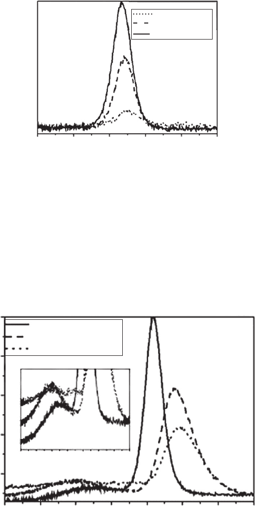
Figure 12.19 PL spectra of CdSe/ZnS QDs deposited on: (1) fused silica, (2) unpacked silica spheres, and (3)
packed crystals of silica spheres forming closed packed structures. Note that the main peak is now pushed up by the
molecular surface complex located below the main peak. The inset shows the portion of the surface peaks expanded.
1.8 2.0 2.2 2.4
Photon energy (eV)
2.6 2.8
PL intensity (a.u.)
Low concentration
Middle concentration
High concentration
Figure 12.18 PL spectra of CdSe/ZnS QDs deposited on an Si surface with native oxide for various dot
concentrations. The degree of stacking probably has increased by several percentage points. Note that there is a 1.3%
down-shift of the centre peak.
By correlating with AFM, we discovered that PL is much enhanced from surface roughness
resulting in enhanced surface interaction due to the increase of surface areas and effective sur-
face electric fi eld, which is very similar to the surface enhanced Raman. The roughness of the
fused silica is 20 times greater than that of the Si substrate with native oxide coverage, which
explains why we have an extra peak on the fused silica, but not on the Si wafer with thin and
smooth native oxide.
Figures 12.18 and 12.19 illustrate the acquisition of information regarding the coupling
between the quantum dots and between the quantum dots with surface complexes. Much of
CH012-I046325.indd 386CH012-I046325.indd 386 6/24/2008 3:37:23 PM6/24/2008 3:37:23 PM
Slow Oscillation and Random Fluctuation in Quantum Dots: Can we Overcome? 387
the understanding is derived from conventional spectroscopy. From the point of view of device
optimization, these conventional techniques may be adequate. However, the detailed interaction
must come from spectroscopy on a single quantum dot, which is presented in the next section.
12.6 Single quantum dot spectroscopy
As mentioned, only single QD, SQD, can display the correct linewidth. In addition to Fig. 12.1
showing the linewidth of InP on GaAs [6] being K
B
T , another excellent example is shown in
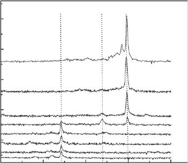
Fig. 12.20 of InAs QD from 1.7 ML on 100 nm of GaAs on semi-insulating GaAs(100), capped
by 100 nm of GaAs for protection. A cw Ar laser-pumped Ti–Sp laser between 700 and 900 nm
was used and focused to 2 μ m spot spatial resolution, and 0.15 meV of spectral resolution cor-
responding to 1.7 K. PL from 1.515 eV of GaAs shows LO-phonon replicas, allowing them to
account for varying diffusion: hitting an LO-phonon line allowing the creation of phonons lead-
ing to phonon-assisted carrier relaxation (see [25, 26] ). Without it, diffusivity would be much
lower. Varying diffusivity by selecting the excitation energy explains why PL at 1.447 eV in the
thin ( 1 nm) wetting layer is two orders of magnitude above the emission in the thick (200 nm)
GaAs. The two vertical dotted lines draw attention to oscillatory behaviour in P
IR
. In brief, SQD
spectroscopy allows far more detailed understanding, hitherto not possible with conventional
spectroscopy. Even if the QDs are oriented the same, symmetry and selection rules in optical tran-
sition cannot be accurately obtained without having SQD. For example, although most research-
ers assume the transition in QD with SS for ground state and PP for the fi rst excited state, as
shown in Fig. 12.4 , these atomic quantum numbers do not apply to any quantum dots, not even
for a sphere.
100
50
30
17
10
6.5
4.5
0
1.325 1.330 1.335
Energy (eV)
1.340 1.345
1000
2000
3000
4000
5000
PL intensity (CCD counts)
X X X
P
IR
, μW
Figure 12.20 Micro-PL of the single InAs QDs on GaAs, with dual-laser excitation at T 5 K with P
ex
2 0 n W,
varying P
IR
, ω
ex
1.503 eV , ω
IR
1.240 eV. For details, see [28, 29] .
12.7 Instability in the PL of quantum dots
Optical blinking, similar to “ telegraph instability ” discussed with respect to tunnelling, has been
observed in many small systems. The fi rst time I noticed blinking was in porous silicon, PS. Since
the period was in seconds, I dismissed it as totally uninteresting, useless and annoying conse-
quences of trapping. In fact I have even seen it with a broken silicon wafer by bending. Slow oscil-
lation in PL output has been reported in CdSe QDs [30] , in InP QD/GaInP SK QDs [31] . Figure
12.21 shows bi-level oscillation with a period 5 s [6] .
CH012-I046325.indd 387CH012-I046325.indd 387 6/24/2008 3:37:24 PM6/24/2008 3:37:24 PM
388 Handbook of Self Assembled Semiconductor Nanostructures for Novel Devices in Photonics and Electronics
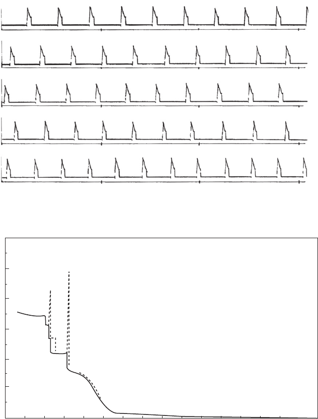
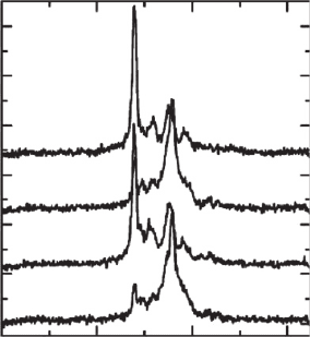
Figure 12.22 shows PL in InP QD on Ga
x
In
1
x
P involving switching with single, double and
even triple states. In the case of conductance switching how do processes with single, double,
etc states work? Let us go back to the top of Fig. 12.11 . Note that the difference of G involves
g 1, going from G 260 – 300 μ S, –340 μ S, –380 μ S, and fi nally –420 μ S, corresponding to
g 1, 2, 3, and 4. Note that even g 6 or 8 have been observed [26] . These higher values of g
correspond to coupling to even more dots with a given defect, or even more defects surrounding
a given dot. In Fig. 5 of [28] , it was pointed out that switching seems to be faster at higher tem-
perature. At least in the case of conductance switching, temperature seems to play a minor role.
In other words, phonons may not play a direct role in switching! Could that be due to some kind
of relaxation oscillation? In my book, I presented a summary of the thesis by my student Sen
[15] , solving the time-dependent Schrödinger equation. He found that the relaxation oscillation
dominates whenever the incident electron energy is not an eigen-state of the quantum system.
As I have mentioned, switching is present even in quantum wells. However, everything seems to
be magnifi ed in QDs. By the same token, switching is present in bulk; however, the overwhelming
DOS of the band states totally suppresses the effects of a few defects except in devices involving
oxide gates with charging and discharging [32] .
Figure 12.22 shows telegraph-like time dependence of PL from an InP/Ga
x
In
1
x
P single QD at
10 K. These nominally undoped QDs are separated, 1 0 μ m, having 5 nm high by 25 nm later-
ally determined by AFM. The area of illumination is 100 1 0 0 μ m
2
, with collection resolution
of 1.5 μ m and spectral resolution of 0.1 meV. I purposely detail the optical set-up to illustrate that
such a system is exactly what is needed to obtain detailed property on these QDs. For example,
this set-up can avoid the problem Ke Liu and I encountered during our study of the interaction
between QDs with a distribution of particle sizes. Note that the observed single-level and bi-level
switching are same as the cases in the conductance switching involving g 2, 4, 8, etc. The ideal
set-up is a combined capability of both single QD optical and electrical characterization, capa-
ble of measurements in situ to avoid contamination and the oxidation problem. In some sense, it
should be easier for QDs because we know where to look. Imagine looking for detailed features of
fi nding the trap of perhaps less than 1 nm in a conventional MOSFET with a dimension tens or
hundreds of nm.
In tunnelling via QW, the conservation of the longitudinal energy and transverse momentum
means that the transverse energy grows with the longitudinal energy fi xed, resulting in constant
conductance. Quantum wells with longitudinal separation by tens or hundreds of lattice constants,
but coupling in the transverse direction, are same as in usual solids. Quantum dots, on the other hand,
1.62 1.64 1.66
Ener
g
y (eV)
1.68
20
40
60
80
100
120
140
PL intensity (arb. units)
t 21s
t 15s
t 10s
t 4s
Figure 12.21 Slow oscillation in time of a single QD at low excitation. Note that there are two opposing out-
of-phase oscillations, one at 1.649 eV (1.1 meV) and the other at 1.656 eV (FWHM 1.27 meV), at the same
period of oscillation 5 s. After Bertram [6] .
CH012-I046325.indd 388CH012-I046325.indd 388 6/24/2008 3:37:25 PM6/24/2008 3:37:25 PM