Lowe D. Networking For Dummies
Подождите немного. Документ загружается.

Book II
Chapter 1
Planning a Network
87
Drawing Diagrams
Drawing Diagrams
One of the most helpful techniques for creating a network plan is to draw a
picture of it. The diagram can be a detailed floor plan, showing the actual
location of each network component. This type of diagram is sometimes
called a physical map. If you prefer, the diagram can be a logical map, which
is more abstract and Picasso-like. Any time you change the network layout,
update the diagram. Also include a detailed description of the change, the
date that the change was made, and the reason for the change.
You can diagram very small networks on the back of a napkin, but if the net-
work has more than a few computers, you’ll want to use a drawing program
to help you create the diagram. One of the best programs for this purpose
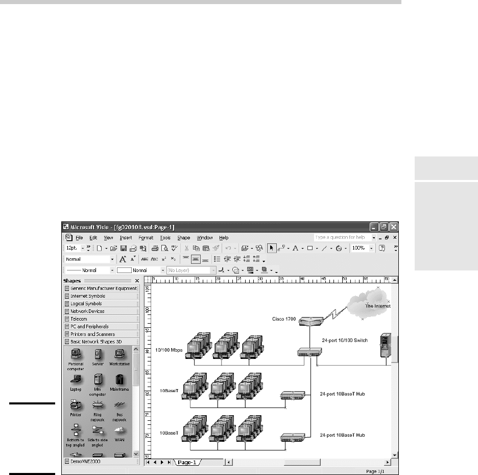
is Microsoft Visio, shown in Figure 1-6. Here’s a rundown of some of the fea-
tures that make Visio so useful:
Figure 1-6:
Using Visio
to draw a
network
diagram.
✦ Smart shapes and connectors maintain the connections you’ve drawn
between network components, even if you rearrange the layout of the
components on the page.
✦ Stencils provide dozens of useful shapes for common network
components — not just for client and server computers, but for rout-
ers, hubs, switches, and just about anything else you can imagine. If
10_625873-bk02ch01.indd 8710_625873-bk02ch01.indd 87 9/21/10 10:09 PM9/21/10 10:09 PM

88
Sample Network Plans
you’re really picky about the diagrams, you can even purchase stencil
sets that have accurate drawings of specific devices, such as Cisco
routers or IBM mainframe computers.
✦ You can add information to each computer or device in the diagram, such
as the serial number or physical location. Then, you can quickly print an
inventory that lists this information for each device in the diagram.
✦ You can easily create large diagrams that span multiple pages.
Sample Network Plans
In what’s left of this chapter, I present some network plans that are drawn
from real-life situations. These examples illustrate many of the network
design issues I’ve covered so far in this chapter. The stories you’re about to
read are true. The names have been changed to protect the innocent.
Building a small network: California
Sport Surface, Inc.
California Sport Surface, Inc. (CSS) is a small company specializing in the
installation of outdoor sports surfaces, such as tennis courts, running tracks,
and football fields. CSS has an administrative staff of just four employees
who work out of a home office. The company currently has three computers:
✦ A brand-new Dell desktop computer running Windows 7 Basic, shared
by the president (Mark) and vice president (Julie) to prepare proposals
and marketing brochures, to handle correspondence, and to do other
miscellaneous chores. This computer has a built-in gigabit Ethernet net-
work port.
✦ An older Gateway computer running Windows XP Home Edition, used
by the bookkeeper (Erin), who uses QuickBooks to handle the com-
pany’s accounting needs. This computer has a built-in 10/100 Mbps
Ethernet port.
✦ A notebook that runs Windows Vista, used by the company’s chief engi-
neer (Daniel), who often takes it to job sites to help with engineering
needs. This computer has a built-in 10/100 Mbps Ethernet port.
The company owns just one printer, a moderately priced inkjet printer that’s
connected to Erin’s computer. The computers aren’t networked, so when-
ever Mark, Julie, or Daniel needs to print something, the file must be copied
to a flash drive and given to Erin, who then prints the document. The com-
puter shared by Mark and Julie is connected to the Internet via a residential
DSL connection.
10_625873-bk02ch01.indd 8810_625873-bk02ch01.indd 88 9/21/10 10:09 PM9/21/10 10:09 PM
Book II
Chapter 1
Planning a Network
89
Sample Network Plans
The company wants to install a network to support these three computers.
Here are the primary goals of the network:
✦ Provide shared access to the printer so that users don’t have to
exchange data on flash drives to print their documents.
✦ Provide shared access to the Internet connection so that users can
access the Internet from any of the computers.
✦ Allow for the addition of another desktop computer, which the company
expects to purchase within the next six months, and potentially another
notebook computer. (If business is good, the company hopes to hire
another engineer.)
✦ The network should be intuitive to the users and shouldn’t require
extensive upkeep.
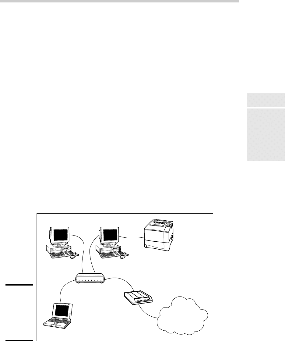
CSS’s networking needs can be met with the simple peer-to-peer network dia-
grammed in Figure 1-7. Here’s what the network requires:
✦ The network needs a combination DSL router and four-port gigabit
network switch. The company may outgrow this device when it adds a
laptop, but if and when that happens, another 4- or 8-port switch can be
added at that time.
✦ The firewall features of the DSL router will need to be enabled to protect
the network from Internet hackers.
✦ File and printer sharing will need to be activated on Erin’s computer,
and the printer will need to be shared.
Figure 1-7:
California
Sport
Surface’s
new peer-
to-peer
network.
Mark/Julie Erin
Printer
DSL router/
gigabit network switch
DSL modem
Daniel
The Internet
10_625873-bk02ch01.indd 8910_625873-bk02ch01.indd 89 9/21/10 10:09 PM9/21/10 10:09 PM

90
Sample Network Plans
Connecting two networks: Creative
Course Development, Inc.
Creative Course Development, Inc. (CCD) is a small educational publisher
located in central California that specializes in integrated math and sci-
ence curriculum for primary and secondary grades. It publishes a variety of
course materials, including textbooks, puzzle books, and CD-ROM software.
CCD leases two office buildings that are adjacent to each other, separated
only by a small courtyard. The creative staff, which consists of a dozen writ-
ers and educators, works in Building A. The sales, marketing, and adminis-
trative staff, which consists of six employees, works in Building B.
The creative staff (Building A) has a dozen relatively new personal comput-
ers, all running Windows Vista Business Edition, and a server computer
running Windows 2003 Server. These computers are networked via a single
24-port gigabit network switch. A fractional T1 line that’s connected to the
network through a small Cisco router provides Internet access.
The sales, marketing, and administrative staff (Building B) has a hodge-
podge of computers, some running Windows Vista but most running
Windows XP. They have a small Windows 2003 server that meets their
needs. The older computers have 10/100BaseT network interfaces; the
newer ones have gigabit interfaces. However, the computers are all con-
nected to a 10/100 Mbps Ethernet switch with 12 ports. Internet access is
provided by an ISDN connection.
Both groups are happy with their computers and networks. The problem
is that the networks can’t communicate with each other. For example, the
creative team in Building A prepares weekly product-development status
reports to share with the Administrative staff in Building B, and they fre-
quently go to the other building to look into important sales trends.
Although several solutions to this problem exist, the easiest is to bridge the
networks with a pair of wireless switches. To do this, CCD will purchase
two wireless access points. One will be plugged into the gigabit switch in
Building A, and the other will be plugged into the switch in Building B. After
the access points are configured, the two networks will function as a single
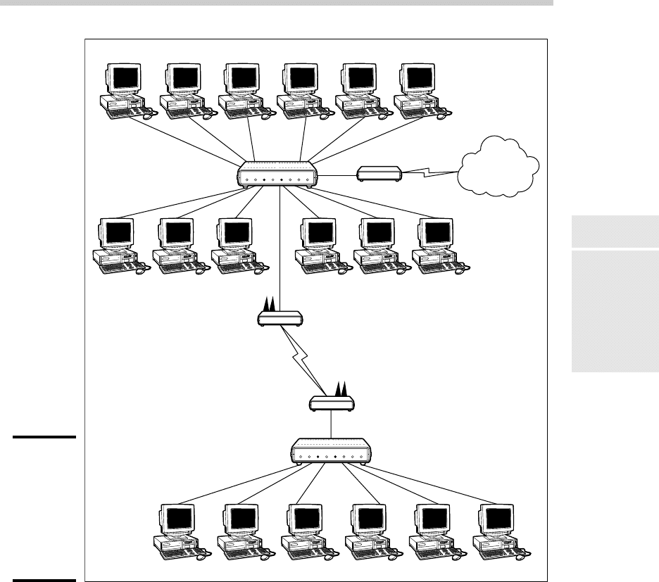
network. Figure 1-8 shows a logical diagram for the completed network.
Although the wireless solution to this problem sounds simple, a number of
complications still need to be dealt with. Specifically:
✦ Depending on the environment, the wireless access points may have
trouble establishing a link between the buildings. It may be necessary
to locate the devices on the roof. In that case, CCD will have to spend a
little extra money for weatherproof enclosures.
10_625873-bk02ch01.indd 9010_625873-bk02ch01.indd 90 9/21/10 10:09 PM9/21/10 10:09 PM
Book II
Chapter 1
Planning a Network
91
Sample Network Plans
Figure 1-8:
Creative
Course
Develop-
ment’s
wireless
network
solution.
Dave Y. Brenda M. Deborah Q. Julie D. Chris E. Alice M.
Emily D.
Sarah L. Toby S. Juan S. Richard O. Elias H.
The Internet
T1
Cisco 1700
24-port Gigabit Switch
Wireless Access Point
Wireless Access Point
12-port 10/100 Mbps Switch
Andrew T. Bill B. Shawna S. Maria L. Erin C. William H.
Building A
Building B
✦ Before the networks were connected, each network had its own DHCP
server to assign IP addresses to users as needed. Unfortunately, both
DHCP servers have the same local IP address (192.168.0.1). When the net-
works are combined, one of these DHCP servers will have to be disabled.
✦ In addition, both networks had their own Internet connections. With the
networks bridged, CCD can eliminate the ISDN connection altogether.
Users in both buildings can get their Internet access via the shared T1
connection.
10_625873-bk02ch01.indd 9110_625873-bk02ch01.indd 91 9/21/10 10:09 PM9/21/10 10:09 PM

92
Sample Network Plans
✦ The network administrator will also have to determine how to handle
directory services for the network. Previously, each network had its own
domain. With the networks bridged, CCD may opt to keep these domains
separate, or it may decide to merge them into a single domain. (Doing so
will require considerable work, so the company will probably leave the
domains separate.)
Improving network performance: DCH Accounting
DCH Accounting is an accounting firm that has grown in two years from
15 employees to 35, all located in one building. Here’s the lowdown on the
existing network:
✦ The network consists of 35 client computers and three servers running
Windows 2003 Server.
✦ The 35 client computers run a variety of Windows operating systems.
About a third (a total of 11) run Windows Vista Professional. The rest
run Windows XP Professional. None of the computers run Windows 7.
✦ The Windows Vista computers all have gigabit Ethernet cards. The older
computers have 10/100 Mbps cards.
✦ The server computers are somewhat older computers that have 10/100
Mbps network interfaces.
✦ All the offices in the building are wired with Category 5e wiring to a
central wiring closet, where a small equipment rack holds two 24-port
10/100 switches.
✦ Internet access is provided through a T1 connection with a Cisco 1700
router.
Lately, network performance has been noticeably slow, particularly
Internet access and large file transfers between client computers and the
servers. Users have started to complain that sometimes the network seems
to crawl.
The problem is most likely that the network has outgrown the old
10/100BaseT switches. All network traffic must flow through them, and
they’re limited to the speed of 100 Mbps. As a result, the new computers
with the gigabit Ethernet cards are connecting to the network at 100 Mbps.
The performance of this network can be dramatically improved in two steps.
The first step is to replace the 10/100 Mbps network interface cards in the
three servers with gigabit cards (or, better yet, replace the servers with
newer models). Second, add a 24-port gigabit switch to the equipment rack.
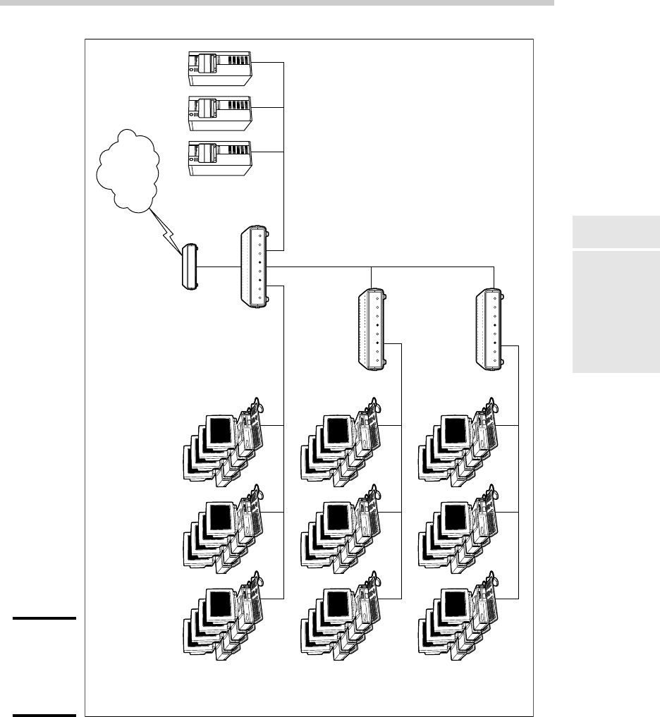
The equipment rack can be rewired, as shown in Figure 1-9.
10_625873-bk02ch01.indd 9210_625873-bk02ch01.indd 92 9/21/10 10:09 PM9/21/10 10:09 PM
Book II
Chapter 1
Planning a Network
93
Sample Network Plans
Figure 1-9:
DCH
Accounting’s
switched
network.
Gigabit
Cisco 1700
10/100 Mbps
10/100 Mbps
24-port 10/100 Switch
24-port 10/100 Switch
24-port Gigabit
Switch
Servers
The Internet
10_625873-bk02ch01.indd 9310_625873-bk02ch01.indd 93 9/21/10 10:09 PM9/21/10 10:09 PM

94
Sample Network Plans
1. Connect the servers, the Cisco router, and the gigabit clients to the
new gigabit switch. This will use 15 of the 24 ports.
2. Connect the two 10/100 switches to the new gigabit switch. This will
use two more ports, leaving 7 ports for future growth.
3. Divide the remaining clients between the two 10/100 switches. Each
switch will have 12 computers connected.
This arrangement connects all the gigabit clients to gigabit switch ports and
100 Mbps clients to 100 Mbps switch ports.
For even better performance, DCH can simply replace both switches with
24-port gigabit switches.
10_625873-bk02ch01.indd 9410_625873-bk02ch01.indd 94 9/21/10 10:09 PM9/21/10 10:09 PM

Chapter 2: Installing
Network Hardware
In This Chapter
✓ Installing network interface cards
✓ Installing network cable
✓ Attaching cable connectors
✓ Figuring out pinouts for twisted-pair cabling
✓ Building a crossover cable
✓ Installing switches
A
fter you have your network planned out, then comes the fun of actu-
ally putting everything together. In this chapter, I describe some of
the important details for installing network hardware, including cables,
switches, network interface cards, and professional touches, such as patch
panels.
Installing a Network Interface Card
To connect a computer to your network, the computer must have a network
interface. Virtually all computers sold in the last 10 years or so have a net-
work interface built-in on the motherboard. However, you may still encoun-
ter the occasional older computer that doesn’t have a built-in network
interface. In that case, you must install a network interface card to enable
the computer for your network. Installing a network interface card is a man-
ageable task, but you have to be willing to roll up your sleeves.
If you’ve installed one adapter card, you’ve installed them all. In other
words, installing a network interface card is just like installing a modem, a
new video controller card, a sound card, or any other type of card. If you’ve
ever installed one of these cards, you can probably install a network inter-
face card blindfolded.
Here’s a step-by-step procedure for installing a network interface card:
11_625873-bk02ch02.indd 9511_625873-bk02ch02.indd 95 9/21/10 10:09 PM9/21/10 10:09 PM
96
Installing a Network Interface Card
1. Gather up the network card and the driver disks. While you’re at it,
get your Windows installation CD just in case.
2. Shut down Windows and then turn off the computer and unplug it.
Never work in your computer’s insides with the power on or the power
cord plugged in!
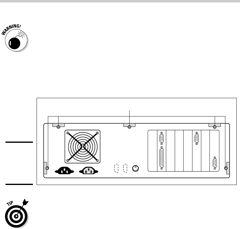
3. Remove the cover from your computer.
Figure 2-1 shows the screws that you must typically remove in order to
open the cover. Put the screws someplace where they won’t wander off.
Figure 2-1:
Removing
your
computer’s
cover.
Remove these screws
Note that if you have a name-brand computer such as a Dell or a
Compaq, opening the cover may be trickier than just removing a few
screws. You may need to consult the owner’s manual that came with the
computer to find out how to open the case.
4. Find an unused expansion slot inside the computer.
The expansion slots are lined up in a neat row near the back of the com-
puter; you can’t miss ’em. Any computer less than five years old should
have at least two or three slots known as PCI slots.
5. When you find a slot that doesn’t have a card in it, remove the metal
slot protector from the back of the computer’s chassis.
If a small retaining screw holds the slot protector in place, remove the
screw and keep it in a safe place. Then pull the slot protector out and
put the slot protector in a box with all your other old slot protectors.
(After a while, you collect a whole bunch of slot protectors. Keep them
as souvenirs or Christmas tree ornaments.)
6. Insert the network interface card into the slot.
11_625873-bk02ch02.indd 9611_625873-bk02ch02.indd 96 9/21/10 10:09 PM9/21/10 10:09 PM