Middleton W.M. (ed.) Reference Data for Engineers: Radio, Electronics, Computer and Communications
Подождите немного. Документ загружается.

28-32
REFERENCE
DATA
FOR
ENGINEERS
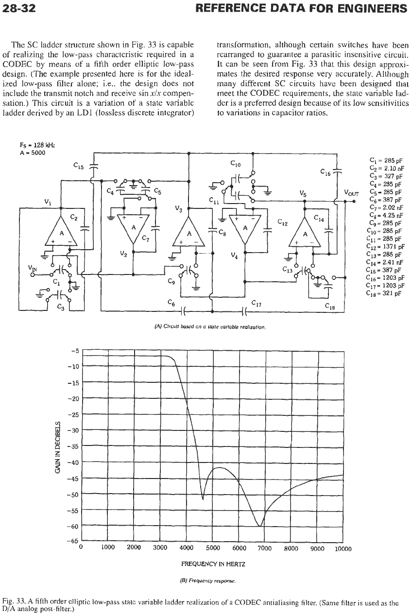
The SC ladder structure shown
in
Fig.
33
is capable
of
realizing the low-pass characteristic required in a
CODEC by means of a fifth order elliptic low-pass
design. (The example presented here
is
for the ideal-
ized low-pass filter alone; i.e., the design does not
include the transmit notch and receive sin
xix
compen-
sation.) This circuit is a variation of a state variable
ladder derived by an LD1 (lossless discrete integrator)
transformation, although certain switches have been
rearranged to guarantee a parasitic insensitive circuit.
It can be seen from Fig.
33
that this design approxi-
mates the desired response very accurately. Although
many different SC circuits have been designed that
meet the CODEC requirements, the state variable lad-
der is a preferred design because of its low sensitivities
to variations in capacitor ratios.
C1= 285 pF
Cz
=
2.10
nF
cg
=
327 pF
Ca
=
285 pF
C5
=
285
pF
Cs
=
387 pF
C,
=
4.25
nF
C,
=
285 pF
C1,
=
285 pF
C11= 285 pF
Ciz= 1371 pF
C,,
=
285
pF
C15
=
387 pF
C,,
=
1203 pF
C17
=
1203 pF
C,,
=
321 pF
c7= 2.02
nF
C1,= 2.41
nF
(A)
Clrcult
based on a state variable reallzaflon
(El)
Frequency
response.
Fig.
33.
A
fifth order elliptic low-pass state variable ladder realization
of
a
CODEC
antialiasing filter.
(Same
filter is
used
as
the
D/A
analog post-filter.)
DISCRETE-TIME
SIGNAL
PROCESSING
28-33
Surface-Acoustic-Wave Filters
A
surface-acoustic-wave (SAW) filter consists of an
input transducer that generates a surface-acoustic-wave
replica of the signal, a polished piezoelectric substrate
that acts as the propagation path for the waves, and an
output transducer that converts
the
delayed acoustic
waves back
to
an electrical signal. The input and output
transducers each have an impulse response with a finite
duration, and the construction is such that
the
transducer
electrodes have a one-to-one correspondence with indi-
vidual cycles
in
the
impulse response. The impulse
response center frequency
is
set by electrode spacing,
and its envelope is set by the electrode length. The fre-
quency-dependent transfer function of each transducer
is
the
Fourier transform of its impulse response.
The
surface-acoustic-wave device connected between a volt-
age source and a low-impedance load operates
as
a filter
with
an
overall transfer function that is the product of
the input and output transducer frequency responses and
a delay proportional to the separation between the cen-
ters of the transducers.
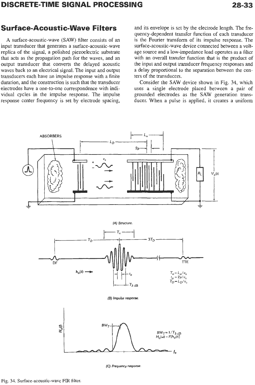
Consider the SAW device shown in Fig.
34,
which
uses a single electrode placed between a pair of
grounded electrodes as the SAW generation trans-
ducer. When a pulse is applied, it creates a uniform
(A)
Structure.
3TD
(5)
Impulse response.
(C)
Frequency response
Fig,
34.
Surface-acoustic-wave
FIR
filter.
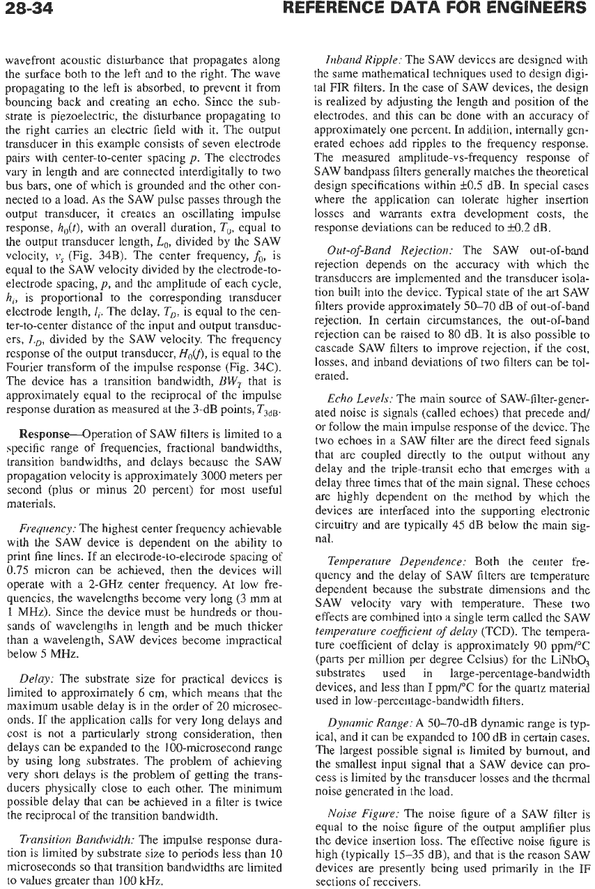
wavefront acoustic disturbance that propagates along
the surface both to the left and to the right. The wave
propagating to the left is absorbed, to prevent it from
bouncing back and creating an echo. Since the sub-
strate is piezoelectric, the disturbance propagating to
the right carries an electric field with it. The output
transducer in this example consists of seven electrode
pairs with center-to-center spacing
p.
The electrodes
vary in length and are connected interdigitally to two
bus bars, one of which is grounded and the other con-
nected
to
a load. As the SAW pulse passes through the
output transducer, it creates an oscillating impulse
response,
h,(t),
with an overall duration,
To,
equal to
the output transducer length,
Lo,
divided by the SAW
velocity,
v,
(Fig. 34B). The center frequency,
fo,
is
equal to the SAW velocity divided by the electrode-to-
electrode spacing,
p,
and the amplitude
of
each cycle,
hi,
is proportional to the corresponding transducer
electrode length,
1,.
The delay,
T,,
is equal to the cen-
ter-to-center distance of the input and output transduc-
ers,
Lo,
divided by the SAW velocity. The frequency
response of the output transducer,
Horn,
is equal to the
Fourier transform of the impulse response (Fig. 34C).
The device has a transition bandwidth,
BW,
that is
approximately equal to the reciprocal of the impulse
response duration as measured at the 3-dB points,
T3dB.
Response-Operation of SAW filters is limited to a
specific range of frequencies, fractional bandwidths,
transition bandwidths, and delays because the SAW
propagation velocity is approximately 3000 meters per
second (plus or minus
20
percent) for most useful
materials.
Frequency:
The highest center frequency achievable
with the SAW device is dependent on the ability to
print fine lines. If an electrode-to-electrode spacing of
0.75 micron can be achieved, then the devices will
operate with a 2-GHz center frequency. At low fre-
quencies, the wavelengths become very long
(3
nun
at
1
MHz).
Since the device must be hundreds or thou-
sands of wavelengths in length and be much thicker
than a wavelength, SAW devices become impractical
below 5 MHz.
Delay:
The substrate size for practical devices is
limited to approximately
6
cm, which means that the
maximum usable delay is in the order of
20
microsec-
onds. If the application calls for very long delays and
cost is not a particularly strong consideration, then
delays can be expanded to the 100-microsecond range
by using long substrates. The problem of achieving
very short delays is the problem of getting the trans-
ducers physically close
to
each other. The minimum
possible delay that can be achieved in a filter is twice
the reciprocal of the transition bandwidth.
Transition Bandwidth:
The impulse response dura-
tion is limited by substrate size to periods less than
10
microseconds
so
that transition bandwidths are limited
to values greater than 100 kHz.
Inband Ripple:
The SAW devices
are
designed with
the same mathematical techniques used to design digi-
tal FIR filters.
In
the case of SAW devices, the design
is realized by adjusting the length and position of the
electrodes, and this can be done with an accuracy of
approximately one percent.
In
addition, internally gen-
erated echoes add ripples to the frequency response.
The measured amplitude-vs-frequency response of
SAW bandpass filters generally matches the theoretical
design specifications within k0.5 dB.
In
special cases
where the application can tolerate higher insertion
losses and warrants extra development costs, the
response deviations can be reduced to
50.2
dB.
Out-of-Band Rejection:
The SAW out-of-band
rejection depends on the accuracy with which the
transducers
are
implemented and the transducer isola-
tion built into the device. Typical state of the
art
SAW
filters provide approximately
50-70
dB of out-of-band
rejection. In certain circumstances, the out-of-band
rejection can be raised
to
80
dB. It
is
also possible to
cascade SAW filters to improve rejection, if the cost,
losses, and inband deviations of two filters can be tol-
erated.
Echo Levels:
The main source
of
SAW-filter-gener-
ated noise is signals (called echoes) that precede and/
or follow the main impulse response of the device. The
two echoes in a SAW filter are the direct feed signals
that are coupled directly to the output without any
delay and the triple-transit echo that emerges with a
delay three times that of the main signal. These echoes
are highly dependent on the method by which the
devices are interfaced into the supporting electronic
circuitry and are typically 45 dB below the main sig-
nal.
Temperature Dependence:
Both the center fre-
quency and the delay of SAW filters
are
temperature
dependent because the substrate dimensions and the
SAW velocity vary with temperature. These two
effects
are
combined into a single term called the SAW
temperature coeflcient
of
delay
(TCD). The tempera-
ture coefficient
of
delay is approximately
90
ppm/”C
(parts per million per degree Celsius) for the LiNbO,
substrates used in large-percentage-bandwidth
devices, and less than
I
ppm/”C for the quartz material
used in low-percentage-bandwidth filters.
Dynamic Range:
A 50-70-dB dynamic range is typ-
ical, and it can be expanded to
100
dB in certain cases.
The largest possible signal
is
limited by burnout, and
the smallest input signal that a SAW device can pro-
cess is limited by the transducer losses and the thermal
noise generated in the load.
Noise Figure:
The noise figure of a SAW filter is
equal to the noise figure of the output amplifier plus
the device insertion loss. The effective noise figure is
high (typically 15-35 dB), and that
is
the reason SAW
devices
are
presently being used primarily in the
IF
sections of receivers.
28-35
SAW
Filters for
IS-95
Compatible CDMA Digital
Receivers*
Standing Acoustic Wave (SAW) filters are com-
monly used as band-pass filters at the intermediate fre-
quency in wideband superheterodyne receivers due to
their sharp magnitude characteristics and excellent lin-
ear phase response. These SAW filters are one of the
largest and most expensive components at the front
end
of
the receiver, making them less desirable for por-
table, consumer applications. Studies have shown that
minimum phase, finite impulse response SAW filters
(FIRS) can obtain similar performance with fewer tap
weights than their linear phase counterparts. They also
lead to the shortest possible propagation, or energy,
delays.
In
SAW filters a minimum phase design has an
additional advantage that the magnitude response is
less sensitive to errors in the tap weights. Therefore the
potential exists for reducing overall size and cost by
selecting a minimum phase design. However, the
phase response of a minimum phase FIR filter is non-
linear and does not meet linear phase constraints
required by IS-95 CDMA specifications. This phase
non-linearity can be controlled by using an adaptive
all-pass phase equalizer that maintains overall phase
linearity when the center frequency drifts due to envi-
ronmental temperature variations.
Minimum Requirements for
SAW
Performance
Commercially available transversal bandpass SAW
filters meet stringent stability requirements and are
widely used as the
IF
filter in superheterodyne digital
receivers. They are designed
to
have a very flat magni-
tude and linear-phase frequency response over the
bandpass region. Two commercially available SAW
filters which meet specifications for the IS-95-A
spread spectrum standard are the Thomson Microson-
ics FB E872 [32] and the SAWTEK 855292
[28].
In
the following discussion, the specifications of these
components, as summarized in Table
6,
are to repre-
sent those of a typical SAW filter.
TABLE
6.
MINIMUM
MAGNITUDE
RESPONSE
SPECIFICATTONS
-5
dB one-sided bandwidth
-33
dB
one-sided bandwidth
Amplitude ripple within
k
300
kHz
2
630
kHz
<
900
kHz
<
0.6 dB,
*
3”
rms
Phase linearity within
f
630
kHz
*
The
authors would like to acknowledge contributions
of
T.
Wilbom [36] to the section on “SAW Filters for
IS-95
Compatible CDMA Digital Receivers.”
Because the center frequency of a SAW filter
depends on the physical dimensions of the quartz sub-
strate, it drifts slightly over the operating temperature
range of -30 to 80°C. To compensate for this drift,
SAW filters are designed
to
have a two-sided
-5
dB
bandwidth greater than the minimum requirement of
2
.630
kHz
given
in
the table above. Thus, data signals
will pass through the filter even though the IF local
oscillator frequency does not exactly match the center
frequency fc of the SAW filter.
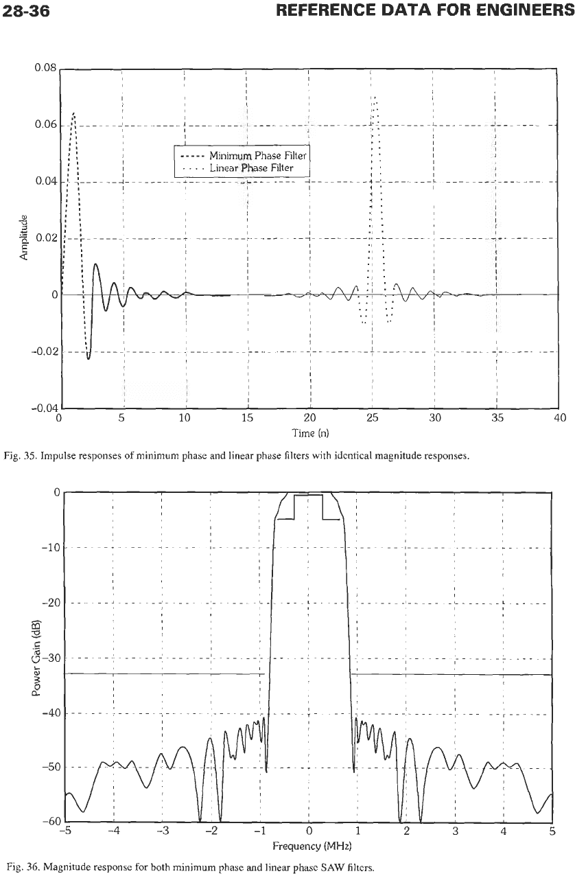
Fig. 35 illustrates the difference between the
impulse responses of two SAW filters with identical
magnitude responses, where one has a minimum
phase characteristic, and the other, linear phase. For
SAW filters, the minimum phase design has the addi-
tional advantage that the magnitude response is less
sensitive to errors in the tap weights. Therefore, the
potential exists for reducing the overall cost
of
the
SAW filter, as well as its size by using a minimum
phase SAW filter.
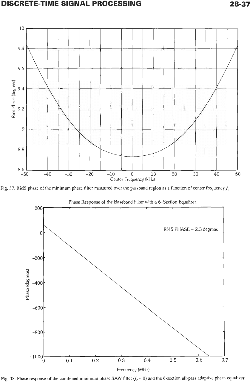
Fig. 36 shows the frequency response of a mini-
mum phase SAW filter which meets the magnitude
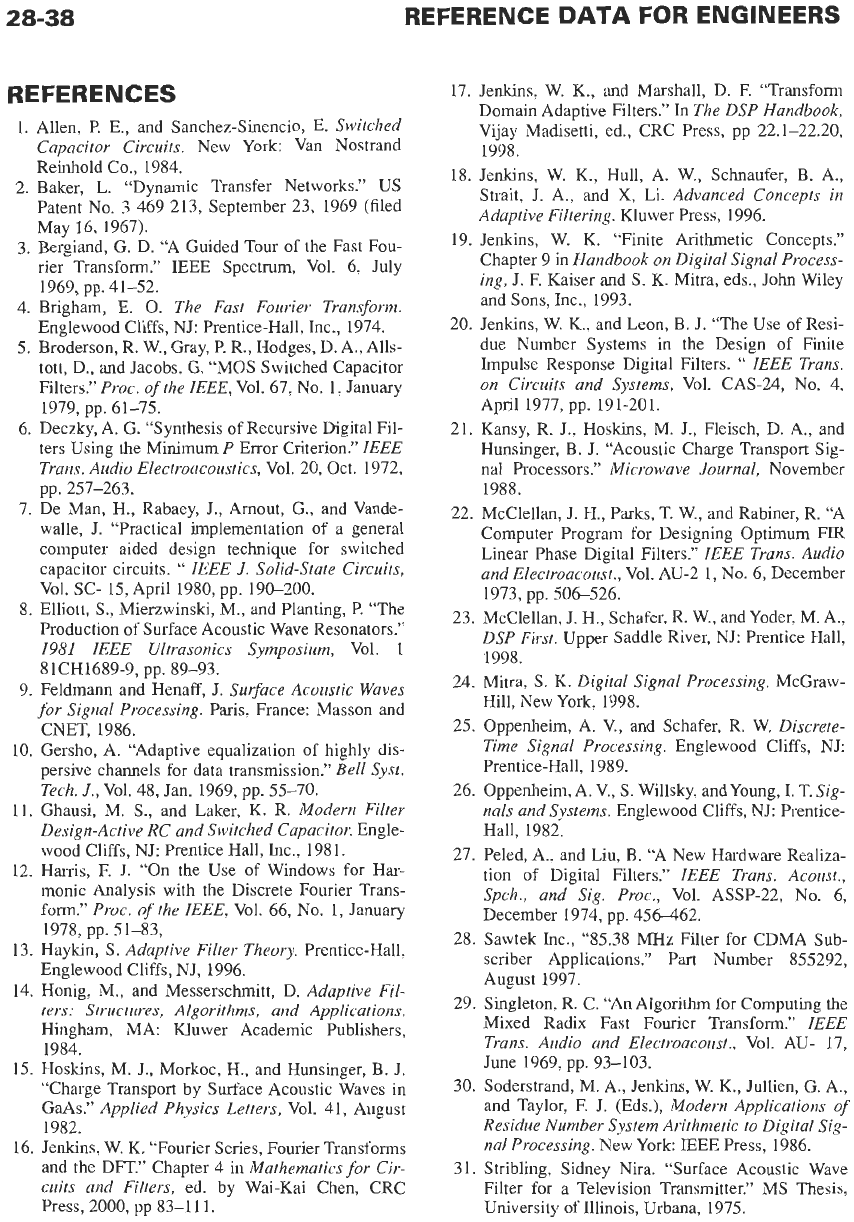
response specifications given in Table 6. But Fig.
37
illustrates that the rms phase is outside
of
those spec-
ifications, regardless of the center frequency
of
the
filter.
Note that the degree of phase nonlinearity changes
with respect to
f,.
Therefore, an equalizer that adjusts
with changes
inf,
is necessary
to
maintain the maxi-
mum SNR over variations in temperature.
An
IIR adaptive phase equalizer is capable of pro-
viding enough non-linear phase compensation to meet
the IS-95-A linear phase constraints. Examples pre-
sented in Reference 36 showed learning characteristics
of one-section IIR phase equalizers trained with both
the decision-directed algorithm (DDA) and the con-
stant modulus algorithm (CMA) adaptive phase equal-
izers, respectively. Both were able to minimize their
corresponding cost functions, achieving local minima
that brought the cascade combination of the minimum
phase SAW filter and the first order IIR adaptive equal-
izer into compliance with the magnitude and phase
specifications of Table 6. It was seen that the DDA
demonstrates considerably faster learning characteris-
tics than the CMA, providing the probability of error is
low and correct decisions are made most
of
the time.
The CMA learning characteristics showed a slower
learning (convergence) rate, and
a
large minimum
mean square error. Fig. 38 shows phase characteristic
of
the combined minimum phase
SAW
filter
(f,
=
0)
and the allpass IIR equalizing filter using six first order
all-pass IIR sections. The equalized minimum phase
filter has a slightly larger propagation delay than the
unequalized minimum phase SAW filter, but it
achieves a much smaller propagation delay than the
linear phase SAW filter at a greatly reduced cost. This
example demonstrates how analog and digital signal
processing technologies can be combined to achieve
efficient mixed mode solutions
to
certain practical
problems.
28-36
REFERENCE
DATA
FOR ENGINEERS
0.08
0.06
0.04
al
a
c
3
0.02
E
Q
0
-0.02
:.-
-- -- -
It
In
,I
7--
----
r-----
.-
I I
I I
I
I
I
I
I
-0.04
Time
(n)
Fig.
35.
Impulse responses of minimum phase and linear phase filters with identical magnitude responses.
0
-10
-2
0
73-
9
.E
9
-30
G
3
a
-40
-50
-60
.............................
-4
-3
-2
-1
0
1
2
3
4
5
Frequency
(MHz)
Fig.
36.
Magnitude response for both minimum phase and linear phase
SAW
filters.
DISCRETE-TIME SIGNAL PROCESSING
I I
\
0
0.1
0.2 0.3
0.4
0.5
0.6
-1ooc
28-37
I
0.7
L
40
-50
-
Center Frequency
(kHz)
Fig.
37.
RMS phase of the minimum phase filter measured over
the
passband region as
a
function of center frequency
f,
Phase Response
of
the Baseband Filter
with
a
6-Section Equalizer.
RMS
PHASE
=
2.3
degrees
\
3
1.
2.
3.
4.
5.
6.
7.
8.
17. Jenkins, W. K., and Marshall, D. F. “Transform
Domain Adaptive Filters.” In
The DSP Handbook,
Vijay Madisetti, ed., CRC Press, pp 22.1-22.20,
REFERENCES
Allen, P. E., and Sanchez-Sinencio, E.
Switched
Capacitor Circuits.
New York: Van Nostrand
1498
Reinhold Co., 1984.
Baker, L. “Dynamic Transfer Networks.”
US
Patent No. 3 469 213, September 23, 1969 (filed
May 16, 1967).
Bergiand, G. D. “A Guided Tour of the Fast Fou-
rier Transform.” IEEE Spectrum, Vol. 6, July
Brigham, E.
0.
The Fast Fourier Transform.
Englewood Cliffs, NJ: Prentice-Hall, Inc., 1974.
Broderson, R. W., Gray, P. R., Hodges, D. A., Alls-
tott, D., and Jacobs, G. “MOS Switched Capacitor
Filters.”
Proc. of the IEEE,
Vol. 67, No.
1,
January
Deczky, A. G. “Synthesis of Recursive Digital Fil-
ters Using the Minimum
P
Error Criterion.”
IEEE
Trans. Audio Electroacoustics,
Vol. 20, Oct. 1972,
De Man, H., Rabaey, J., Amout, G., and Vande-
walle, J. “Practical implementation of
a
general
computer aided design technique for switched
capacitor circuits.
“
IEEE
J.
Solid-state Circuits,
Elliott, S., Mierzwinski, M., and Planting, P. “The
Production of Surface Acoustic Wave Resonators.”
1981
IEEE Ultrasonics Symposium,
Vol. 1
1969, pp. 41-52.
1979, pp. 61-75.
pp. 257-263.
Vol. SC- 15, April 1980, pp. 190-200.
81CH1689-9, pp. 89-93.
9. Feldmann and Henaff,
J. Surface Acoustic Waves
for Signal Processing.
Paris, France: Masson and
CNET, 1986.
10. Gersho, A. “Adaptive equalization of highly dis-
persive channels for data transmission.”
Bell Syst.
Tech.
J.,
Vol. 48, Jan. 1969, pp. 55-70.
11. Ghausi, M. S., and Laker, K.
R.
Modern Filter
Design-Active RC and Switched Capacitor.
Engle-
wood Cliffs, NJ: Prentice Hall, Inc., 1981.
12. Harris,
E
J. “On the Use of Windows for Har-
monic Analysis with the Discrete Fourier Trans-
form.”
Proc. of the IEEE,
Vol. 66, No. 1, January
1978, pp. 51-83,
13. Haykin, S.
Adaptive Filter Theory.
Prentice-Hall,
Englewood Cliffs, NJ, 1996.
14. Honig, M., and Messerschmitt,
D. Adaptive Fil-
ters:
Structures, Algorithms, and Applications.
Hingham, MA: Kluwer Academic Publishers,
1984.
15. Hoskins, M. J., Morkoc, H., and Hunsinger, B.
J.
“Charge Transport by Surface Acoustic Waves in
GaAs.”
Applied Physics Letters,
Vol. 4
1,
August
1982.
16. Jenkins, W. K. “Fourier Series, Fourier Transforms
and the DFT.” Chapter 4 in
Mathematics for Cir-
cuits and Filters,
ed. by Wai-Kai Chen, CRC
Press, 2000, pp 83-111.
I,,”.
18. Jenkins, W. K., Hull, A. W., Schnaufer, B. A.,
Strait,
J.
A., and
X,
Li.
Advanced Concepts in
Adaptive Filtering.
Kluwer Press, 1996.
19. Jenkins, W. K. “Finite Arithmetic Concepts.”
Chapter 9 in
Handbook on Digital Signal Process-
ing,
J. F. Kaiser and S.
K.
Mitra, eds.,
John
Wiley
and
Sons, Inc., 1993.
20. Jenkins, W. K., and Leon, B. J. “The Use of Resi-
due Number Systems in the Design of Finite
Impulse Response Digital Filters.
“
IEEE Trans.
on Circuits and Systems,
Vol. CAS-24,
No.
4,
21. Kansy, R. J., Hoskins,
M.
J., Fleisch, D. A., and
Hunsinger, B. J. “Acoustic Charge Transport Sig-
nal Processors.”
Microwave Journal,
November
1988.
22. McClellan,
J.
H., Parks,
T.
W., and Rabiner, R. “A
Computer Program for Designing Optimum
FIR
Linear Phase Digital Filters.”
IEEE Trans. Audio
and Electroacoust.,
Vol.
AU-2
1, No. 6, December
1973, pp. 506-526.
23. McClellan,
J.
H., Schafer, R. W., andYoder, M. A.,
DSP First.
Upper Saddle River, NJ: Prentice Hall,
1998.
24. Mitra,
S.
K.
Digital Signal Processing.
McGraw-
Hill, New York, 1998.
25. Oppenheim, A.
V.,
and Schafer, R. W.
Discrete-
Time Signal Processing.
Englewood Cliffs, NJ:
Prentice-Hall, 1989.
26. Oppenheim, A. V., S. Willsky, and Young, I. T.
Sig-
nals and Systems.
Englewood Cliffs, NJ: Prentice-
Hall, 1982.
27. Peled, A., and Liu, B. “A New Hardware Realiza-
tion of Digital Filters.”
IEEE Trans. Acoust.,
Spch., and Sig. Proc.,
Vol.
ASSP-22,
No. 6,
December 1974, pp. 456-462.
28. Sawtek Inc., “85.38 MHz Filter for CDMA Sub-
scriber Applications.” Part Number 855292,
August 1997.
29.
Singleton,
R.
C.
“An Algorithm
for
Computing
the
Mixed Radix Fast Fourier Transform.”
IEEE
Trans. Audio and Electroacoust.,
Vol. AU- 17,
June 1969, pp. 93-103.
30.
Soderstrand,
M.
A., Jenkins, W.
K.,
Jullien, G. A,,
and Taylor, F. J. (Eds.),
Modern Applications of
Residue Number System Arithmetic to Digital
Sig-
nal Processing.
New York: IEEE Press, 1986.
31. Stribling, Sidney Nira. “Surface Acoustic Wave
Filter for
a
Television Transmitter.”
MS
Thesis,
University
of
Illinois, Urbana, 1975.
April 1977, pp. 191-201.
DISCRETE-TIME SIGNAL PROCESSING
28-39
32. Thomson Microsonics,
(FB
E872),
SAW Band-
pass Filter, Application: CDMA Mobile, Prelimi-
nary
Specifications, December 1998. 1985.
33. TIA/EIA/IS-95-A, Mobile Station-Base Station
Compatibility Standard for Dual-Mode Wideband
Spread Spectrum Cellular System. Arlington, VA:
Telecommunications Industry Association, 1995.
34. Trick, T.
N.,
and Jenkins, W.
K.
“Uncorrelated
Roundoff Noise
in
Digital Filters.”
In
Digital
Sig-
nal
Processing,
J.
K.
Agarwal, ed.
North
Holly-
wood, CA: Point Lobos Press, 1979.
35. Widrow,
B.,
and Steams,
S.
Adaptive
Signal
Pro-
cessing.
Englewood Cliffs, NJ: Prentice Hall, Inc.,
36. Wilborn,
T.
“Adaptive Allpass Phase Equalizer for
Digital Receivers: A Case Study,”
MS
Thesis,
Department
of
Electrical and Computer Engineer-
ing, University of Illinois, Urbana-Champaign,
1999.
29
Transmission Lines
Revised
by
Tatsuo
Itoh
Rule of Subscripts and Sign Conventions
Symbols
29-3
Fundamental Quantities and Line Parameters
Voltage and Current
29-5
Impedance and Admittance
29-6
Lines Open- or Short-circuited at the
Far
End
29-7
Voltage Reflection Coefficient and Standing-Wave Ratio
Power and Efficiency
29-10
Transformation
of
Impedance on Lines With High SWR
Mismatch and Transducer Loss
29-13
29-3
29-4
One End Mismatched
Generator and Load Mismatched
Notes on Equation
(3)
Examples
29-8
29-12
Attenuation and Resistance
of
Transmission Lines at Ultrahigh
Frequencies
29-15
Resonant Lines
29-15
Quarter-Wave Matching Sections
29-19
29-
I