Middleton W.M. (ed.) Reference Data for Engineers: Radio, Electronics, Computer and Communications
Подождите немного. Документ загружается.

29-2
REFERENCE
DATA
FOR ENGINEERS
Impedance Matching With Shorted Stub
29-19
Impedance Matching With Open Stub
29-19
Length
of
Transmission Line
29-21
Characteristic Impedance
of
Lines
29-21
Microstrip Lines
29-25
Quasi-TEM Characteristics
Attenuation
Frequency-Dependent Characteristics
Power-Handling Capacity
Strip Transmission Lines
29-27
Coplanar Transmission Lines
29-28
Attenuation and Power Rating
of
Lines and Cables
29-29
Attenuation
Power Rating
Army-Navy List
of
Preferred Radio-Frequency Cables
29-30
TRANSMISSION LINES
29-3
The equations and charts of this chapter
are
for
transmission lines operating in the TEM mode.
*
At the
beginning of several of the sections (e.g., “Fundamen-
tal Quantities and Line Parameters,” “Voltage and
Current,” “Impedance and Admittance,” “Voltage
Reflection Coefficient and Standing-Wave Ratio”) there
are accurate equations, according to conventional trans-
mission-line theory. These are applicable from the
lowest power and communication frequencies, includ-
ing direct current, up to the frequency where a higher
mode begins to appear on the line.
Following the accurate equations are others that
are
specially adapted for use in radio-frequency problems.
In cases
of
small attenuation, the terms
a2x2
and higher
powers in the expansion of expox, etc., are neglected.
Thus, when
m
=
(dPl8
=
0.1 neper (or about 1
decibel), the error in the approximate equations is of the
order
of
1
percent.
Much of the information is useful also in connection
with special lines that function in a quasi-TEM mode
(e.g., microstrip).
It should be observed that
Zo
and
Yo
are complex
quantities and the imaginary part cannot be neglected in
the accurate equations, unless preliminary examination
of the problems indicates the contrary. Even when
attenuation is small,
Zo
=
l/Yo
must often be taken at
its complex value, especially when the standing-wave
ratio is high. In the first few pages of equations, the
symbol
Ro
is used frequently. However, in later charts
and special applications, the conventional symbol
Zo
is
used where the context indicates that the quadrature
component need not be considered for the moment.
RULE
OF
SUBSCRIPTS AND
SIGN CONVENTIONS
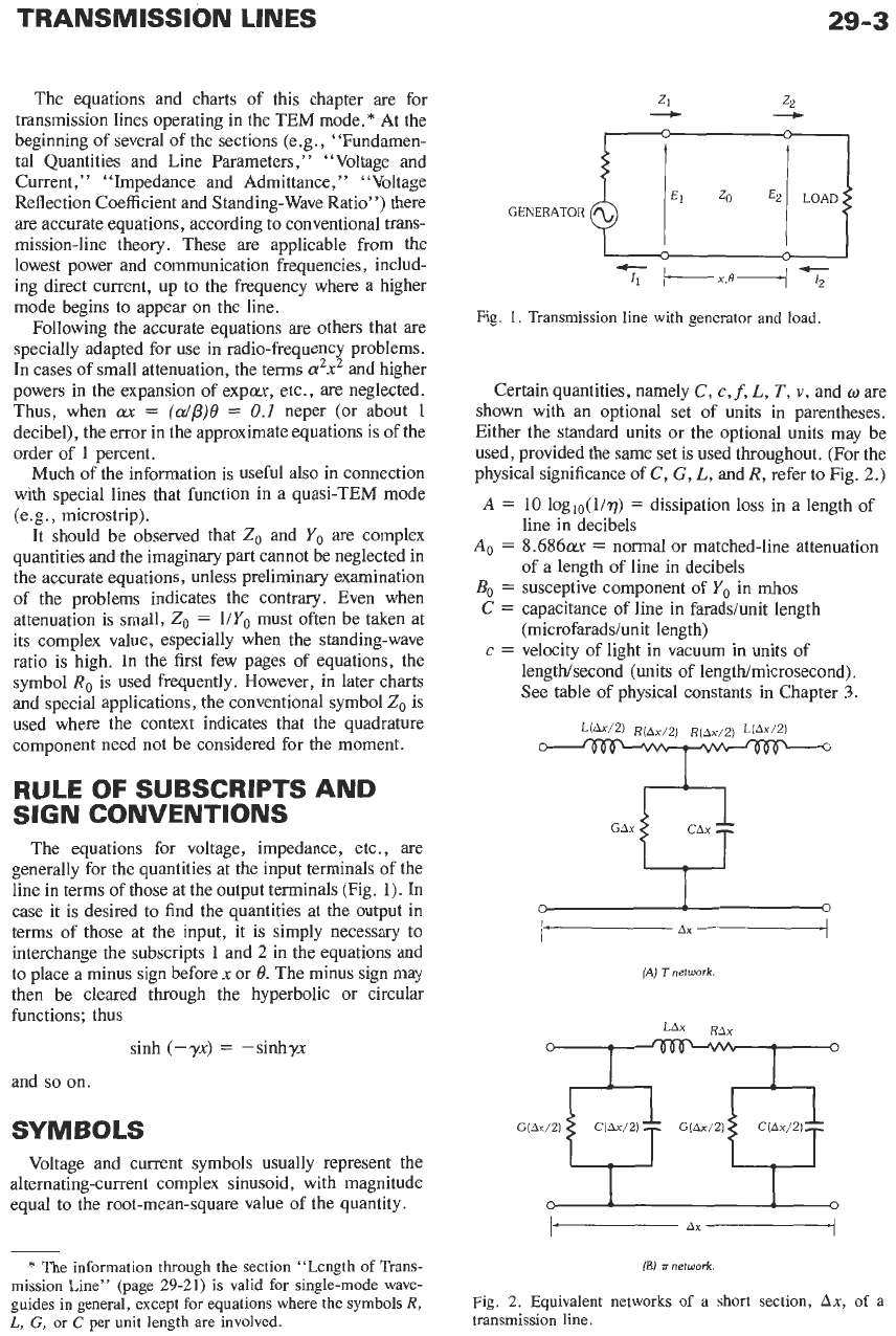
The equations for voltage, impedance, etc., are
generally for the quantities at the input terminals of the
line in terms of those at the output terminals (Fig. 1). In
case it is desired to find the quantities at the output in
terms of those at the input, it is simply necessary to
interchange the subscripts 1 and
2
in the equations and
to place a minus sign before
x
or
8.
The minus sign may
then be cleared through the hyperbolic or circular
functions; thus
sinh
(-yx)
=
-sinhyx
and
so
on.
SYMBOLS
Voltage and current symbols usually represent the
alternating-current complex sinusoid, with magnitude
equal to the root-mean-square value of the quantity.
-
/---x,o--/~
Fig.
1.
Transmission line with generator and load.
Certain quantities, namely
C,
c,
f,
L,
T,
v,
and ware
shown with an optional set of units in parentheses.
Either the standard units or the optional units may be
used, provided the same set is used throughout. (For the
physical significance
of
C,
G,
L,
andR, refer to Fig.
2.)
A
=
10 loglo(l/T)
=
dissipation loss in a length of
line in decibels
A0
=
8.686m
=
normal or matched-line attenuation
of a length of line in decibels
Bo
=
susceptive component of
Yo
in
mhos
C
=
capacitance of line in faraddunit length
c
=
velocity of light in vacuum in units
of
(microfaraddunit length)
lengthkecond (units of lengthhicrosecond).
See table of physical constants in Chapter
3.
GAx
0
(A)
7
network.
RAx
0
I
0
*
The information through the section “Length of Trans-
mission Line” (page
29-21)
is valid
for
single-mode wave-
guides in general, except for equations where the symbols
R,
L,
G,
or C per unit length are involved.
(E)
li
network
Fig.
2.
Equivalent networks
of
a short section,
Ax,
of
a
transmission line.
29-4
E=
fE
=
,E
=
IEtlatI
=
IEmaxl
=
IEminI
=
e=
Fp
=
G=
Go
=
ga
=
f=
gb
=
I=
fI
=
,I
=
i=
L=
P=
R=
Ro
=
r,
=
rb
=
S=
T=
v=
x,
=
voltage (root-mean-square complex
sinusoid) in volts
voltage
of
forward wave, traveling toward
load
voltage
of
reflected wave
root-mean-square voltage when
standing-wave ratio
=
1.0
root-mean-square voltage at crest of
standing wave
root-mean-square voltage at trough
of
standing wave
instantaneous voltage
G/wC
=
power factor of dielectric
frequency in hertz (megahertz)
conductance
of
line in mhoslunit length
conductive component of
Yo
in
mhos
Ya/Yo
=
normalized admittance at voltage
standing-wave maximum
Yb/Y,,
=
normalized admittance at voltage
standing-wave minimum
current (root-mean-square complex
sinusoid)
in
amperes
current of forward wave, traveling toward
load
current
of
reflected wave
instantaneous current
inductance of line in henrydunit length
(microhenrys/unit length)
power in watts
resistance of line in ohmdunit length
resistive component of
Zo
in
ohms
Za/Zo
=
normalized impedance at voltage
standing-wave maximum
ZblZo
=
normalized impedance at voltage
standing-wave minimum
I
EmaXIE,,,
I
=
voltage standing-wave ratio
delay of line in secondslunit length
(microseconds/unit length)
phase velocity of propagation in units
of
LengtWsecond (units of lengtldmicrosecond)
reactive component
of Zn
in ohms
x
=
distance between points
i
and
2
in units of
length (also used for normalized reactance
=
X/Z0)
Yl
=
GI
+
jB,
=
l/Zl
=
admittance in mhos
looking toward load from point 1
Yo
=
Go
+
jBo
=
l/Zo
=
characteristic
admittance of line in mhos
Z1
=
Rl
+
jX,
=
impedance in ohms looking
toward load from point
1
Zo
=
Ro
+
jXo
=
characteristic impedance
of
line in ohms
Z,,
=
input impedance
of
a line open-circuited at
the far end
Z,,
=
input impedance of a line short-circuited at
the far end
a
=
attenuation constant
=
neperdunit length
=
0.1151
X
decibeldunit length
p
=
phase constant in radiandunit length
y
=
a
+
jJ3
=
propagation constant
REFERENCE
DATA
FOR ENGINEERS
E
=
base of natural logarithms
=
2.718;
or
dielectric constant of medium (relative to air),
according to context
q
=
P2/Pl
=
efficiency (fractional)
8
=
px
=
electrical length or angle of line in
@
=
57.38
=
electrical angle of line in degrees
A
=
wavelength in units of length
A,
=
wavelength in free space
p
=
IpI
L
21j
=
voltage reflection coefficient
radians
plB
=
-20
logl0(l/p)
=
voltage reflection
coefficient in decibels
4
=
time phase angle of complex voltage at
voltage standing-wave maximum
Ij
=
half
the
angle of the reflection coefficient
=
electrical angle to nearest voltage
standing-wave maximum on the generator side
(radianslmicrosecond).
w
=
2qf
=
angular velocity in radiandsecond
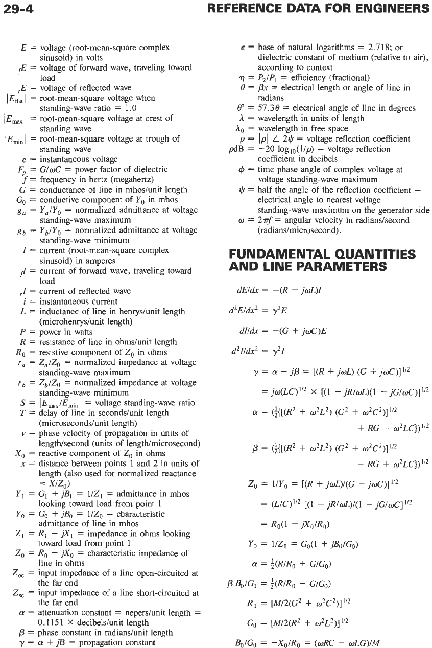
FUNDAMENTAL QUANTITIES
AND
LINE PARAMETERS
dE1dx
=
-(R
+
jwL)I
d2EldX2
=
y2E
dI/dX
=
-(G
+
jd)E
d21/dX2
=
y21
y
=
a
+
jp
=
[(R
+
jwL)
(G
+
~LX)]~‘~
=
~W(LC)I’~
x
[(l
-
jR/wL)(l
-
jG/oC)]”2
a
=
(g[(R2
+
w2L2)
(G2
+
wZG2)]l’*
+
RG
-
w~LC})”~
p
=
(g[(R2
+
02L2) (G2
+
w~C~)]~’~
-
RG
+
W~LC})”~
ZO
=
l/Yo
=
[(R
+
jwL)/(G
+
joC)]’/2
=
(L/C)”2
[(l
-
jRl~L)/(l
-
~GIOC]”~
=
Ro(1
+
jXo/Ro)
Yo
=
1/Zo
=
GO(l
+
jBoIG0)
=
+(R/R~
+
GIG,,)
p
B,IG,,
=
+(R/R~
-
G/G,)
Ro
=
[M12(G2
+
w2C2)]”2
GO
=
[M/2(R2
+
w2L2)]1i2
BoIGo
=
-Xo/Ro
=
(wRC
-
wLG)/M
TRANSMISSION LINES
29-5
where
=
Ro(l
+
jXo/Ro)
M
=
[(R2
+
w2L2) (G2
+
W~C~)]”~
+
RG
+
02LC
=
l/[Go(l
+
j
Bo/Go)l
=
(l/Go)
(1
-
jBo/Go)
1/T
=
v
=
fA
=
o/p
p
=
w/v
=
wT
=
2dA
R,
=
l/Go
=
(L/C)”’
yx
=
+
jpx
=
(dp)e
+
je
Bo/Go
=
-(Xo/Ro)
=
(R/2wL)
-
aFp
=
(dp)
-
Fp
e
=
px
=
2rx/h
=
2-x
Xo
=
-[R/~o(LC)”~]
+
(G/2oC)
(LK)”’
v
=
57.38
=
360x/h
=
360jzx
=
-(Rh/4~)
+
(iFp)Ro
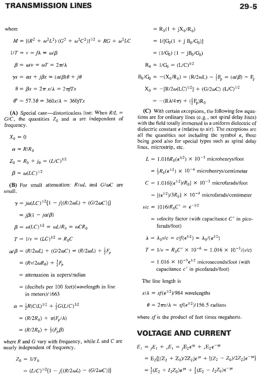
(A)
Special case-distortionless line: When R/L
=
G/~,
the quantities
Z,
and
a
are
independent
of
frequency.
(C)
With certain exceptions, the following few equa-
tions are for ordinary lines (e.g., not spiral delay lines)
with the field totally immersed in a uniform dielectric of
dielectric constant
E
(relative to air). The exceptions
are
all the quantities not including the symbol
E,
these
being good also for special types such as spiral delay
x,
=
0
(Y
R/Ro lines, microstrip, etc.
z0
=
R~
+
jo
=
(L/C)”~
L
=
1.016R0(~”’)
X
microhenryslfoot
p
=
w(LC)1’2
=
;RO(e1/’)
X
microhenryslcentimeter
C
=
1.016[(~’’~)/R~]
X
microfaradsifoot
(B)
For small attenuation: RIwL and G/wC
are
small.
=
[(E”*)/~R,]
X
microfarads/centimeter
y
=
jw(LC)
‘I2{
1
-
j[(R/20L)
+
(G/2wC)]}
v/c
=
1016/R0C’
=
E-~”
=
velocity factor (with capacitance
C’
in pico-
=jP(l
-WP)
/3
=
O(LC)”~
=
wL/R,
=
wCR0
T
=
l/v
=
(LC)’”
=
R
C
faraddfoot)
A
=
Aov/c
=
c/~(E”~)
=
A0/(~li2)
T
=
l/v
=
ROC’
X
0
a/p
=
(R12wL)
+
(G/2wC)
=
(R/2wL)
+
iFp
=
1.016
X
10-3/(v/c)
=
(Rv/2wRo)
+
iFp
=
attenuation in nepershadian
=
(decibels per 100 feet)(wavelength in line
=
1.016
X
10-3~1’2 microseconds/foot (with
capacitance
c’
in picofarads/foot)
The line length is
xlA
=
.xf(~’/~)/984 wavelengths
in meters)/ 1663
=
;R(C/L)~/~
+
;G(L/c)~/~
=
(R/2R0)
+
?r(F,/A)
=
(R/2R0)
+
i(F,p)
6
=
2m/A
=
.xf(~”~)/156.5 radians
where
.xf
is the product of feet times megahertz.
VOLTAGE
AND
CURRENT
where R and G vary with frequency, while L and
C
are
nearly independent of frequency.
El
=
fEl
+
,El
=
~EZEF
+
.E~E-~
zo
=
1/Y,
=
E2{[(Z2
+
Zo)/2Z2]ep
+
[(Z’
-
ZO)/~Z~]E-~}
=
$(E2
+
ZZZO)EY
+
$(E2
-
Z~ZO)E-~
=
(L/C)’/’{l
-
j[(R/20L)
-
(G/2wC)I}
29-6
REFERENCE DATA FOR ENGINEERS
=
E,[coshyx
+
(Z0/Z2) sinhyx]
=
E2 coshyx
+
IzZo sinhyx
=
[E2/(1
+
PZ)I(E”
+
P2E-P)
I,
=
fI,
+
,I1
=
f12E”
+
J2E-v
=
Yo(fE2~”
-
,E~E-”)
=
IZ{[(ZO
-
Z,)/2Zo]e”
+
[(ZO
+
Z2)/2Zo]€-”}
=
:(I2
+
EzYO)E”
+
$(I2
-
E~YO)E-”
=
12[coshyx
+
(Z2/Z0) sinhyx]
=
I,
coshyx
+
E2Yo sinhyx
=
112/(1
-
P2)I
(Ey”
-
P2E-F)
E,
=
AE2
+
BI,
I,
=
CE2
+
DI,
where the general circuit parameters are
A
=
coshyx,
B
=
Z, sinhyx,
C
=
Yo
sinhyx, and
D
=
coshyx.
Refer to section entitled “Matrix Algebra” in Chap-
ter
47.
(A)
When point 2 is at a voltage maximum or
minimum,
x’
is
measured from voltage maximum and
x’’ from voltage minimum (similarly for currents).
E,
=
E,,(coshyx‘
+
S-’
sinhyx’)
=
Emin(coshyx”
+
S
sinhyx“)
I,
=
I,,
(coshyx’
+
S-’
sinhyx’)
=
Imin(coshyx“
+
S
sinhyx”)
When attenuation is neglected
E,
=
E,,
(cos0’
+
j
S-‘
sine’)
=
Emin (cos$’’
+
j
S
sin$’‘)
(B)
Letting ZI
=
impedance of load, 1
=
distance
from load to point 2, and
xl
=
distance from load to
point
1
coshyxl
+
(Zo/Zl) sinhyx,
coshyl
+
(Zo/Zl) sinhyl
E,
=
E2
i,
=
1/2
IfI21
E“
x
sin[wt
+
27r(x/h)
-
$2
+
4
+
tan-’(Bo/Go)]
+
1/2
IJ,I
E-”
X
sin[wt
-
27r(x/h)
+
$2
+
4
+
tan-’(Bo/Go)]
(D)
For small attenuation
El
=
E2{[1
+
(Zo/Z2)cwc] cos0
+
j[(Zo/Z,)
+
ax] sine
I,
=
12{[1
+
(Z2/Zo)ax] cos0
+
j[(Z2/Zo)
+
cwc] sine}
(E)
When attenuation is neglected
E,
=
E,
cos0
+
j12Zo sin0
=
E2[cos0
+
j(Y2/Yo) sin01
=
fE2de
+
,E2~-jB
I,
=
1,
cos0
+
jE,Yo sin0
=
12[cos0
+
j(Zz/Zo) sin01
=
Yo(fE2de
-
,E2e-je)
General circuit parameters are
A
=
cos0
B
=
jZ, sin0
C
=
jYo
sin0
D
=
cos0
IMPEDANCE AND
ADMITTANCE
3=
Z2 coshyx
+
Zo sinhyx
ZO
20
coshyx
+
Z2 sinhyx
-
Yl
=
Y,
coshyx
+
Yo
sinhyx
YO
Yo
coshyx
+
Y2
sinhyx
(A)
The input impedance
of
a line at a position of
maximum or minimum voltage has the same phase
angle as the characteristic impedance.
Z,/zO
=
zb/zO
=
YO/Yb
=
rb
+
jo
=
s-’
coshyxl
+
(Z,/Zo) sinhyxl
coshyl
+
(Z,/Zo) sinhyl
+
fi
[Ez/
E-“
sin[wt
-
27r(x/h)
+
G2
I,
=
I,
at a voltage minimum (current maximum).
(C)
el
=
1/2
I
E21
E”
sinwt
+
27r(x/h)
-
G2
+
41
Y,/Y,
=
Y,/Yo
=
Zo/Z,
=
g,
+
j0
=
S-l
+
41
at a voltage maximum (current minimum).
TRANSMISSION LINES
29-7
(B)
When attenuation is small
Z,
-
[(Z,/Zo)
+
0x1
+
j[l
+
(Z2/Zo)cwcl
tan0
z,
[l
+
(Z,/Zo)cwcl
+
j[(Z,/ZO)
+
cwcl
tan0
-_
For admittances, replace
Zo
,
Z1
,
and
2,
by
Yo,
Y
,
and
Y,,
respectively.
(C)
When attenuation is neglected
Z,/ZO
+
j
tan0
-
1
-
j(Z2/Zo)
cote
-
Zl
-
--
Zo
1
+
j(Z2/Zo)
tan6
Z,/ZO
-
j
cot0
and similarly for admittances.
(D)
When attenuation
cwc
=
ea/@
is small and the
standing-wave ratio is large (say
>
1O)(Note:
The
complex value of
Zo
or
Yo
must be used in computing
the resistive component of
Zl
or
Y,
.):
For
8
measured
from a voltage minimum
Zl/Z,
=
[rb
+
(c~/p)e](i
+
tan20)
+
j
tan0
=
[rb
+
(dp)e](~~~~e)-~
+
j
tan8
(See Note 1)
Zo/Z1
=
Y,/Yo
=
[rb
+
(dp)e](i
+
de)
-
j
cote
=
[rb
+
(dp)~](sin~~)-~
-
j
cote
(See Note
2)
For
0
measured from a voltage maximum
zo/z,
=
Y,/Y~
=
[g,
+
(a/p)el(i
+
tan28)
+
j
tan0
(See Note
1)
Z1/Zo
=
[g,
+
(dp)q(l
+
cot20)
-
j
cote
(See Note
2)
Note
1:
Not valid when
0
=
n-12,
3d2,
etc., due
to approximation in denominator
1
+
(rb
+
ec~/p)~
tan2@
=
1
(or with
g,
in
place of
rb).
Note
2:
Not valid when
8
=
0,
n-,
2n-,
etc., due
to
approximation
in
denominator
1
+
(rb
+
eaip)2
Cot2e
=
1
(or with
g,
in place
of
rb).
For open- or
short-circuited line, valid at
0
=
0.
(E)
When
x
is
an
integral multiple
of
A12
or
h14:
For
x
=
nh/2,
or
0
=
nr
Zl
-
(Zz/Zo)
+
tanhnn-(a//P)
Zo
1
+
(Z2/Zo)
tanhnn-(a/p)
--
1
+
(Z2/Zo)
tanh(n
+
i).rr(a/p)
(Z2/Zo)
+
tanh(n
+
$.rr(a/p)
Zl
-
--
zo
(F)
For small attenuation, with any standing-wave
ratio: For
x
=
nM2,
or
0
=
nn-,
where
n
is an integer
Zl
-
(ZdZO)
+
n.rr(dP)
ZO
1
+
(z~/Zo)nn-(dP)
--
For
x
=
(n
+
;)A/2,
or
f3
=
(n
+
i)n-,
where
n
is an
integer or zero
1
+
(Z,/Zo)
(n
+
i)a(A/2)
(ZZ/Zo)
+
(n
+
i)a(h/2)
z1
-
-_
zo
1
+
s,z(n
+
f)
(dP)n-
ga2
+
(n
+
i)
(ff/P)n-
gbl
=
=
s,
Subscript
a
refers to the voltage-maximum point and
b
to the voltage minimum.
In
the above equations,
subscripts
a
and
b
may be interchanged, and/or
r
may be
substituted in place
of
g,
except for the relationships to
standing-wave ratio.
LINES OPEN- OR SHORT-
CIRCUITED AT
THE
FAR END
Point
2
is the open- or short-circuited end
of
the line,
from which
x
and
0
are measured.
(A)
Voltages and Currents: Use the equations of the
“Voltage and Current” section, with the following
conditions.
Open circuited line:
p2
=
1.00
L
0”
=
1.00
,E2
=
fE,
=
E,/2
z,
=
00
Short-circuited line:
p*
=
1.00
L
180”
=
-1.00
rE2
=
-fE2
E2
=
0
,I,
=
fI,
=
12/2
z,
=
0
For
x
=
nh/2
+
h/4,
or
0
=
(n
+
;)n-
29-8
REFERENCE
DATA
FOR ENGINEERS
(€5)
Impedances and admittances:
Z,,
=
Zo
cothyx
Z,,
=
Zo
tanhyx
Yo,
=
Yo
tanhyx
Y,,
=
Yo
cothyx
(C)
For small attenuation: Use the equations for
large swr in
(D)
of
the preceding section, with the
following conditions.
Open-circuited line:
ga
=
0
Short-circuited line:
rb
=
0
(D)
When attenuation
is
neglected:
Z,,
=
-jRo
cot0
Z,,
=
jRo
tan0
Yo,
=
jGo
tan0
Y,,
=
-jGo
cot0
(E)
Relationships between
Z,,
and
Zsc:
(zoczsc)'i2
=
zo
*
(Zsc/ZOc)
=
tanh yx
f
(Zoc/Zsc)
=
coth yx
(F)
When attenuation is small (except for
0
=
nd2,
n
=
1,
2, 3,
. .
.)
*(Z
sc
z
0,
=
*(Yoc/Ysc)1/2
=
*j[-(~,,/~,,)1"~
X
-
~~~~,,~~,,
-
Gs,/d,,)I
where
Yo,
=
Go,
+
jwC,,
and
Y,,
=
G,,
+
jd,,.
The
+
sign is to be used before the radical when
C,,
is
positive, and the
-
sign when
C,,
is negative.
(G)
RIIXI
component of input impedance of low-
attenuation nonresonant line:
Short-circuited line (except when
0
=
rr/2, 3d2, etc.)
Rl/IX'I
=
Gl/lBII
=
/(cr/p)@(tane
+
cote)
+
(B~/G~)J
=
((a/j3)(20/sin20)
+
(Bo/Go)l
Open-circuited line (except when
0
rr,
27~,
etc.)
RlIIXlI
=
GI//Bll
=
I(a//p)e(tane
+
cote)
-
(B,/G~)I
=
I(dp)(20/sin20)
-
(Bo/Go)/
VOLTAGE REFLECTION
COEFFICIENT
AND
STANDING-WAVE RATIO
p
=
,E/fE
=
-J/+
=
(Z
-
Zo)/(Z
+
Zo)
=
(Yo
-
Y)/(Y,
+
Y)
=
jpI
L
2*
where
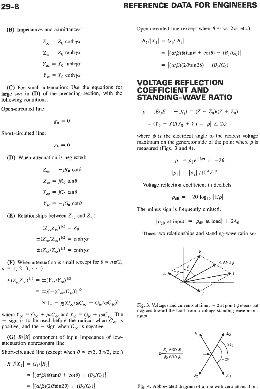
@
is
the electrical angle to the nearest voltage
maximum
on
the generator side of the point where
p
is
measured (Figs. 3 and
4).
p1
=
p2~-2nX
L
-20
lpll
=
lp*1
/10*o/'O
Voltage reflection coefficient
in
decibels
PdB
=
-20
loglo
I1/Pl
The minus sign is frequently omitted
/pdB
at input1
=
lpdB
at load1
+
2A0
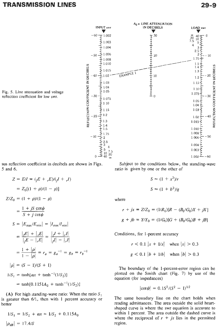
These two relationships and standing-wave ratio ver-
Fig.
3.
Voltages and currents at time
t
=
0
at point
IJI
electrical
degrees toward the load from a voltage standing-wave maxi-
mum.
JZ
Fig.
4.
Abbreviated diagram
of
a line with zero attenuation.
TRANSMISSION
LINES
5
40F
75
1;::
4
3
25-1
2-:
1
75-’-
15--
14--
1
3
/
1
15-1
1 10-1
1
05-1
1 04-1
1
03-r
1015-1
1 010-1
1
008
1
006
1 004-1
1
003-1
1
29-9
0
-1
--
-
10
Y
m
z
ti!
--
12-L-20
M
1075-L-30
g
8
0
Y
Q
c
z
-
U.
z
102-L-40
-
K
-1
-7
-50
00ZL-60
AD
=
LINE
ATTENUATION
INPUT
swr
IN
DECIBELS
v
i3’
1.003
1.004
Fig.
5.
Line
attenuation and voltage
reflection coefficient
for
low
swr.
1.15
1.3
1.4
1.5
1 75
2.5
sus
reflection coefficient in decibels are shown in Figs.
5
and 6.
Subject to the conditions below, the standing-wave
ratio is given by one or the other
of
s
=
(1
+
2)/r
s
=
(1
+
P)/g
where
r
+
jx
=
Z/Zo
=
(l/Ro)[R
-
(Bo/Go)X
+
jX]
g
+
jb
=
Y/Yo
=
(l/GO)[G
+
(Bo/Go)B
+
jB]
Conditions, for 1-percent accuracy
r
<
0.1
Ix
+
l/xl
g
<
0.1
Ib
+
l/bl
when
1x1
>
0.3
when
Ibl
>
0.3
IpI
=
(S
-
1)/(S
+
1)
US1
=
tanh[Lux
+
tmh-’(I/S2)J
=
tanh[0.1151Ao
+
tanh-’(l/S2)]
(A)
For high standing-wave ratio: When the ratio
Sl
is greater than 6/1, then with 1 percent accuracy or
better
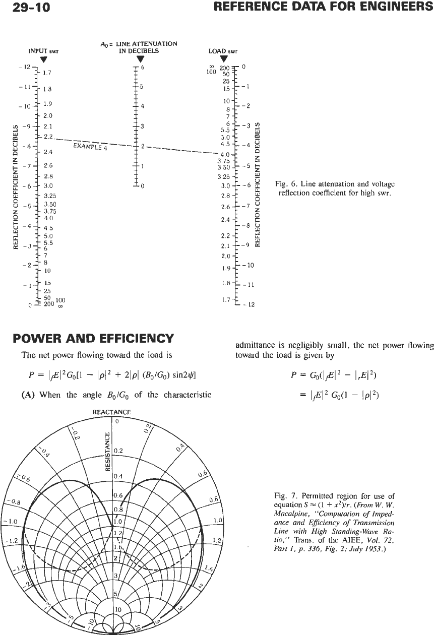
The boundary
of
the 1-percent-error region can be
plotted on the Smith chart
(Fig.
7)
by
use
of
the
equation (for impedances)
Icot+(
=
0.1S*/(S2
-
1)”2
The same boundary line on the chart holds when
reading admittances. The area outside the solid heart-
shaped curve is where the swr equation is accurate to
within
1
percent. The area outside the dashed curve is
where the reciprocal
of
r
+
jx
lies in the permitted
region.
29-10
REFERENCE
DATA
FOR
ENGINEERS
POWER
AND
EFFICIENCY
The net power flowing toward the load is
P
=
lfE12Go[l
-
IpI2
+
21pl
(&/Go)
sin2+]
(A)
When the angle
Bo/Go
of
the characteristic
Fig.
6.
Line attenuation and voltage
reflection coefficient for
high
swr.
::$3r
25
admittance is negligibly small, the net power flowing
toward the
load
is given by
P
=
GoCIfE12
-
IA2)
=
1fEI2
GO(1
-
IPI2)
Fig.
7.
Permitted region for
use
of
equations
-
(1
+
xZ)/r. (From
W. W.
Macalpine, “Computation
of
lmped-
ance and EfJiciency
of
Transmission
Line with High Standing-Wave Ra-
tio,”
Trans.
of
the
AIEE,
Vol.
72,
Part
1,
p.
336,
Fig.
2;
July
1953.)
TRANSMISSION
LINES
29-1
1
(C)
Efficiency, when swr is high:
=“(
GI
9
1
+
b?
where
R
is the ohmic resistance and
x
is the normalized
reactance, and similarly for
G
and
6.
It is important that
the
Rs
and
Gs
be computed properly, using equations in
the following section, headed ‘‘Transformation of Im-
pedance on Lines with High SWR.” Note the identity
of the efficiency equations with the left-hand terms of
the impedance equations. The conditions for accuracy
are the same as stated for the impedance equations for
high standing-wave ratio,
Example:
Physical significance of the equation for
efficiency at high standing-wave ratio: Subject to stated
conditions, approximately,
x
=
cot$ and
I
=
Imaxsin$.
The maximum error in the above expressions is
*
100(S2
-
1/S2)Bo/Go
percent
-+
4.34(S2
-
1/S2)B0/G0
decibels
When the ratio
SI
is greater than
6/1:
7
=
S1/S2
=
(1
-t
0.115A0S2)-1
When the load matches the line,
p2
=
0
and
the
efficiency is accurately
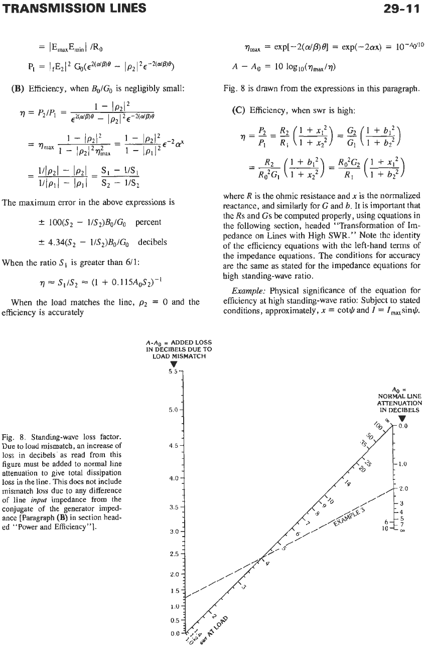
A-A0
=
ADDED LOSS
IN DECIBELS DUE TO
LOAD MISMATCH
v
A0
=
NORMAL LINE
ATTENUATION
IN DECIBELS
5.U
Fig.
8.
Standing-wave
loss
factor.
Due to load mismatch, an increase of
loss
in decibels‘as read from this
figure must be added to normal line
attenuation to give total dissipation
loss
in the line. This does not include
mismatch
loss
due to any difference
of
line
input
impedance from the
conjugate of the generator imped-
ance [Paragraph
(B)
in section head-
ed “Power and Efficiency”].
4.5
1