Middleton W.M. (ed.) Reference Data for Engineers: Radio, Electronics, Computer and Communications
Подождите немного. Документ загружается.

29-12
REFERENCE DATA FOR ENGINEERS
I,,
=
current standing-wave maximum, practically
constant along line when standing-wave ratio
>
6.
Then
P
=
Z2R
=
Zma2R/(l
+
x2)
When line length is greater than
3
wavelength, then
(D)
Loss
in nepers
=
1
log,(Pl/P2)
=
0.1151
X
For a matched line, loss
=
attenuation
=
(cr/p)O
=
Loss
in decibels
=
10
1oglo(Pl/P2)
=
8.686
X
(loss
When
2(dp)O
is small
(loss in decibels).
ax
nepers.
in nepers).
and
decibels/wavelength
(E)
For the same power flowing in a line with
standing waves as in a matched or “flat” line:
=
lEHat
I
2/R0
IEmaxI
=
IERatl
lErninI
=
lEHatl
lfEl
=
4
lERatl
(SI”
+
S-”’)
1
lrEl
=
$
\Enat/
(Si”
-
When the loss is small,
so
that
S
is nearly constant
over the entire length, then per half wavelength
(power loss)/(loss for flat line)
=
;(s
+
US)
(F)
The power dissipation per unit length, for unity
standing-wave ratio, is
AP~IAx
=
2cuP
(dissipation in watts/foot)
(line power in kilowatts)
=
2.30
(decibels/lOO feet)
where the decibelsllO0 feet is the normal attenuation for
a matched line.
When swr
>
1, the dissipation at a current maximum
is
S
times that for swr
=
1,
assuming the attenuation to
be due to conductor
loss
only. The multiplying factor
for local heating reaches a minimum value equal to
(S
+
l/S)/2
all along the line when conductor loss and
dielectric loss are equal.
(G)
Further considerations on power and efficiency
are given in the section headed “Mismatch and Trans-
ducer
Loss”
(p.
29-13).
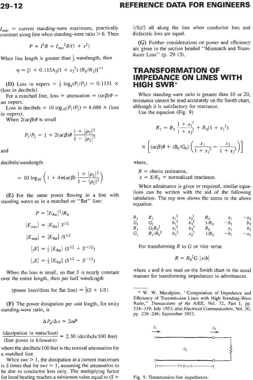
TRANSFORMATION OF
IMPEDANCE ON LINES
WITH
HIGH SWR”
When standing-wave ratio is greater than
10
or
20,
resistance cannot be read accurately on the Smith chart,
although it is satisfactory for reactance.
Use the equation (Fig.
9)
where,
R
=
ohmic resistance,
x
=
X/Ro
=
normalized reactance.
When admittance is given or required, similar equa-
tions can be written with the aid
of
the following
tabulation. The top row shows the terms in the above
equation.
For transforming
R
to
G
or
vice versa:
R
=
R2G
Ixlbl
where
x
and
b
are read on the Smith chart in the usual
manner for transforming impedances to admittances.
-
*
W.
W.
Macalpine, “Computation of Impedance and
Efficiency
of
Transmission Lines
with
High Standing-Wave
Ratio,”
Transactions
of
the
AIEE,
Vol.
72,
Part
I,
pp.
334-339;
July
1953;
also
Electrical
Communication,
Vol.
30,
pp.
238-246;
September
1953.
I
1-
B
=
2nx/h
--d
Fig.
9.
Transmission-line impedances.
TRANSMISSION LINES
29-13
The conditions for roughly 1-percent accuracy of the
equations are:
Standing-wave ratio is greater than 6/1 at input;
lBo/Go[
<
0.1;
r
+
jx or
g
+
jb (whichever is used, at
each end of line) meet the requirements stipulated in
paragraph
(A)
of the section headed “Voltage Reflec-
tion Coefficient and Standing-Wave Ratio” (p. 29-8);
and the line parameters and given impedance are known
to 1 -percent accuracy.
wavelength, then
R,
=
Rz[(l
+
xl’)/(l
+
x?)]
+
0.115AoRo(l
+
x12)
When line length is greater than
10,-
R2/Ro
+
(a/P)0
Ii
jR
1
+
xl’
1
+
x;
The equation for resistance transformation is derived
from expressions for high swr in paragraph
(A),
just
referred to.
Example:
A
load of 0.4
-
j2000
ohms
is fed through
a length of RG-218/U cable at a frequency of 2.0
megahertz. What are the input impedance and the
efficiency for a %-foot length of cable and for a
124-foot length?
For RG-218/U, the attenuation at 2.0 megahertz is
0.095 decibeVlO0 feet (see Fig. 29). The dielectric
constant
E
=
2.26, and
Fp
is negligibly small. Then, by
equations in
(B)
and
(C),
p. 29-5:
BoIC0
=
dP
=
(dB/100 ft) (h,,~ers)/1663
=
r0.095
X
150/(2.26)1’2]/1663
=
0.0057
x/h
=
$~“’/984
=
24
X
2.0
X
1.5/984
=
0.073
0
=
2rrxlh
=
0.46 radian for 24-foot length
while
x/h
=
0.38 and
8
=
2.4 for 124-foot length
Z,/Zo
=
(0.4
-
j2000)/50
=
0.008
-
j40
For the %-foot length, by the Smith chart
x1
=
X,/Zo
=
-1.9, or
XI
=
-95 ohms
The conditions for accuracy of the resistance trans-
formation
equation
are
satisfied.
Now
1
+
x12
=
1
+
(1.9)’
=
4.6
1
+
.a;
=
1
+
(40)’
=
1600
R,
=
0.4(4.6/1600)
+
50
X
4.6
X
0.0057
X
[0.46
-
(1.9/4.6)
+
(40/1600)]
=
0.0012
+
0.105
=
0.106 ohm
The efficiency equation in paragraph
(C)
on p. 29-1 1
gives
7
=
0.0012/0.106
=
0.0113, or 1.1 percent
where the 0.0012 figure is taken directly from the first
quantity
on
the right-hand side of the computation of
the value of
R
1.
Similarly, for the 124-foot length, xI
=
1.1,
XI
=
55
ohms, 1
+
x,’
=
2.21, Rl
=
0.00055
+
1.83
=
1.83
ohms
r]
=
0.00055/1.83
=
3.1
X
Tabulating the results,
or 0.03 percent
Input
Length Impedance Efficiency
Loss
(feet)
(ohms)
(%I
(dB)
24
0.106
-
j95 1.1
19.6
124
1.8
+j55
0.03
35
The considerably greater loss for 124 feet compared
with 24 feet is because the transmission passes through
a current maximum where the loss per unit length is
much higher than at a current minimum.
MISMATCH AND
TRANSDUCER
LOSS
Figs.
5,
6, and
8,
plus the equations in this section,
permit the calculation of loss when impedance mis-
match exists in a transmission-line system;
also,
the
change in standing-wave ratio along a line due to
attenuation can be determined.
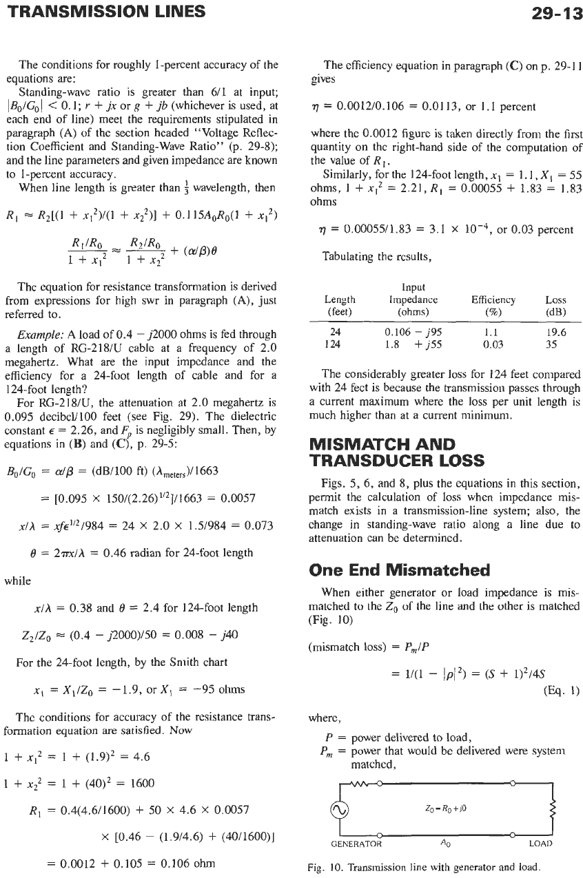
One End Mismatched
When either generator or load impedance
is
mis-
matched to the
Zo
of
the line and the other is matched
(Fig. 10)
(mismatch
loss)
=
P,/P
where,
P
=
power delivered to load,
P,
=
power that would be delivered were system
matched,
Q
Zo
=
Rg
+
j0
I
.-.
?.
I
GENERATOR
A0
LOAD
-
”
Fig.
10.
Transmission line
with
generator and load.
29-14
REFERENCE
DATA
FOR ENGINEERS
S
=
standing-wave ratio of mismatched impedance
Compared with an ideal transducer (ideal matching
referred to
Zo
.
network between generator and load)
(transducer loss)
=
A,
+
10 loglo(Pm/P) decibels
(Eq.
2)
where
A.
=
normal attenuation of line.
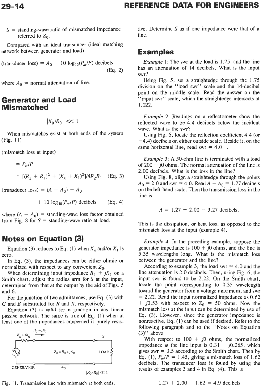
Generator and Load
Mismatched
IX,/R,l
<<
1
When mismatches exist at both ends of the system
(Fig.
11)
(mismatch
loss
at input)
=
Pm/P
=
[(R,
+
R1)’
+
(X,
+
X1)’]/4R,R,
(Eq.
3)
(transducer
loss)
=
(A
-
A,)
+
A0
+
10
logl,(Pm/P) decibels
(Eq. 4)
where
(A
-
A,)
=
standing-wave
loss
factor obtained
from Fig.
8
for
S
=
standing-wave ratio at load.
Notes on Equation
(3)
Equation
(3)
reduces to Eq.
(1)
when
X,
and/or
XI
is
zero.
In Eq.
(3),
the impedances can be either ohmic or
normalized with respect to any convenient
Zo
.
When determining input impedance
R1
+
jXl
on a
Smith chart, adjust the radius
arm
for
S
at the input,
determined from that at the output by the aid of Figs.
5
and
6.
For the junction of two admittances, use
Eq.
(3)
with
G
and
B
substituted for
R
and
X,
respectively.
Equation
(3)
is
valid for a junction
in
any linear
passive network. The same is true
of
Eq.
(1)
when at
least one of the impedances concerned is purely resis-
RI
+JX~
R,+&
+
9
Zo=Ro+,Xo
LoADr
I
-
GENERATOR
A0
IXo/RoI
<<
1
Fig.
11.
Transmission line with mismatch
at
both ends.
tive. Determine
S
as if one impedance were that of a
line.
Examples
Example
1:
The swr at the load is
1.75,
and the line
has an attenuation of 14 decibels. What is the input
swr?
Using Fig.
5,
set a straightedge through the
1.75
division on the “load swr” scale and the 14-decibel
point on the middle scale. Read the answer on the
“input swr” scale, which the straightedge intersects at
1.022.
Example
2:
Readings on a reflectometer show the
reflected wave to be 4.4 decibels below the incident
wave. What is the swr?
Using Fig.
6,
locate the reflection coefficient 4.4 (or
-4.4) decibels on either outside scale. Beside it, on the
same horizontal line, read swr
=
4.0+.
Example
3:
A 50-ohm line is terminated with a load
of
200
+
j0
ohms. The normal attenuation
of
the line is
2.00
decibels. What is the
loss
in the line?
Using Fig.
8,
align a straightedge through the points
A,
=
2.0
and swr
=
4.0. ReadA
-
A,
=
1.27
decibels
on the left-hand scale. Then the transmission
loss
in the
line is
A
=
1.27
+
2.00
=
3.27
decibels.
This is the dissipation, or heat
loss,
as opposed to the
mismatch
loss
at the input (example 4).
Example
4: In the preceding example, suppose the
generator impedance is 100
+
j0
ohms,
and the line is
5.35
wavelengths long. What is the mismatch
loss
between the generator and the line?
According to example
3,
the load swr
=
4.0 and the
line attenuation is
2.0
decibels. Then, using Fig.
6,
the
input swr is found to be
2.22.
On
the Smith chart,
locate the point corresponding to
0.35
wavelength
toward the generator from a voltage maximum, and swr
=
2.22.
Read the input normalized impedance as
0.62
+
j0.53
with respect to
Zo
=
50
ohms.
Now the
mismatch
loss
at the input can be determined by use
of
Eq.
(3).
However, since the generator impedance is
nonreactive, Eq.
(1)
can be used if desired. Refer to the
following paragraph and to the “Notes on Equation
(3)”
above.
With respect to 100
+
j0
ohms, the normalized
impedance at the line input is
0.31
+
j0.265,
which
gives swr
=
3.5
according to the Smith chart. Then by
Eq.
(l),
P,/P
=
1.45,
giving a mismatch
loss
of 1.62
decibels. The transducer
loss
is found by using the
results of examples
3
and 4 in
Eq.
(4). This is
1.27
+
2.00
+
1.62
=
4.9 decibels
TRANSMISSION LINES
29-15
ATTENUATION AND
RESISTANCE OF
TRANSMISSION LINES AT
ULTRAHIGH FREQUENCIES
The normal or matched-line attenuation in decibels/
100
feet is
AIOO
=
4.34R,/Z0
+
2.78f~"~F,
where the total line resistance/100 feet (for perfect
surface conditions of the conductors) is, for copper
coaxial line
R,
=
O.l(l/d
+
1/D)f112
and for copper 2-wire open line
R,
=
(0.2/d)f112
where,
D
=
diameter
of
inner surface of outer coaxial
d
=
diameter of conductors (coaxial-line center
f
=
frequency in megahertz,
E
=
dielectric constant relative to air,
conductor in inches,
conductor) in inches,
Fp
=
power factor of dielectric at frequency
f.
For other conductor materials, the resistance of a
conductor of diameter
d
(and similarly for D) is
O.l(l/d)
(fp,p/pCu)lI2
ohms/100 feet
where,
p,
=
relative permeability of material (1 for
nonmagnetic materials),
p
=
resistivity of material at any temperature,
pcu
=
resistivity of copper at 20
"C
(1.724
microhms-centimeter)
,
f
=
frequency in megahertz.
RESONANT LINES
Symbols:
fo
=
resonance frequency in megahertz
G,
=
conductance load in
mhos
at voltage
standing-wave maximum, equivalent to some
or all of the actual loads
k
=
coefficient of coupling
n
=
integral number
of
quarter wavelengths
p
=
k2QlsQ2s
=
load transfer coefficient or
P,
=
power converted into heat in resonator
P,
=
power available from generator in watts
matching factor
=
E0:/4R,,
P,
=
power transferred when load is directly
connected to generator (for single
resonators); or an analogous hypothetical
power (for two coupled resonators)
Q
=
figure of merit of a resonator as it exists,
whether loaded or unloaded
Qd
=
doubly loaded
Q
(all loads being included)
Q,
=
singly loaded
Q
(all loads included except
one). For a pair of coupled resonators,
Q,,
is the value for the first resonator when
isolated from the other. (Similarly for
QZs)
Q,
=
unloaded
Q
Rb
=
resistance load in ohms at voltage
standing-wave minimum, equivalent to some
or all of the actual loads
R,
=
resistance similar to
R,
except for unloaded
resonator
R,
=
generator resistance, referred to
short-circuited end
R,
=
load resistance
S,
=
Rl/R2
or
R,/R1
=
mismatch factor between
generator and load
pair of resonators
minimum point
Zlo
=
characteristic impedance of the first
of
a
O1
=
electric angle from a voltage standing-wave
(A)
Q
of a resonator (electrical, mechanical, or any
other) is
(energy stored)
(energy dissipated per cycle)
Q
=
25-
-
(energy stored)
-
2?rf
(power dissipation)
In a freely oscillating system, the amplitude decays
exponentially.
I
=
Io
exp
(-?rft/Q)
(B)
Unloaded
Q
of a resonant line:
Q,
=
P/2a
the line length being
n
quarter-wavelengths, where
n
is a
small integer. The losses in the line are equivalent to
those in a hypothetical resistor at the short-circuited end
(D)
in the section headed "Impedance and Admit-
tance")
R,
=
n5-Zo/4Q,
(C)
Loaded
Q
of a resonant line (Fig.
12):
Q-'
=
Q;'
f
(4Rb/nTZo)
f
(4Ga/1276'o)
=
(4/n.rrZ0) (R,
+
R,
+
G,/Y:)
29-16
REFERENCE
DATA
FOR
ENGINEERS
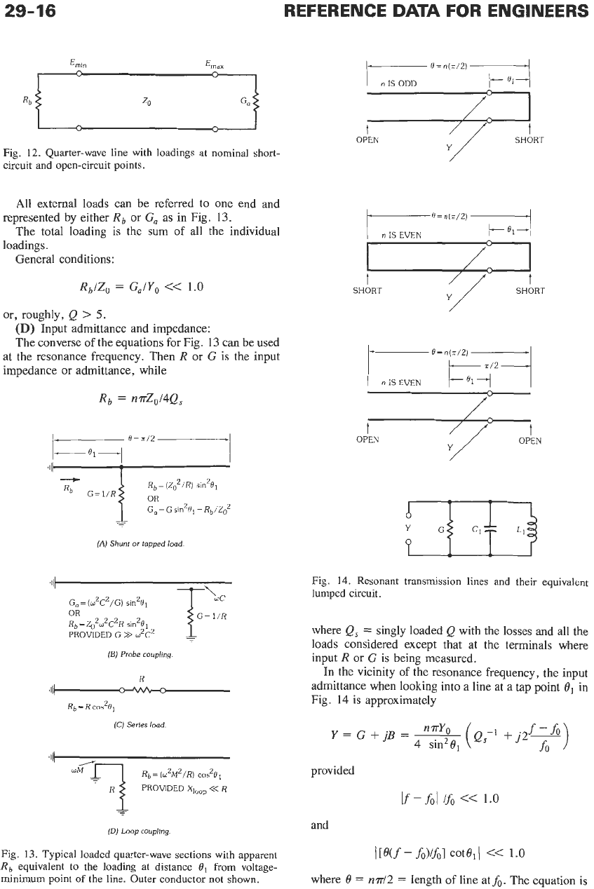
Fig.
12.
Quarter-wave line with loadings at nominal short-
circuit and open-circuit points.
All external loads can be referred to one end and
The total loading is the sum of all the individual
General conditions:
represented by either
Rb
or
G,
as in Fig.
13.
loadings.
RblZo
=
G,/Yo
<<
1.0
or, roughly,
Q
>
5.
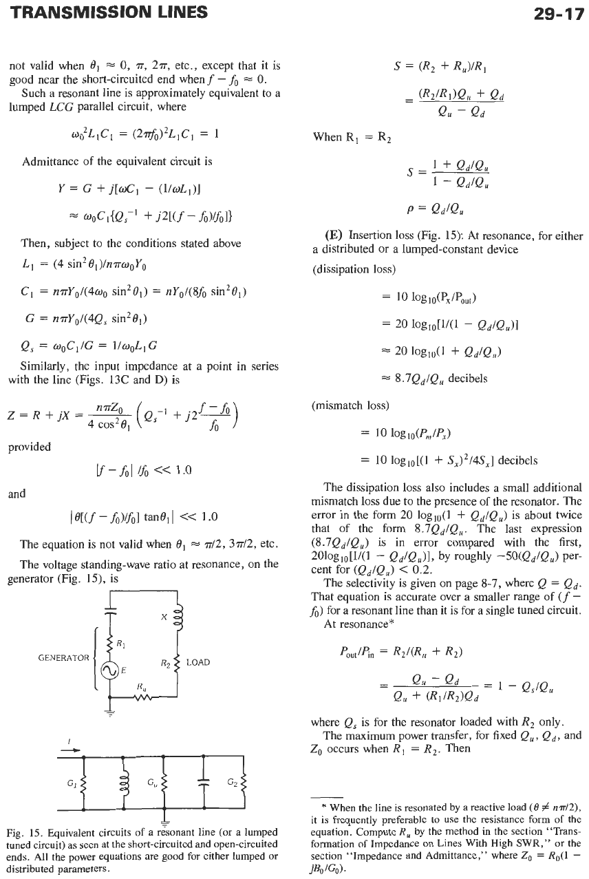
(D)
Input admittance and impedance:
The converse of the equations for Fig.
13
can be used
at the resonance frequency. Then
R
or
G
is the input
impedance or admittance, while
Rb
=
n.nZo/4Q,
Rb= (Z:/R)
sin2R1
G,=Gs~n2R1=Rb/Zoz
-
Rb
G=l/R
OR
(A)
Shunt
or
topped
load
(E)
Probe
coupling
R
'IIl-2-w-z-
R~
=
R
C&e1
(C)
Series
load.
(DJ
Loop coupling.
Fig.
13.
Typical loaded quarter-wave sections with apparent
R
e uivalent to the loading at distance
0,
from voltage-
minimum point
of
the line. Outer conductor not shown.
P
.q
0
=
n(=/2)
~4
n
IS
ODD
OPEN SHORT
SHORT SHORT
t
OPEN
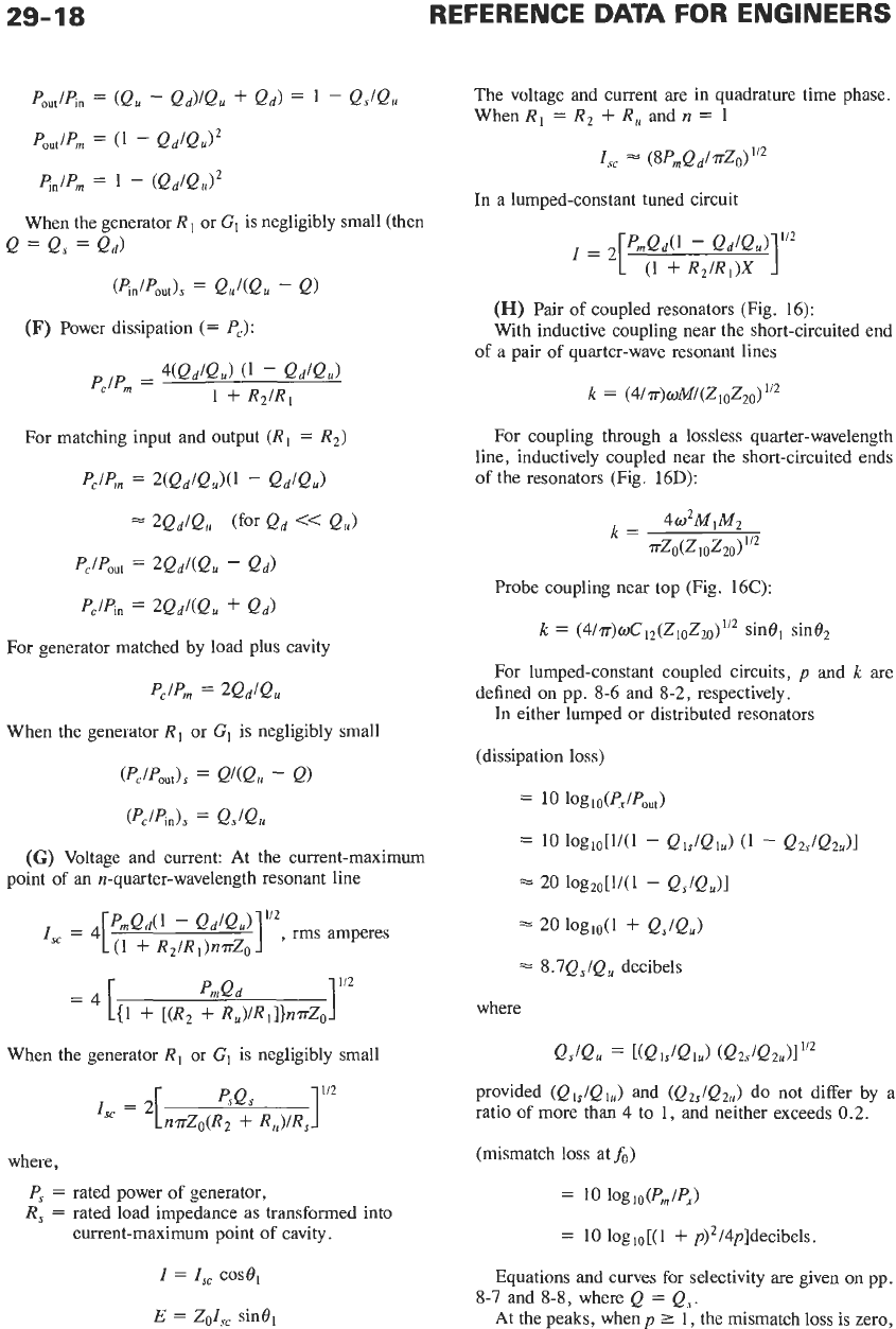
Fig.
14.
Resonant transmission lines and their equivalent
lumped circuit.
where
Q,
=
singly loaded
Q
with the losses and all the
loads considered except that at the terminals where
input
R
or
G
is being measured.
In
the vicinity
of
the resonance frequency, the input
admittance when looking into
a
line at a tap point
O1
in
Fig.
14
is approximately
provided
and
where
8
=
nd2
=
length
of
line atfo. The equation
is
TRANSMISSION
LINES
29-17
not valid when
8,
=
0,
77,
277,
etc., except that it is
good near the short-circuited end when
f
-
fo
=
0.
Such a resonant line is approximately equivalent to a
lumped
LCG
parallel circuit, where
o&C1
=
(24)2L,C,
=
1
Admittance of the equivalent circuit is
Y
=
G
+
j[d,
-
(l/~L1)]
a
ooCi{QS-’
+
j2[(f
-
fo)/fII
Then, subject to the conditions stated above
L~
=
(4
sin281)/n.irwoYo
C1
=
n?r~~/(4o~
sin201)
=
nYo/(8fo sin201)
G
=
n.irY0/(4Q,
sin2@,)
Q,
=
woCI/G
=
l/ooLiG
Similarly, the input impedance at a point in series
with the line (Figs.
13C
and
D)
is
provided
and
I
@[(f
-
fo)/fI
tan@,
I
<<
1.0
The equation is not valid when
O1
77/2, 3~12,
etc.
The voltage standing-wave ratio at resonance,
on
the
generator (Fig. 15), is
GENERATOR
I
When
R,
=
R,
1
f
1
-
QdQ,
S=
P
=
QdQ,
(E)
Insertion loss (Fig.
15):
At resonance, for either
a distributed or a lumped-constant device
(dissipation loss)
=
10 ~oglo(px~pout)
=
20
lOgio[1/(1
-
Qd/Q,)l
20
lOgio(1
+
Qd/Q,)
=
8.7Qd/Q,
decibels
(mismatch
loss)
=
10
loglo(Pm/P,)
=
10
loglo[(l
+
S,)2/4S,]
decibels
The dissipation loss also includes a small additional
mismatch loss due to the presence of the resonator. The
error in the form
20
loglo(l
+
Qd/Q,)
is about twice
that of the form
S.7Qd/Q,.
The last expression
(8.7Qd/Q,)
is in error compared with the first,
2010gio[1/(1
-
Qd/Q,)l,
by roughly
-5O(Qd/Q,)
Per-
cent for
(Qd/Q,)
<
0.2.
The selectivity is given
on
page
8-7,
where
Q
=
Qd.
That equation is accurate over a smaller range of
(f
-
fo)
for a resonant line than it is for a single tuned circuit.
At resonance*
LOAD
c
Fig.
15.
Equivalent circuits
of
a resonant line (or a lumped
tuned circuit) as seen
at
the short-circuited and open-circuited
ends.
All
the power equations are good for either lumped or
distributed parameters.
where
Q,
is for the resonator loaded with
R2
only.
Zo
occurs when
R,
=
R,.
Then
The maximum power transfer,
for
fixed
Qu,
Qd,
and
*
When the line is resonated by a reactive load
(0
#
n.rr/2),
it is frequently preferable to
use
the resistance form of the
equation. Compute
R,
by the method in the section “Trans-
formation
of
Impedance on Lines With High SWR,” or the
section “Impedance and Admittance,” where
Z,
=
Ro(l
-
jBoJG0).
29-18
REFERENCE
DATA
FOR ENGINEERS
For matching input and output
(R1
=
R2)
PclPm
=
VQd/Qu)(l
-
Qd/Qu)
2Qd/Qu
(for
Qd
<<
e,)
pc/pout
=
2Qd/(Qu
-
Qd)
Pclpin
=
2Qd/(Qu
f
Qd)
For generator matched by load plus cavity
PclPm
=
2QdlQu
When the generator
R,
or
GI
is negligibly small
(Pc/pout)s
=
Q4Qu
-
Q)
(PJpids
=
Qs/Qu
(G)
Voltage and current: At the current-maximum
point
of
an n-quarter-wavelength resonant line
When the generator
R1
or
G1
is negligibly small
Is‘
=
2[n~Zo(Rz
psQs
+
R,)/R,
I“,
where,
P,
=
rated power of generator,
R,
=
rated load impedance as transformed into
current-maximum point
of
cavity.
I
=
I,,
case,
E
=
Z0I,
sine,
The voltage and current are in quadrature time phase.
When
R,
=
R,
+
R,
and
n
=
1
I,,
(8PmQd/?rzo)1’2
In a lumped-constant tuned circuit
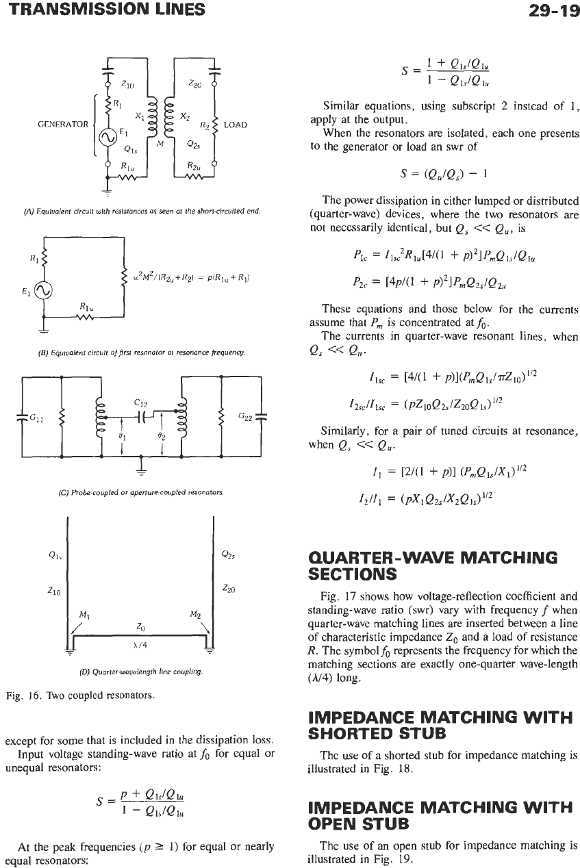
(H)
Pair
of
coupled resonators (Fig. 16):
With inductive coupling near the short-circuited end
of
a pair of quarter-wave resonant lines
For coupling through a lossless quarter-wavelength
line, inductively coupled near the short-circuited ends
of
the resonators (Fig. 16D):
Probe coupling near top (Fig. 16C):
k
=
(~/T)~C,~(Z~,Z~~)~’~
sinel sine,
For lumped-constant coupled circuits,
p
and
k
are
In either lumped or distributed resonators
defined on pp. 8-6 and
8-2,
respectively.
(dissipation loss)
=
10
loglo(p,~pout)
=
10
log~o[l/(l
-
QlJQlu)
(1
-
Q~s/Qdl
20
logzo[l/(l
-
Qs/Q,)l
20
lOgio(1
+
QJQJ
=
8.7Q,/Qu
decibels
where
QJQ,
=
[(QIJQIJ
(Qz,/Qz,)I~’~
provided
(Ql,/Ql,)
and
(Qz,/Qz,)
do not differ by a
ratio
of
more than 4 to
1,
and neither exceeds
0.2.
(mismatch
loss
at
fo)
=
10
log10(Pm/P,)
=
10 loglo[(l
+
p)2/4p]decibels.
Equations and curves for selectivity are given on pp.
At the peaks, when
p
2
1, the mismatch loss is zero,
8-7
and
8-8,
where
Q
=
Q,.
TRANSMISSION LINES
29-19
GENERATOR
(A)
Equiualent circuit wlth resistances as seen at the short-circuited end.
(5)
Equiualent circuit
of
first
resonator at resonance frequency.
+
(C)
Probe-coupled
or
aperture-coupled resonators.
(D)
Quarter-wouelengfh line coupling.
Fig.
16.
Two
coupled
resonators.
except for some that is included in the dissipation loss.
Input voltage standing-wave ratio at
fo
for equal or
unequal resonators:
P
+
QiJQi,
S=
1
-
Qis/Qlu
At the peak frequencies
(p
2
1)
for equal or nearly
equal resonators:
Similar equations, using subscript
2
instead of
1,
When the resonators are isolated, each one presents
apply at the output.
to the generator or load an swr
of
S
=
(QJQ,,
-
1
The power dissipation in either lumped or distributed
(quarter-wave) devices, where the two resonators
are
not necessarily identical, but
Q,
<<
Qu,
is
PIC
=
IiS~R1,[4/(1
+
~)~lPrnQ~s/Qiu
P2c
[4~/(1
+
pj2IPrnQzs/Q2u
These equations and those below
for
the currents
The currents in quarter-wave resonant lines, when
assume that
P,
is
concentrated at
fo.
Q,
<<
Q,.
11,
=
[4/(1
+
~)l(P,QiJ~zio)"~
12sc/Iisc
=
(PZ~OQ~~/ZZOQ
1s)
Similarly, for
a
pair of tuned circuits at resonance,
when
Qs
<<
Q,.
I1
=
P(1
+
p)l
(f'mQ1s/X1)1'2
12/11
=
(PXIQZ~/X~QI~)"~
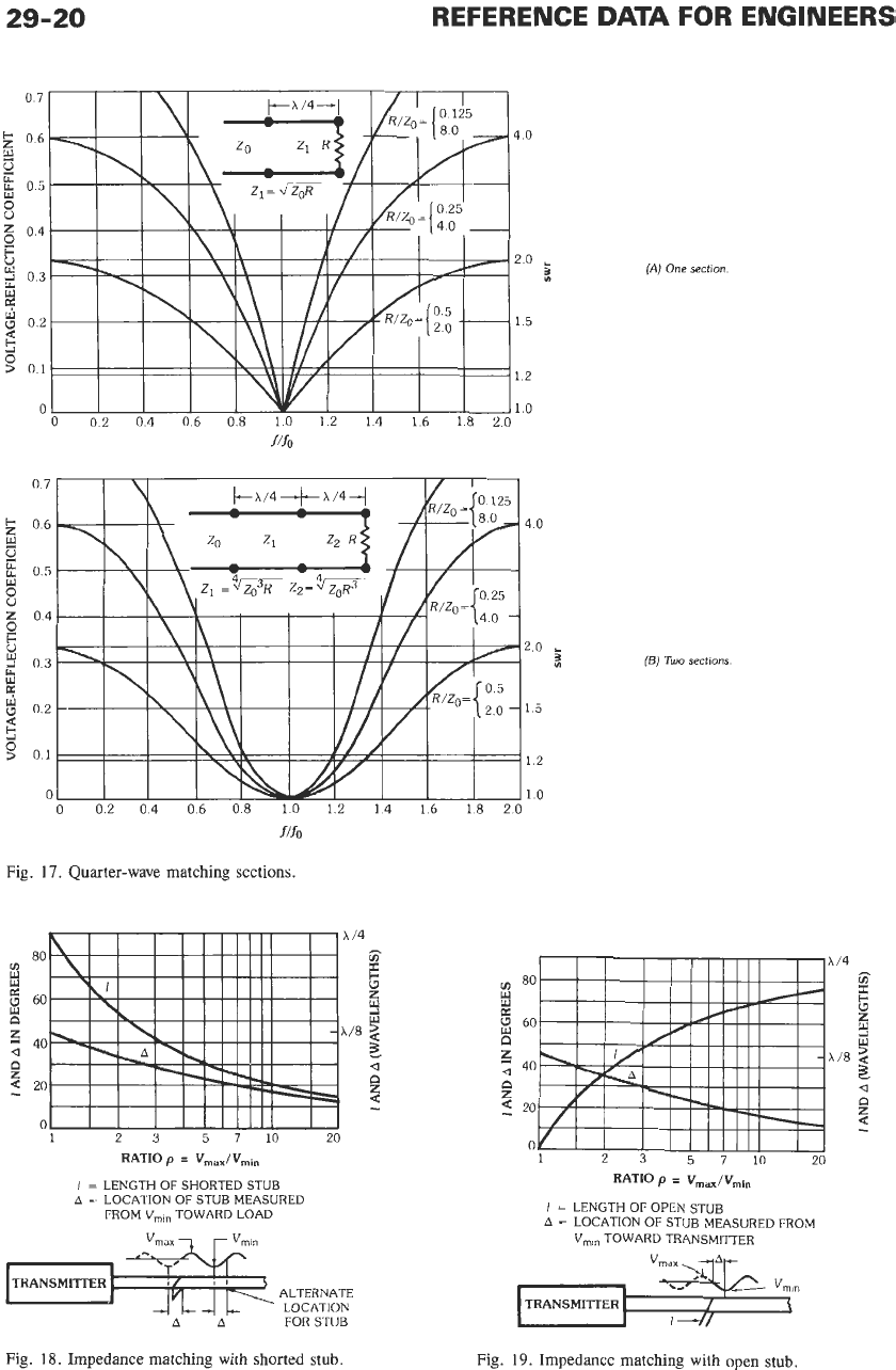
QUARTER-WAVE MATCHING
SECTIONS
Fig.
17
shows how voltage-reflection coefficient and
standing-wave ratio (swr) vary with frequency
f
when
quarter-wave matching lines are inserted between a line
of characteristic impedance
Z,
and a load of resistance
R.
The symbol& represents the frequency for which the
matching sections are exactly one-quarter wave-length
(h/4)
long.
IMPEDANCE MATCHING
WITH
SHORTED
STUB
The use of a shorted stub for impedance matching is
illustrated in Fig.
18.
IMPEDANCE MATCHING WITH
OPEN STUB
The use of an open stub for impedance matching is
illustrated in Fig.
19.
29-20
REFERENCE
DATA
FOR ENGINEERS
Fig.
17.
Quarter-wave matching sections.
A
80
m
B
g
60
n
z
a
40
A
0
2
20
I
I11111
0
1
23
5710
20
RATlOp
=
Vma,/Vmin
I
=
LENGTH
OF
SHORTED STUB
A
=
LOCATION
OF
STUB MEASURED
FROM
V,,,
TOWARD LOAD
TRANSMITTER
/
,I
J7-J
P
ALTERNATE
LOCATION
AA
FOR STUB
Fig.
18.
Impedance matching with shorted stub.
(A)
One section
(E)
Two
sections.
/4
c
z
3
w
/8
5
2
a
n
4
z
m
80
w
W
60
0
z
a
40
n
4
20
z
0
1
2
3
5710
20
RATIO
p
=
Vmax/Vmin
I
=
LENGTH
OF
OPEN STUB
A
=
LOCATION
OF
STUB MEASURED FROM
V,,, TOWARD TRANSMITTER
TRANSMITTER
Fig.
19.
Impedance matching with open stub.
.:4
n
5
TRANSMISSION LINES
29-21
v
30:F
20
--
LENGTH OF
LINE IN
ELECTRICAL
DEGREES
v
40
v
=
60
--40
-
-
-
-
-
-
-
150
-
-
-
-
200
--
-
-
-
300
\
-..
\
\
--
200
-
-
-
-
--
150
-
-
--
--
100
01
oooiz
L
0
0
07
05
-
20
-
-
-
-
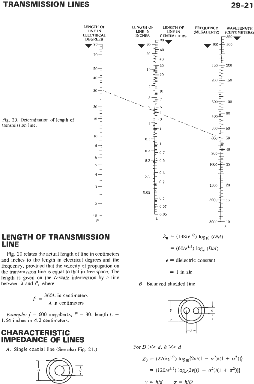
Fig.
20.
Determination
of
length
of
15
-
-
transmission
line.
-
-
-
10
7
-
-
8-
-
-
-
6-
5-
4-
-
-
-
3-
-
2-
1.5
-
LENGTH
OF
TRANSMISSION
LINE
\
\
\
,
500=160
\
60‘0’~
Fig.
20
relates the actual length of line in centimeters
and inches to the length in electrical degrees and the
frequency, provided that the velocity
of
propagation on
the transmission line is equal to that in free space. The
length
is
given on the L-scale intersection by a line
between
A
and
I“,
where
-
--
50
-
360L in centimeters
1-
A
in centimeters
Example:
f
=
600
megahertz,
1“
=
30, length
L
=
1.64 inches or 4.2 centimeters.
-
1000-F
CHARACTERISTIC
IMPEDANCE
OF
LINES
A.
Single coaxial line (See also Fig. 21.)
-
-
-
30
-
-
Zo
=
(138/~”~) loglo
(Dld)
=
(60/~”’) log,
(Dld)
E
=
dielectric constant
=
1
in air
B.
Balanced shielded line
For
D
>>
d,
h
>>
d
Z,
=
(276/~”*) log~0{2v[(l
-
d)/(l
+
d)]}
=
(120/€”2)
log,{2v[(l
-
&)/(1
+
d)]}
v
=
h/d
u
=
h/D