Middleton W.M. (ed.) Reference Data for Engineers: Radio, Electronics, Computer and Communications
Подождите немного. Документ загружается.

29-22
REFERENCE
DATA
FOR ENGINEERS
0
to
220
Ohms
Zo
=
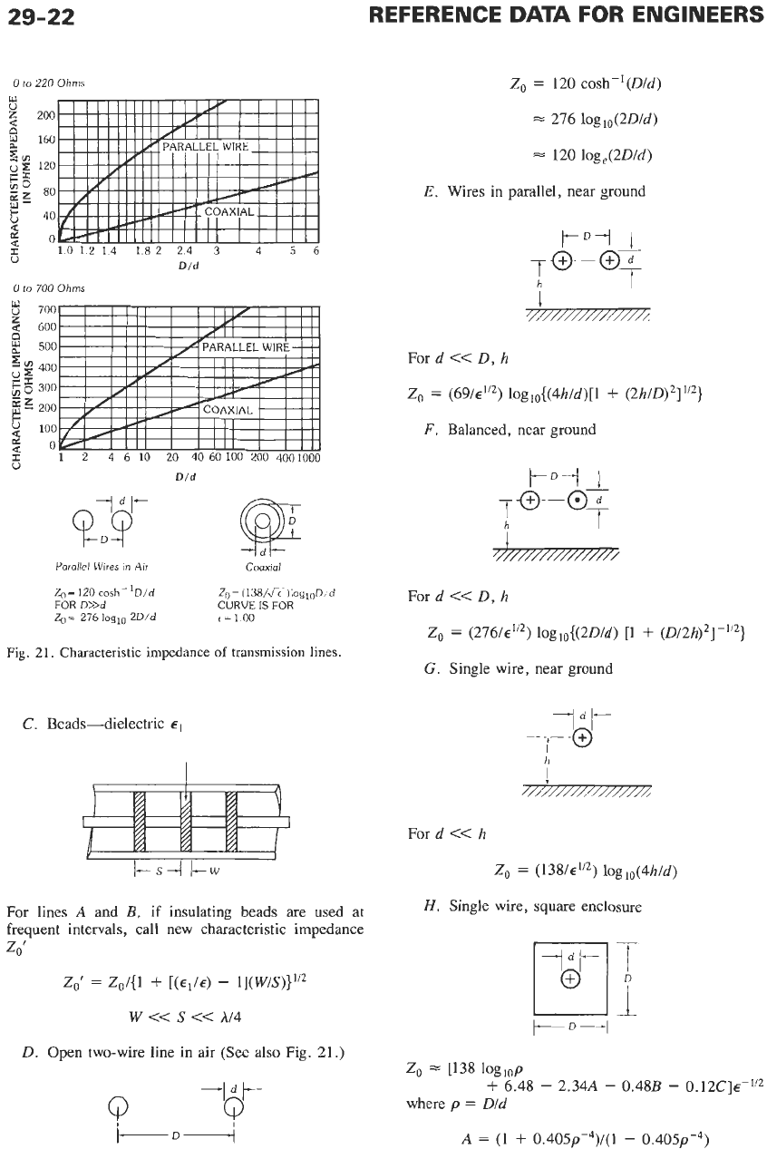
120 cosh-’(D/d)
w
u
z
d
La
Y
a
2,
25
$0
gE
G
2
d
cz
0
200
160
120
80
40
0
1012
14
1.82
24
3
4
5
6
Did
276 loglo(2D/d)
=
120 loge(2D/d)
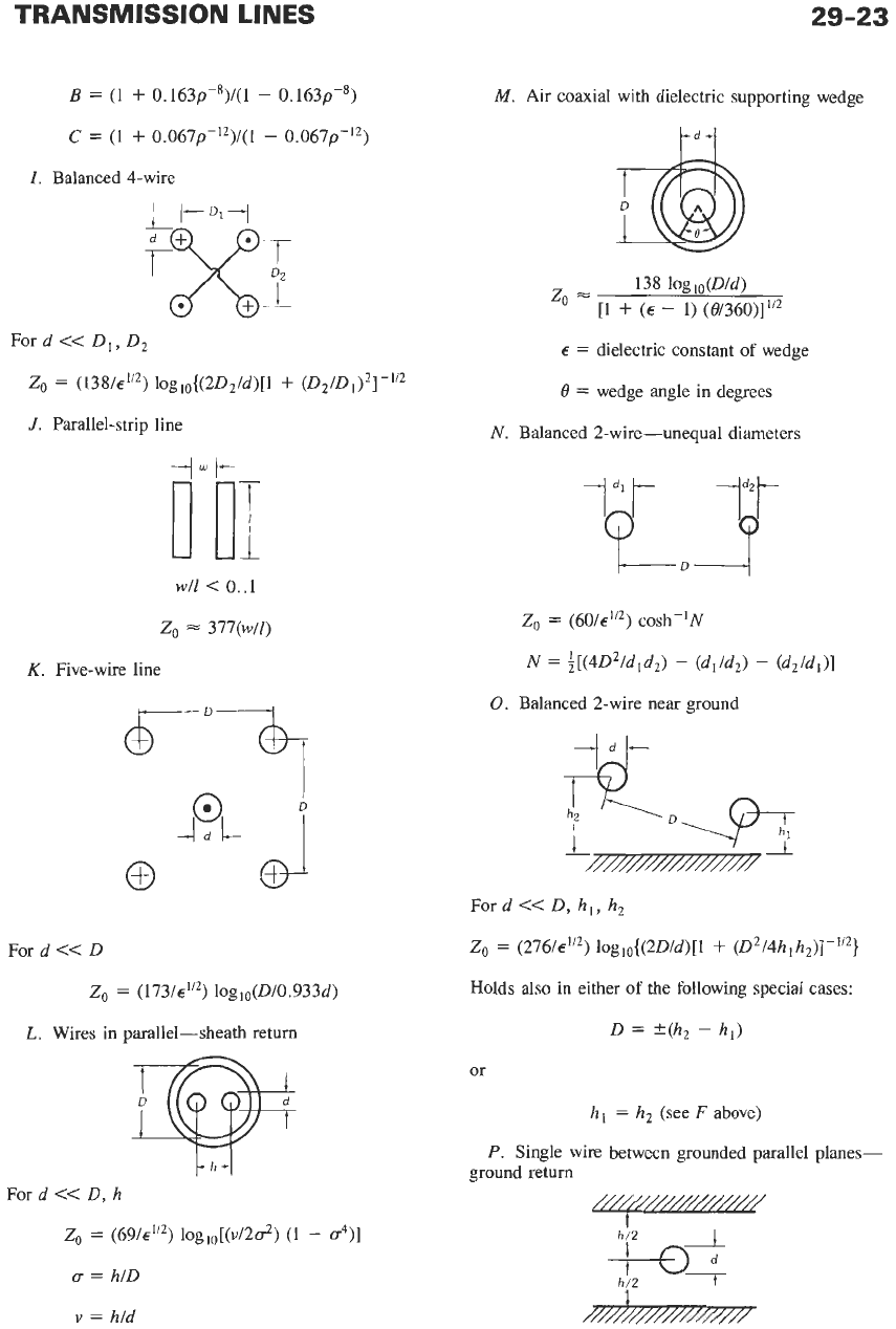
E.
Wires in parallel, near ground
h
I
0
to
700
Ohms
I
8
700
5
600
CI
3
500
E
400
2
8
300
c
8
200
g
100
%
0-
I
111
I
I
I I
Z
1
2
4
6
10
20
40
60
100
200
4001000
0
Dld
4dl-
QJ
For d
<<
D, h
Zo
=
(691~”~) loglo{(4h/d)[l
+
(2h/D)2]
”’}
F.
Balanced, near ground
Parallel
Wires
in Air
Coaxial
Zo=
120
coshKID/d
Zo
=
(138/J<)logl0D,’d
Ford
<<
D, h
20
=
276
loglo
2D/d
FOR
D>>d
CURVE
IS
FOR
r=lOO
Zo
=
(276/~”~) 10g10{(2D/d) [l
+
(D/2h)2]-1’2}
G.
Single wire, near ground
Fig.
21.
Characteristic impedance
of
transmission lines.
-
C.
Beads-dielectric
ldt
-,-
-@
l-s4
I-w
For lines
A
and
B,
if insulating beads are used at
frequent intervals, call new characteristic impedance
ZO’
Z,‘
=
ZO/{l
+
[(E1/€)
-
l](W/S)}1/2
W
<<
S
<<
h/4
D.
Open two-wire line in
air
(See also Fig. 21.)
4
d
I-
Q
+Dl
i
For
d
<<
h
Z,
=
(138/~”~) loglo(4h/d)
H.
Single wire, square enclosure
Zo
s=
[138 loglop
+
6.48
-
2.34A
-
0.48B
-
0.12C]~-”’
where p
=
D/d
A
=
(1
+
0.405p-4)/(1
-
0.405~-~)
TRANSMISSION
LINES
29-23
B
=
(1
+
0.163~-*)/(1
-
0.163~-~)
C
=
(I
+
0.067p-’2)/(1
-
O.067p-l2)
I.
Balanced 4-wire
Ford
<<
D,, D,
20
=
(138/~”’) 10gl0{(2D,/d)[l
+
(D2/D1)2]-“2
J.
Parallel-strip line
-I+
0
01
w/l
<
0..1
2,
=
377(W/Z)
K.
Five-wire line
For d
<<
D
2,
=
(173/~”’) loglo(D/0.933d)
L.
Wires in parallel-sheath return
For
d
<<
D, h
Zo
=
(69/~’/’) 10glO[(v/2~’)
(1
-
u4)]
u
=
hiD
M.
Air coaxial with dielectric supporting wedge
tdl
138 lOglo(D/d)
2,
=
[l
+
(E
-
1) (0/360)]
’”
E
=
dielectric constant of wedge
B
=
wedge angle in degrees
N. Balanced 2-wire-unequal diameters
1
dl
t-
-ld*t-
Q
0
Zo
=
(60/~”’) cosh-’N
N
=
$[(4D2/d,d,)
-
(d,/d,)
-
(dZ/dl)]
0.
Balanced 2-wire near ground
#
“i
‘D*
......................
Ford
<<
D, h,, h,
2,
=
(276/~”’) loglo{(2D/d)[l
+
(D2/4h,hz)]-1/2}
Holds also in either
of
the following special cases:
D
=
f(h2
-
h,)
or
hl
=
h, (see
F
above)
P.
Single wire between grounded parallel planes-
ground return
v
=
hid
29-24
REFERENCE
DATA
FOR ENGINEERS
For d/h
<
0.75
zo
=
(138/6’12)
lOglo(4h/Td)
Q.
Balanced line between grounded parallel planes
-
Ford
<<
D, h
4 h tanh( nD/2 h)
(
nd
Z,
=
(276/~”’) loglo
R.
Balanced line between grounded parallel planes
h/4
/-
For d
<<
h
Z,
=
(276/~‘”) 1ogI0(2h/nd)
S.
Single wire in trough
d
t
For d
<<
h, w
Z,
=
(138/~”~)
loglo (4w tanyw))
T.
Balanced 2-wire line in rectangular enclosure
w/2
D, w,
h
For d
<<
Zo
=
(276/~”’
)
[
loglo (4h tanh(nD/2h))
nd
-
5
log,,
(U)]
m=l
1
-
vm2
where
sinh( nD/2h) sinh(nD/2h)
cosh(mw/2h) sinh(mmd2h)
urn
=
v,
=
U.
Eccentric line
Z,
=
(60/~”~) cosh-’U
U
=
[(D/d)
+
(d/D)
-
(4c2/dD)]
V.
Balanced 2-wire line in semi-infinite enclosure
m
kkyL)j
For d
<<
D, w, h
Z,
=
(276/d”) 10g~~[2w/.rrd(A~’~)]
where
A
=
cosec2(nD/w)
+
cosech2(2.rrh/w)
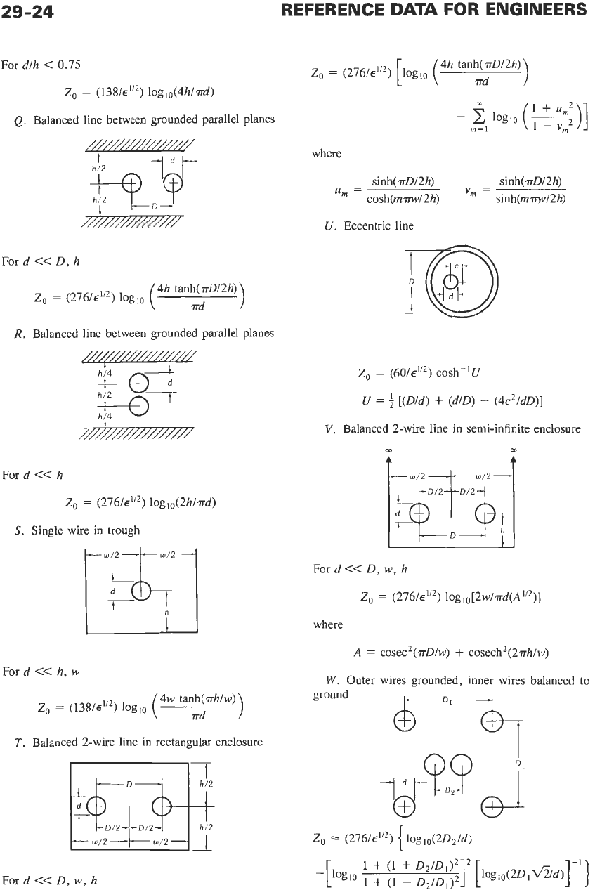
W.
Outer wires grounded, inner wires balanced to
ground
I
d
Z,
=
(276/~”~) loglo(2Dz/d)
I
TRANSMISSION LINES
29-25
X.
Split thin-walled cylinder
For
8
small:
Zo
e
129/10g10(4D/d)
Courtesy
of
Electronic Engineering
Y.
Slotted air line
When a slot is introduced into an air coaxial line for
measuring purposes, the increase in characteristic im-
pedance in ohms, compared with a normal coaxial line,
is less than
AZ
=
0.0382
where
8
is the angular opening of the slot in radians.
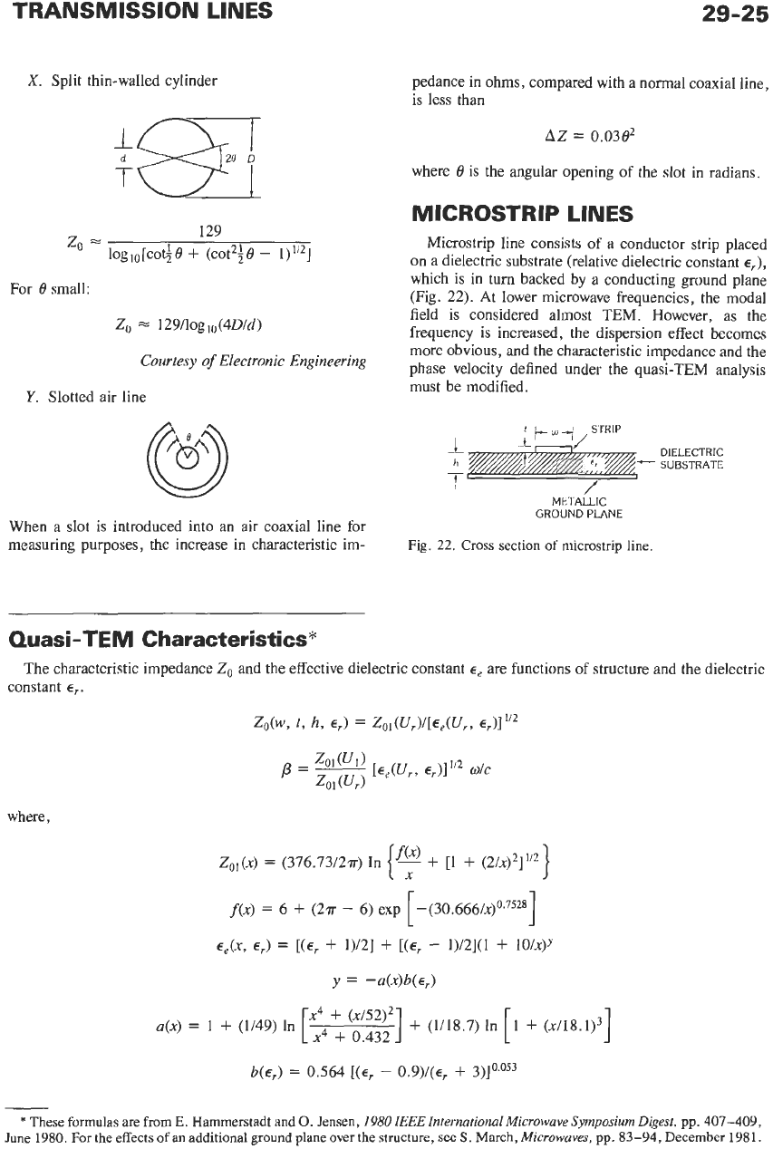
MICROSTRIP LINES
Microstrip line consists of a conductor strip placed
on a dielectric substrate (relative dielectric constant
el),
which is in turn backed by a conducting ground plane
(Fig.
22).
At lower microwave frequencies, the modal
field is considered almost TEM. However, as the
frequency is increased, the dispersion effect becomes
more obvious, and the characteristic impedance and the
phase velocity defined under the quasi-TEM analysis
must be modified.
L
DIELECTRIC
h
SUBSTRATE
f
/
META~LIC
GROUND PLANE
Fig.
22.
Cross section of microstrip line.
Quasi-TEM Characteristics*
The characteristic impedance
Zo
and the effective dielectric constant
E,
are functions of structure and the dielectric
constant
E,.
zO(w,
t,
h,
E,)
=
ZOI(UrY[Ee(Ur,
E,)I’”
p=-
zol(U1)
[Ee(U,,
EJ”2
w/c
Zol(ur)
where,
1
1
Zo,(x)
=
(376.73/2~)
In
-
+
[l
+
(2/~)~]~”
-(30.666/~)~.~~~~
{f:)
[
f(x)
=
6
+
(2a
-
6)
exp
EJX,
E,)
=
[(E,
+
1)/2]
+
[(E,
-
1)/2](1
+
lO/X)Y
~~4~(~~~~~]
+
(U18.7) In
I
a(x)
=
1
+
(1/49) In
b(~,)
=
0.564
[(E,
-
0.9)/(~,
+
3)lo.Os3
*
These formulas are from
E.
Hammerstadt and
0.
Jensen,
1980
IEEE
International Microwave Symposium Digest,
pp.
407-409,
June
1980.
For the effects
of
an
additional ground plane over the structure, see
S.
March,
Microwaves,
pp,
83-94,
December
1981.
29-26
REFERENCE DATA FOR ENGINEERS
x
is either
U,
=
w/h
+
(tlrr)
In
1
+
4
exp(1)
[
1
+
llcosh (E,
-
1)112]/2
[
t
coth’ (6.517 wlh)
or
1
4
exp(1)
U1
=
w/h
+
(tlrr)
In
1
+
[
t
coth2 (6.517 wlh)”*
depending
on
which is called for in the above equations. Note that
t
+
0,
both
U,
and
U1
approach wlh.
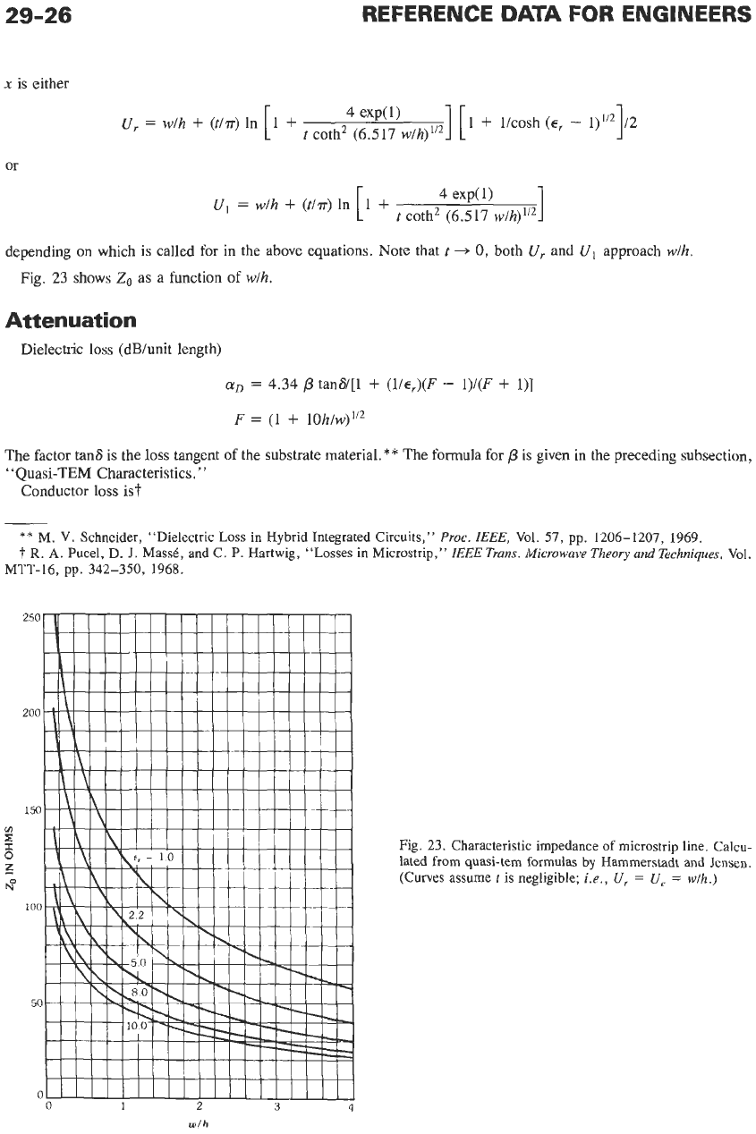
Fig.
23
shows
Zo
as a function of wlh.
Attenuation
Dielectric
loss
(dB/unit length)
aD
=
4.34
p
tans/[l
+
(l/q)(F
-
1)/(F
+
l)]
F
=
(1
+
10h/w)1’2
The factor tans is the loss tangent of the substrate material.** The formula for
p
is given in the preceding subsection,
“Quasi-TEM Characteristics.”
Conductor
loss
ist
**
M.
V. Schneider, “Dielectric Loss in Hybrid Integrated Circuits,”
Proc.
IEEE,
Vol. 57, pp. 1206-1207, 1969.
t
R.
A.
Pucel, D.
J.
MassB, and C.
P.
Hartwig, “Losses in Microstrip,”
ZEEE
Trans.
Microwave
Theory
and
Techniques,
Vol.
MTT-16, pp. 342-350, 1968.
Fig. 23. Characteristic impedance of microstrip line. Calcu-
lated
from
quasi-tem formulas by Hammerstadt and Jensen.
(Curves assume
tis
negligible;
i.e.,
U,
=
U,
=
w/h.)
TRANSMISSION LINES
29-27
a,
=
(4.34R,/rhZo)[1
-
(~’/4h)~] (1
+
hlw’
+
(hlmy’) [ln(4m/t
+
1)
-
(1
-
t/w)/(l
+
t/4m)]}
=
(4.34R,/rhZO)
[l
-
(w‘/4h)’]
(1
+
hlw’
+
(h/myf)[ln(2h/t
+
1)
-
(1
+
t/h)/(l
+
t/2h)]}
1/2r
<
w/h
5
2
’1
A
L’.*.’
+
(h/m’)[ln (2hlt
+
1)
-
(1
+
t/h)/(l
+
t/2h)]}
1
w ‘lrh
w’12h
+
0.94
8.68 R,
[$
+
-
I
I’,
Y”
-
hZo{w‘/h
+
(2/.rr) In [2m (w’/2h
+
0.94)]}2
I’
w/h
>
2
where
w‘
=
w
+
Aw
and for 2t/h
<
w/h, 1/2r
Aw
=
(t/.rr)
In (4m/t
+
1)
w/h
5
1/2~
=
(t/r)
In (2hlt
+
1)
w/h
2
1/2r
The quantity Z, is the characteristic impedance dis-
cussed before, and R, is the surface resistivity. Typical-
ly, R,
=
2.61
X
10-7qffor copper.
Frequency- Dependent
Characteristics
As
the microstrip mode is not purely TEM, both Zo
and
E,
are functions of frequency.$
Zo(f)
=
~o(O)[~e(O)/~e(f)l “2[~e(f)
-
11/[~e(O)
-
11
ee(f)
=
E,
-
[E,
-
~,(0)1/[1
+
G(f!(J’l
where,
fp
=
Zo(0)/(2Poh)
po
=
free-space permeability.
G
=
(r2/12)[(~,
-
l)/~,(O)][Z0(0)/60]~~~
In
the above, Zo(0) and
E,(O)
are dc values and are
obtained from the formulas in “Quasi-TEM
Characteristics.
’
’
$
E.
Hammerstadt and
0.
Jensen,
1980
IEEE
International
Microwave
Symposium
Digest,
pp. 407-409,
June
1980.
Power- Handling Capacity
For a microstrip line composed of a strip %z-inch
wide
on
a Teflon-impregnated fiberglass base ?&inch
thick:
(A)
At 3000 megahertz with
300
watts cw, the
temperature under the strip conductor has been mea-
sured at 50” Celsius rise above 20” Celsius ambient.
(B)
Under pulse conditions, corona effects appear at
the edge of the strip conductor for pulse power of
roughly
10
kilowatts at 9000 megahertz.
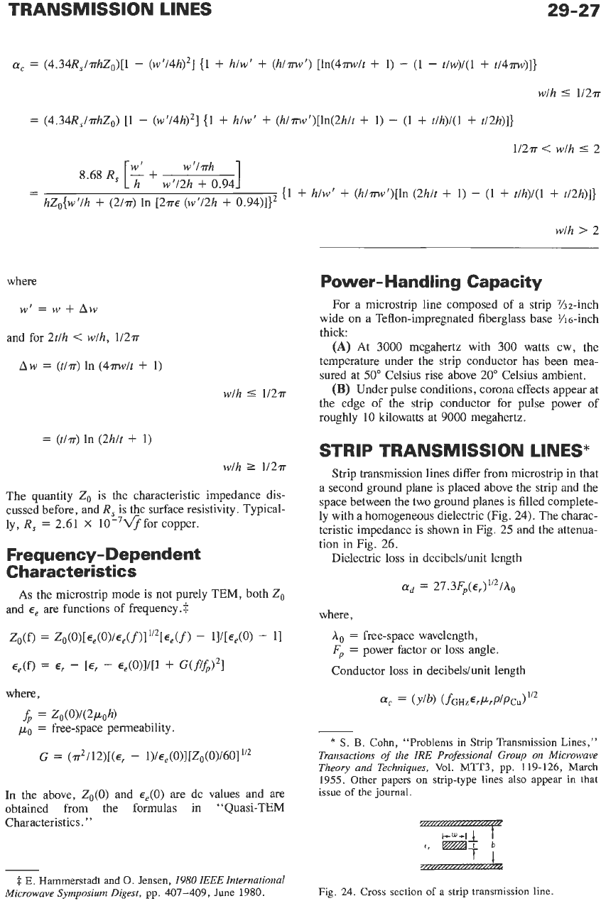
STRIP TRANSMISSION LINES*
Strip transmission lines differ from microstrip in that
a
second ground plane is placed above the strip and the
space between the two ground planes is filled complete-
ly with a homogeneous dielectric (Fig. 24). The charac-
teristic impedance is shown in Fig. 25 and the attenua-
tion in Fig. 26.
Dielectric loss in decibeldunit length
ad
=
27.3Fp(~,)1’2/Ao
where,
A,
=
free-space wavelength,
Fp
=
power factor or
loss
angle.
Conductor loss in decibeldunit length
*
S.
B.
Cohn,
“Problems in Strip Transmission Lines,”
Transactions of the
IRE
Professional Group on Microwave
Theory and Techniques,
Vol. MTT3, pp. 119-126, March
1955. Other papers on strip-type lines also appear
in
that
issue
of
the journal.
f‘
f
J
Fig. 24. Cross section
of
a strip transmission line
29-28
REFERENCE DATA FOR ENGINEERS
0.1
0.2
0.3
0.5
0.7
10
23
wlb
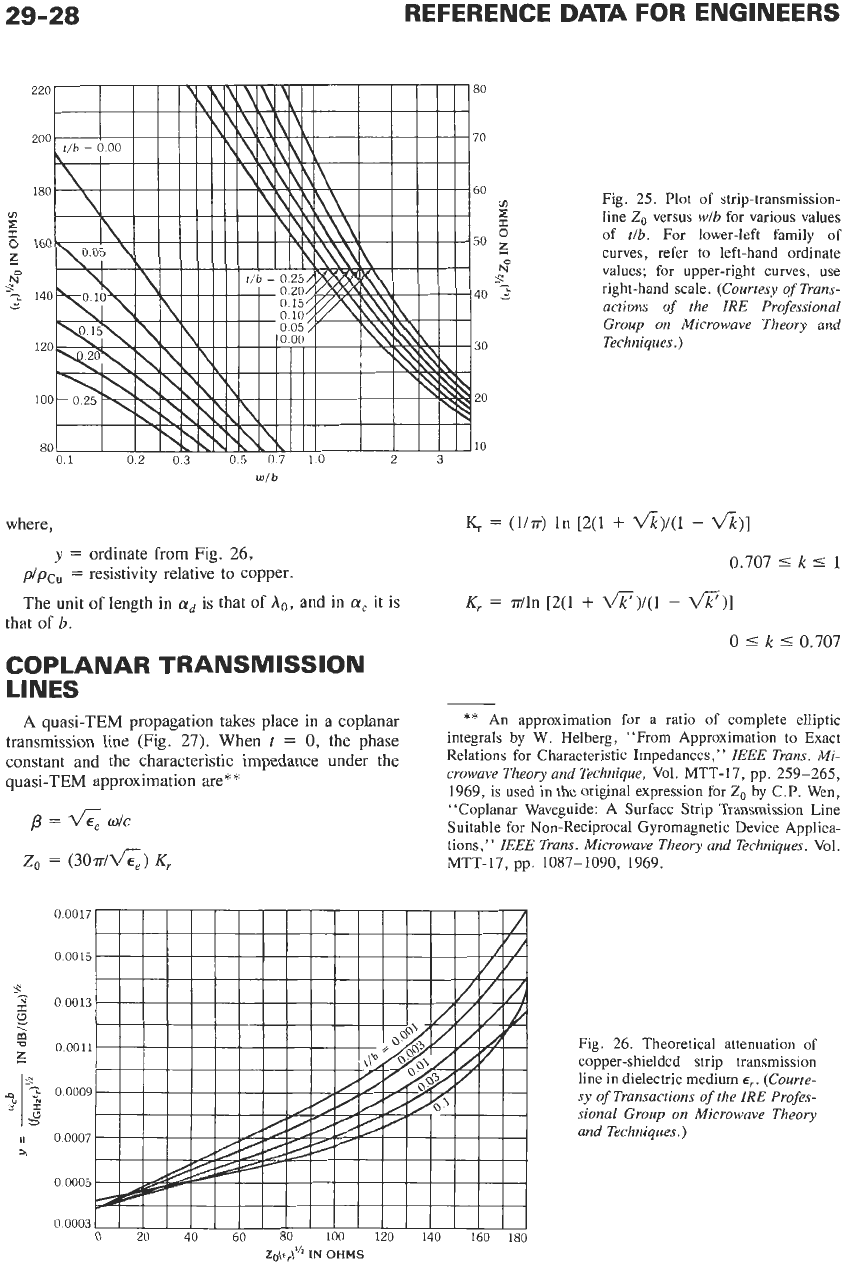
Fig. 25. Plot of strip-transmission-
line
Zo
versus
wlb
for various values
of
tlb.
For lower-left family of
curves, refer to left-hand ordinate
values; for upper-right curves,
use
right-hand scale.
(Courtesy
of
Trans-
actions
of
the IRE Professional
Group
on
Microwave Theory and
Techniques.
)
y
=
ordinate from Fig.
26,
pipc,
=
resistivity relative to copper.
0.707
5
k
I
1
The unit
of
length
in
ad
is that
of
A,,,
and in
a,
it is
K,.
=
r/ln
[2(1
+
*)/(I
-
-11
that
of
b.
0
5
k
5
0.707
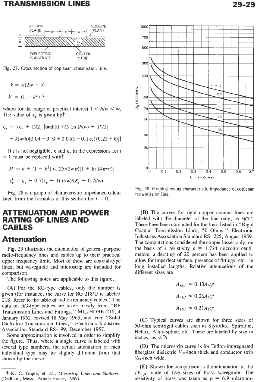
COPLANAR TRANSMISSION
LINES
A
quasi-TEM propagation takes place in a coplanar
transmission line (~i~. 27). When
t
=
0,
the phase
constant and the characteristic impedance under the
quasi-TEM approximation are*
*
**
An approximation for a ratio of complete elliptic
integrals by W. Helberg, “From Approximation to Exact
Relations for Characteristic Impedances,”
ZEEE Trans. Mi-
crowave Theory and Technique,
Vol.
MTT-17,
pp. 259-265,
1969, is used in the original expression for
Zo
by C.P. Wen,
“Coplanar Waveguide: A Surface Strip Transmission Line
Suitable for Non-Reciprocal Gyromagnetic Device Applica-
tions,”
IEEE Trans. Microwave Theory and Techniques.
Vol.
MTT-17, pp. 1087-1090, 1969.
p
=
6
dc
Z,
=
(3Ode)
K,
s-
r
s
m
a
z
,
I1
a
Fig.
26.
Theoretical attenuation of
copper-shielded strip transmission
line in dielectric medium
E,.
(Courte-
sy
of
Transactions
of
the
IRE
Profes-
sional Group
on
Microwave Theory
and Techniques.)
z~(c,.)”
IN
OHMS
TRANSMISSION LINES
29-29
DIELECTRIC
C~NTER
SUBSTRATE STRIP
Fig.
27.
Cross
section
of
coplanar transmission line.
k
=
s/(2w
+
s)
where for the range of practical interest
1
5
h/w
<
m.
The value of
E,
is given by?
E,
=
[(E,
+
1)/2] {tanh[0.775 In
(hlw)
+
1/75]
+
k(w/h)[0.04
-
0.7k
+
O.Ol(1
-
0.1
E,)
(0.25
+
k)]}
If
t
is not negligible, k and
E,
in the expressions for
t
=
0
must be replaced with?
k“
=
k
+
(1
-
k2) (1.25t/2w?r)[l
+
In (4?rs/t)]
E:
=
E,
-
0.7(~,
-
1)
(t/w)/(K,
+
0.7t/w)
Fig. 28 is a graph of characteristic impedance calcu-
lated from the formulas in this section for
t
=
0.
ATTENUATION AND POWER
RATING
OF
LINES AND
CABLES
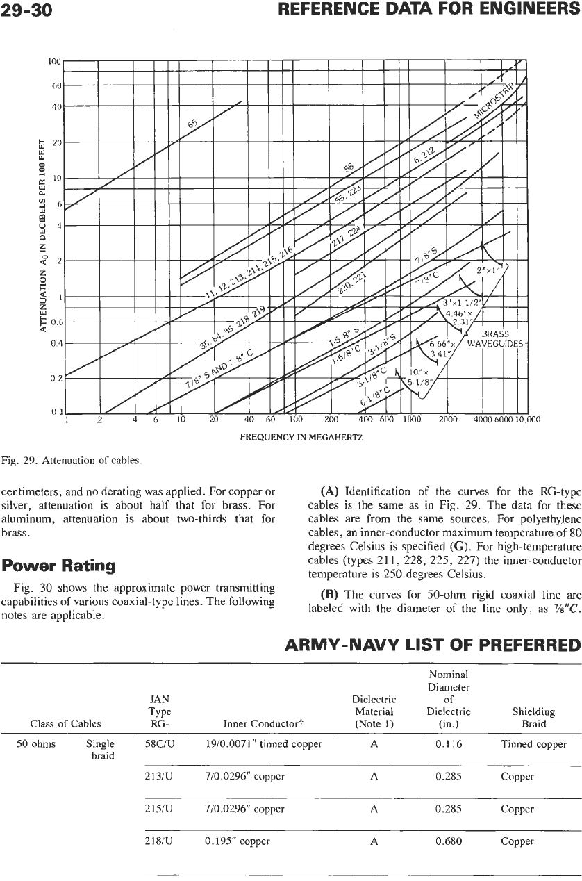
Attenuation
Fig. 29 illustrates the attenuation of general-purpose
radio-frequency lines and cables up to their practical
upper frequency limit. Most of these
are
coaxial-type
lines, but waveguide and microstrip are included for
comparison.
The following notes are applicable to this figure.
(A)
For the RG-type cables, only the number is
given (for instance, the curve for RG-218/U is labeled
218. Refer to the table of radio-frequency cables.) The
data on RG-type cables are taken mostly from
“RF
Transmission Lines and Fittings,” MIL-HDBK-216,
4
January 1962, revised
18
May 1965, and from “Solid
Dielectric Transmission
Lines,
”
Electronic Industries
Association Standard RS-199, December 1957.
Some approximation is involved in order to simplify
the figure. Thus, where a single curve is labeled with
several type numbers, the actual attenuation of each
individual type may be slightly different from that
shown by the curve.
7
K.
C.
Gupta, et.
al.,
Microstrip
Lines
and
Slotlines,
(Dedham, Mass.: Artech House,
1969).
k
=
s/(2w+s)
Fig.
28.
Graph showing characteristic impedance of coplanar
transmission line.
(B)
The curves for rigid copper coaxial lines
are
labeled with the diameter of the line only, as %“C.
These have been computed for the lines listed in “Rigid
Coaxial Transmission Lines, 50 Ohms,” Electronic
Industries Association Standard RS-225, August 1959.
The computations considered the copper losses only, on
the basis of a resistivity
p
=
1.724 microhm-centi-
meters; a derating of 20 percent has been applied to
allow for imperfect surface, presence of fittings, etc., in
long installed lengths. Relative attenuations of the
different sizes are
A~L/S,C
z
0.13A,/”
A~%J,
0.26A,/11
A,S,8,,
z
0.51A,/rr
(C)
Typical curves are shown for three sizes
of
50-ohm semirigid cables such as Styroflex, Spiroline,
Heliax, Alumispline, etc. These are labeled by size in
inches, as
%“S.
(D)
The microstrip curve is for Teflon-impregnated
fiberglass dielectric
?h
6-inch thick and conductor strip
Yiz-inch wide.
(E)
Shown for comparison is the attenuation in the
TE,,,
mode of five sizes of brass waveguide. The
resistivity of brass was taken as
p
=
6.9 microhm-
29-30
REFERENCE
DATA
FOR ENGINEERS
FREQUENCY
IN
MEGAHERTZ
Fig. 29. Attenuation of cables.
centimeters, and
no
derating was applied. For copper or
silver, attenuation is about half that for brass. For
aluminum, attenuation is about two-thirds that for
brass.
(A)
Identification of the curves for the RG-type
cables is the same as in Fig.
29.
The data for these
cables are from the same sources. For polyethylene
cables, an inner-conductor maximum temperature of
80
degrees Celsius is specified
(G).
For high-temperature
cables (types
21
1,
228;
225,
227)
the inner-conductor
temperature is
250
degrees Celsius.
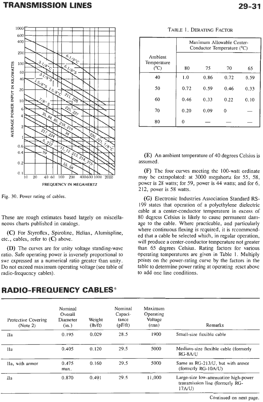
Power
Rating
-
Fig.
30
shows the approximate power transmitting
capabilities of various coaxial-type lines. The following
notes are applicable.
(B)
The curves for %ohm rigid coaxial line are
labeled with the diameter of the line only, as
7/s”C.
ARMY-NAVY
LIST
OF PREFERRED
Nominal
Diameter
JAN Dielectric
of
Type Material Dielectric Shielding
Class
of
Cables
RG-
Inner Conductor? (Note 1) (in.) Braid
A
0.116 Tinned copper
SO
ohms Single
58C/U
19/0.0071” tinned copper
braid
213/U 710.0296’’ copper A 0.285 Copper
21S/U 7/0.0296“ copper A 0.285 Copper
218/U 0.195” copper A 0.680 Copper
TRANSMISSION LINES
Ambient
Temperature
(“C)
40
50
60
70
80
29-31
Maximum Allowable Center-
Conductor Temperature (“C)
80 75 70 65
1.0 0.86 0.72 0.59
0.72 0.59 0.46
0.33
0.46
0.33
0.22
0.10
0.20
0.09
0
-
0
-
-
-
Fig.
30.
Power rating of cables.
These are rough estimates based largely
on
miscella-
neous charts published in catalogs.
(C)
For Styroflex, Spiroline, Heliax, Alumispline,
etc., cables, refer to
(C)
above.
(D)
The curves are for unity voltage standing-wave
ratio. Safe operating power is inversely proportional to
swr expressed as a numerical ratio greater than unity.
Do
not exceed maximum operating voltage (see table
of
radio-frequency cables).
RADIO-FREQUENCY CABLES*
(E)
An ambient temperature of
40
degrees Celsius is
(F)
The four curves meeting the 100-watt ordinate
may be extrapolated: at
3000
megahertz for
55,
58,
power is 28 watts; for
59,
power is
44
watts; and for
6,
212, power is 58 watts.
(G)
Electronic Industries Association Standard RS-
199
states that operation of
a
polyethylene dielectric
cable at a center-conductor temperature in excess of
80 degress Celsius is likely to cause permanent dam-
age to the cable. Where practicable, and particularly
where continuous flexing is required, it is recommend-
ed that a cable be selected which, in regular operation,
will produce a center-conductor temperature not greater
than
65
degrees Celsius. Rating factors for various
operating temperatures are given in Table
1.
Multiply
points on the power-rating curve by the factors in the
table to determine power rating at operating reset above
to add one line conditions.
assumed.
Nominal
Nominal Maximum
Overall
Capaci- Operating
Protective Covering
Diameter
Weight tance Voltage
IIa
0.195
0.029
28.5 1900
Small-size flexible cable
(Note
2)
(in.) (lb/ft) (pF/ft) (rms) Remarks
IIa
0.405 0.120 29.5 5000
Medium-size flexible cable (formerly
RG-8NU
0.475 0.160 29.5 5000
Same as
RG-213/U,
but with armor
max. (formerly
RG-
1
OAIU)
IIa, with armor
IIa
0.870 0.491 29.5
1
1,000
Large-size low-attenuation high-power
transmission line (formerly
RG-
17NU)
Continued on next page.