Middleton W.M. (ed.) Reference Data for Engineers: Radio, Electronics, Computer and Communications
Подождите немного. Документ загружается.

7-10
REFERENCE DATA FOR ENGINEERS
The function
y(t)
is represented by the Fourier series
where
Dn
=
(l/T)G(nF)
The coefficients
D,
are obtained by sampling the
pulse spectrum at frequencies that are multiples of the
repetition frequency.
The amplitude
C, of
the nth harmonic in the real
representation (see subsection headed ''Real Form of
Fourier Series" earlier in this chapter) is
C,
=
21D,1
=
(2/T)
IG(nF)I
The constant term of the series
is the average amplitude
A,
=
sd
T
=
G(O)/T
where
sd
=
In'
g(t)dt
is the area under one pulse.
If the pulses do not overlap (i.e., if function
g(t)
is
zero outside of some period
a
to
a
+
T),
the energy in a
pulse is
E
=
ltTy2(t)dt
=
J:I
IG(f)I2
df
The root-mean-square amplitude is
A,,,
=
(E/T)"2
The average power
of
the pulse train is
+=
EIT
=
A,;
=
p,I2
n=-m
+a
=
(U4)
C:
+
(1/2)
C;
n=
1
A
pulse train of finite extent, where all pulses have
the same shape and are spaced periodically, may be
represented as a product
+P
Y(t)
=
h(t)
c
g(t
-
nT)
nz-9
The function
h(t)
defines the envelope of the pulse train.
The Fourier transform
tm
Y(f)
=
(UT)
2
G(nF)H(f
-
nF)
n=-a
is given by a weighted sum of shifted Fourier transforms
of
h(t).
If
h(t)
=
1,
then
H(f)
is the
6
function and the
pulse train is a periodic waveform having a line spec-
trum as in
B
of Table
3.
However, if
h(t)
does not have
infinite support, then this line spectrum
is
broadened. If
h(t)
has support over a large number of periods
T,
so
that
H(f)
is narrow compared to
F,
then
Y(f)
is
approximately as shown in C
of
Table
3
where the
envelope is
G(f)
and each pulse is a scaled, shifted
version of
H(f).
The Fourier series coefficients for a number of com-
monly encountered pulse trains are given in Table
4.
SPECTRAL ANALYSIS
If
g(t)
is band-limited and also nearly time-limited,
then approximate samples of its Fourier transform
G(f)
can be computed from samples of
g(t)
by using the
discrete Fourier transform (DFT). The DFT of the
sampled sequence
{g(nT,)}
,"rd
is defined by
Gm
=
N-
1
g
(nT,)
exp
[-j(2dN)nm]
n=O
m
=
0,.
.
.
,N
-
1
If the sampling frequency
UT,
is
greater than twice the
highest frequency contained in
g(t),
and if
g(t)
is nearly
zero outside the interval
[0,
(N
-
1)
T,],
then it can be
shown that
(UT,)
G
("-")
N/2
5
m
5
N
-
1
NT,
where the argument of the Fourier transform
G
is in
hertz. Ordinarily
g(t)
is not time-limited, and only a
finite-length section
of
g(t)
can be sampled and process-
ed. This places a limit on achievable spectral resolution.
For additional discussion, including implementation
of the DFT using the fast Fourier transform (FFT)
algorithm, see Chapter
28.
FOURIER WAVEFORM ANALYSIS
7-1
1
TABLE
4.
PERIODIC WAVEFORMS AND
FOURIER
SERIES
Waveform Coefficient of Fourier Series
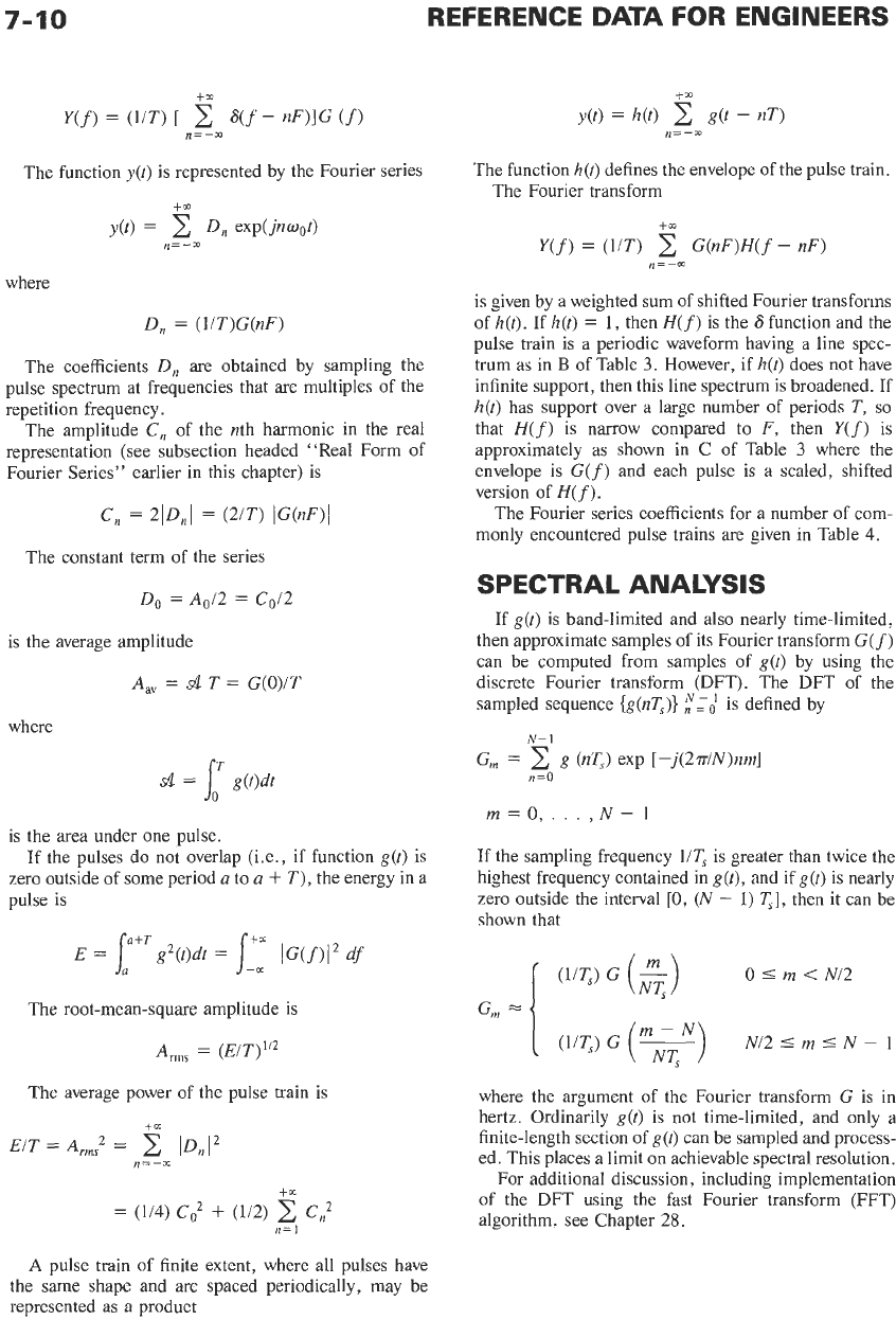
A.
Rectangular wave
Can be read
off
curve of (sinx)/.x,
A
in Table 2,
by sampling at
nsto/T
Example: If T=2f0
t
Y(~)=~AA~[%+(~/W) COS&(~/~T)
COS~O+.
‘
‘1
where 0=2.rrt/T
Derived from rectangular pulse,
A
in Table 2
AAv
=
A(t,/T)
4,,
=
A(to/T)’j2
B.
Isosceles-triangle wave
YW
f
...A
A
A..,
t
Derived from triangular pulse,
B
in Table 2
AAv
=
A(fl/T)
4,,
=
A(2t1/3T)”’
C.
Sawtooth wave
..&/I
..;
-J
0
T
2J
Derived from triangular pulse,
C
in Table 2
A,
=
Ai2
4,,
=
A(3-I”)
D.
Clipped sawtooth wave
YW
f
Example: If T=2tl
y(f)=2A~,[%+(2/77)~ Co~0+(2/3~)*
COS~O+.
’
‘1
where 0=2vt/T
C,=2AAv(1/7m)
y(f)=2AAv[%-(l/.rr) sin0-(1/2~) sin20-.
.
Derived from triangular pulse,
C
in Table 2
A,
=
A(to/2T)
A,,,
=
A(f0/3T)”*
Continued on next page.
7-12
REFERENCE
DATA
FOR ENGINEERS
TABLE
4
(CONT). PERIODIC WAVEFORMS AND FOURIER SERIES
Waveform Coefficient
of
Fourier Series
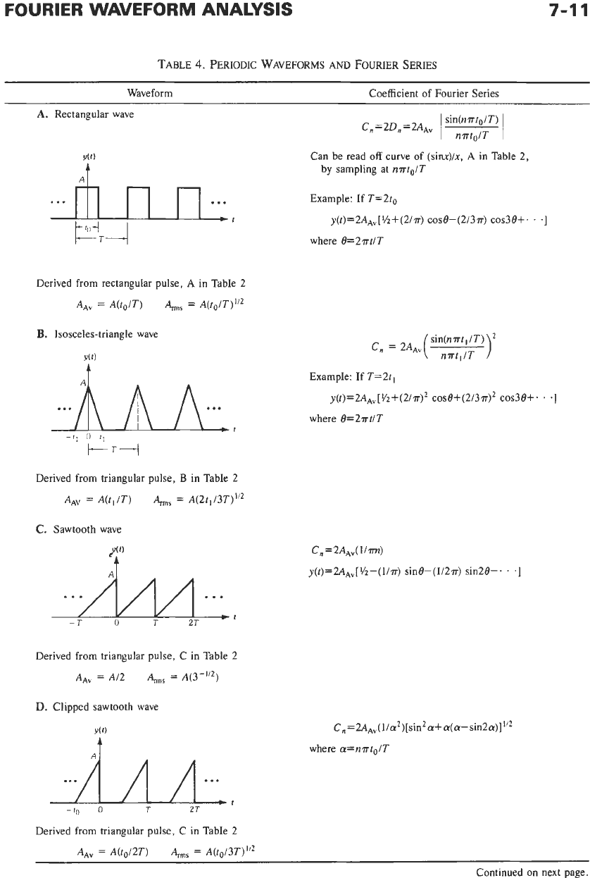
E.
Sawtooth wave
Y(t)
C,
=
2A,(T2in2n2r
I
t2)
I
sin(n.rrtl iT)
1
Derived
from
the sum
of
two triangular
pulses,
C
in Table 2
AA”
=
Ai2
A,,,
=
A(3-I”)
F.
Symmetrical trapezoidal wave
...
f
Derived as
in
D in Table 2
AA~
=
A[(ro+tl)iTl
A,,,
=
A[(3to+2t1)13T]1’2
G.
Train
of
cosine pulses
Derived from cosine pulse,
E
in
Table 2
A,
=
(2in)A(to/T)
A,,,
=
A(ro/2T)I/?
H.
Full-wave-rectified sine wave
-T/2
0
Ti2
T
t
cos(nmolT)
1
-
(2nro/~)*
C,
=
2AAv
For ntoT=1i2, this becomes nAAV/2
cO
=
2AAv
C,,
=
2AAV(4n2-1)-’, for
n#O
y(t)
=
2~,[1/2+(1/3)
COSB-(~~)
cos28+(1/35) COs38.
.
.
-(-1)n(4n2-1)-1
cosn8. .
.]
where 8
=
2miT
Derived from cosine pulse,
E
in Table 2
(same as
G
in Table
4
with
to
=
T)
AAV
=
(2i~)A
A,,
=
Ai(2”’)
Continued on next page.
FOURIER WAVEFORM
ANALYSIS
7-13
TABLE
4
(CONT).
PERIODIC WAVEFORMS AND
FOURIER
SERIES
Waveform Coefficient
of
Fourier Series
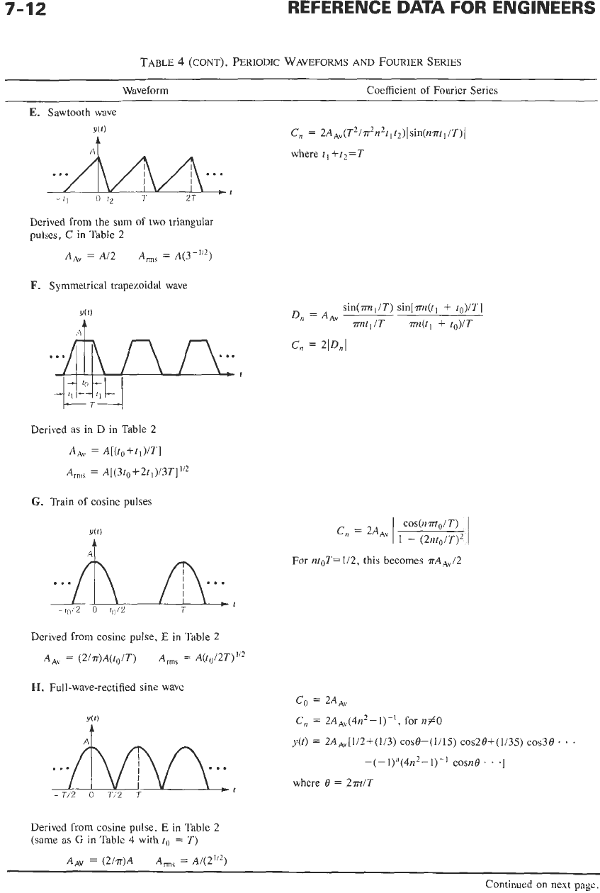
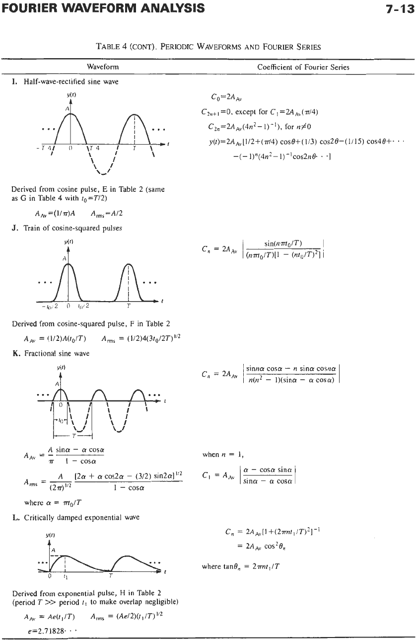
I.
Half-wave-rectified sine wave
c0=2A,
CZ~+~
=0,
except for C, =2AAv(d4)
. .
.A
,A,,
.~
Czn=2A~v(4nZ-l)-’),
for
n#O
t
y(f)=2A~~[1/2+(‘iT/4) COS@+(1/3) COS2@-(1/15) COS48+.
.
’
-T
41
0
\T
4
J
\‘
\
-(-1)n(4nZ-1)-1~~~2n@.
.
.I
\I
\I
L‘
Derive from cosine pulse,
E
in Table 2 (same
as
G
in Table 4 with t,=T/2)
I
AA,,=(l/7r)A A,,,=A/2
J.
Train
of
cosine-squared pulses
Derived from cosine-squared pulse, F
in
Table 2
A,
=
(1/2)A(ro/T)
A,,,
=
(1/2)4(3t&T)”’
K.
Fractional sine wave
i”
sinna cosa
-
n
sina
cosna:
n(n2
-
I)(sina
-
a
cosa)
C,
=
2A,
A
sina
-
a
cosa
7r
1
-
cosa
AAV
=-
whenn
=
1,
a
-
cosa sina
I
sina
-
a:
cosa
~
=
A
[2a
+
a
cos2a
-
(3/2) ~in2a]”~
1
-
COS0
Arms
=
-
(27r)”2
where
a
=
m0/T
L.
Critically damped exponential wave
Y(t)
tA
c,
=
2A,[1+(2mt,/T)*]-’
=
2~4~“
COS2@,
where tan@,
=
2imtl/T
Derived from exponential pulse,
H
in
Table 2
(period
T
>>
period
tl
to make overlap negligible)
A,,,
=
(Ae/2)(tl/T)“2
A,
=
Ae(tl/T)
e=2.71828.
. 9
8
Filters,
Simple
Bandpass
Design
Coefficient of Coupling
8-2
Gain at Resonance
8-2
Single Circuit
Pair
of
Coupled Circuits
Selectivity Far From Resonance
8-3
For Inductive Coupling
For Capacitive Coupling
Selectivity
of
Single- and Double-Tuned Circuits Near
Resonance
8-3
Selectivity and Phase Shift of Single-Tuned Circuits
Q
Determination by 3-Decibel Points
Selectivity and Phase Shift
of
Pairs
of
Coupled Tuned Circuits
Node Input Impedance or Mesh Input Admittance
of
a Double-Tuned
Circuit
8-10
8-
1
8-2
REFERENCE DATA FOR ENGINEERS
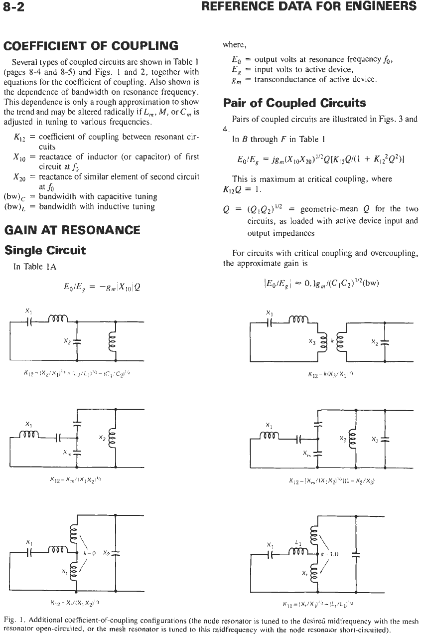
COEFFICIENT
OF
COUPLING
where,
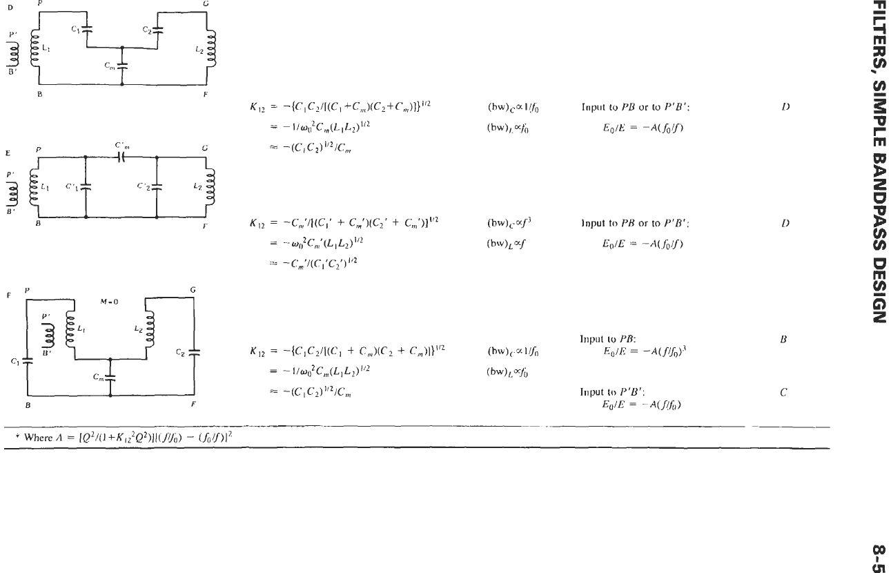
Several types of coupled circuits are shown in Table
1
(pages
8-4
and
8-5)
and Figs.
1
and
2,
together with
equations for the coefficient of coupling.
Also
shown is
the dependence of bandwidth on resonance frequency.
This dependence
is
only a rough approximation to show
the trend and may be altered radically if
L,,
M,
or
C,
is
adjusted in tuning to various frequencies.
Eo
=
output volts at resonance frequencyfo,
E,
=
input volts to active device,
g,
=
transconductance of active device.
Pair
of
Coupled Circuits
4
Pairs of coupled circuits are illustrated in Figs.
3
and
K12
=
coefficient of coupling between resonant cir-
XI,
=
reactance of inductor (or capacitor)
of
first
XzO
=
reactance
of
similar element of second circuit
cuits
circuit atfo
at
fo
(bw),
=
bandwidth with capacitive tuning
(bw),
=
bandwidth with inductive tuning
GAIN AT RESONANCE
Single Circuit
In Table
1A
In
B
through
F
in Table
I
Eo/Eg
=
jgm(XIOX20)1’2Q[K1,Q/(l
+
K1?Q2)1
This is maximum at critical coupling, where
Kl,Q
=
1.
Q
=
(QiQd”’
=
geometric-mean
Q
for the two
circuits, as loaded with active device input and
output impedances
For circuits with critical coupling and overcoupling,
the approximate gain
is
1
Eo/E,
1
=
0.
lg
,/(C
C,)
”2(bw)
K12=
x,/(xIxpl’
*
KI2=
(X,/X,)I’Z=
(Lt/LlIl’Z
Fig.
1
,
Additional coefficient-of-coupling configurations (the node resonator
is
tuned to the desired midfrequency with the mesh
resonator open-circuited, or the mesh resonator
is
tuned to this midfrequency with the node resonator short-circuited).
FILTERS, SIMPLE BANDPASS DESIGN
8-3
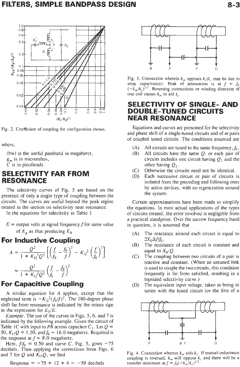
(X,/X2)”2
Fig. 2. Coefficient
of
coupling
for
configuration shown.
where,
(bw) is the useful passband in megahertz,
g,
is in micromhos,
C
is in picofarads.
SELECTIVITY FAR FROM
RESONANCE
The selectivity curves of Fig.
5
are based on the
presence of only a single type of coupling between the
circuits. The curves are useful beyond the peak region
treated in the section on selectivity near resonance.
In the equations for selectivity in Table
1
E
=
output volts at signal frequency
f
for same value
of
E,
as that producing
Eo
For Inductive Coupling
Q2
(Lb)
2
=s
1
f
Kn2Q2
fo
f
For Capacitive Coupling
A
similar equation for
A
applies, except that the
neglected term is
-K$(fOif)*.
The 180-degree phase
shift far from resonance is indicated by the minus sign
in
the expression for
EoIE.
Example.
The use
of
the curves in Figs.
5,6,
and
7
is
indicated by the following example. Given the circuit
of
Table
1C
with input to
PB
across capacitor
C1
.
Let
Q
=
50,
K,,Q
=
1
SO,
andfo
=
16.0
megahertz. Required is
the response at
f
=
8.0 megahertz.
Here,
ffo
=
0.50
and curve
C,
Fig.
5,
gives
-75
decibels. Then applying the corrections from Figs.
6
and
7
for
Q
and
K,,Q,
we find
Response
=
-75
+
12
+
4
=
-59
decibels
r7+&l
P
F
Fig.
3.
Connection wherein
k,
opposes
k,(k,
may
be
due to
stray capacitance). Peak of attenuation is at
f
=
fo
(-k,/kc)”l.
Reversing connections
or
winding direction
of
one
coil causes
k,
to
aid
k,.
SELECTIVITY OF SINGLE- AND
DOUBLE-TUNED CIRCUITS
NEAR RESONANCE
Equations and curves are presented for the selectivity
and phase shift of
n
single-tuned circuits and of
m
pairs
of coupled tuned circuits. The conditions assumed are
All circuits are tuned to the same frequency,&.
All circuits have the same
Q,
or each pair of
circuits includes one circuit having
Q,
and the
other having
Q2.
Otherwise the circuits need not be identical.
Each successive circuit or pair
of
circuits
is
isolated from the preceding and following ones
by active devices, with no regeneration around
the system.
Certain approximations have been made to simplify
the equations. In most actual applications of the types
of circuits treated, the error involved is negligible from
a practical standpoint. Over the narrow frequency band
in question, it is assumed that
The reactance around each circuit is equal to
The resistance of each circuit is constant and
equal to
Xo/Q.
The coupling between two circuits of
a
pair is
reactive and constant. (When an untuned link
is used to couple the two circuits, this condition
frequently is far from satisfied, resulting in
a
lopsided selectivity curve.)
The equivalent input voltage, taken as being in
series with the tuned circuit (or the first of a
(A)
(B)
(C)
(D)
(A)
(B)
(C)
2XOAfifo.
(D)
P BF
G
Fig.
4.
Connection wherein
k,
aids
k,.
If
mutual-inductance
coupling is reversed,
k,
will oppose
k,
and there will
be
a
transfer minimum atf
=
fo(-k,/k,)’!*.
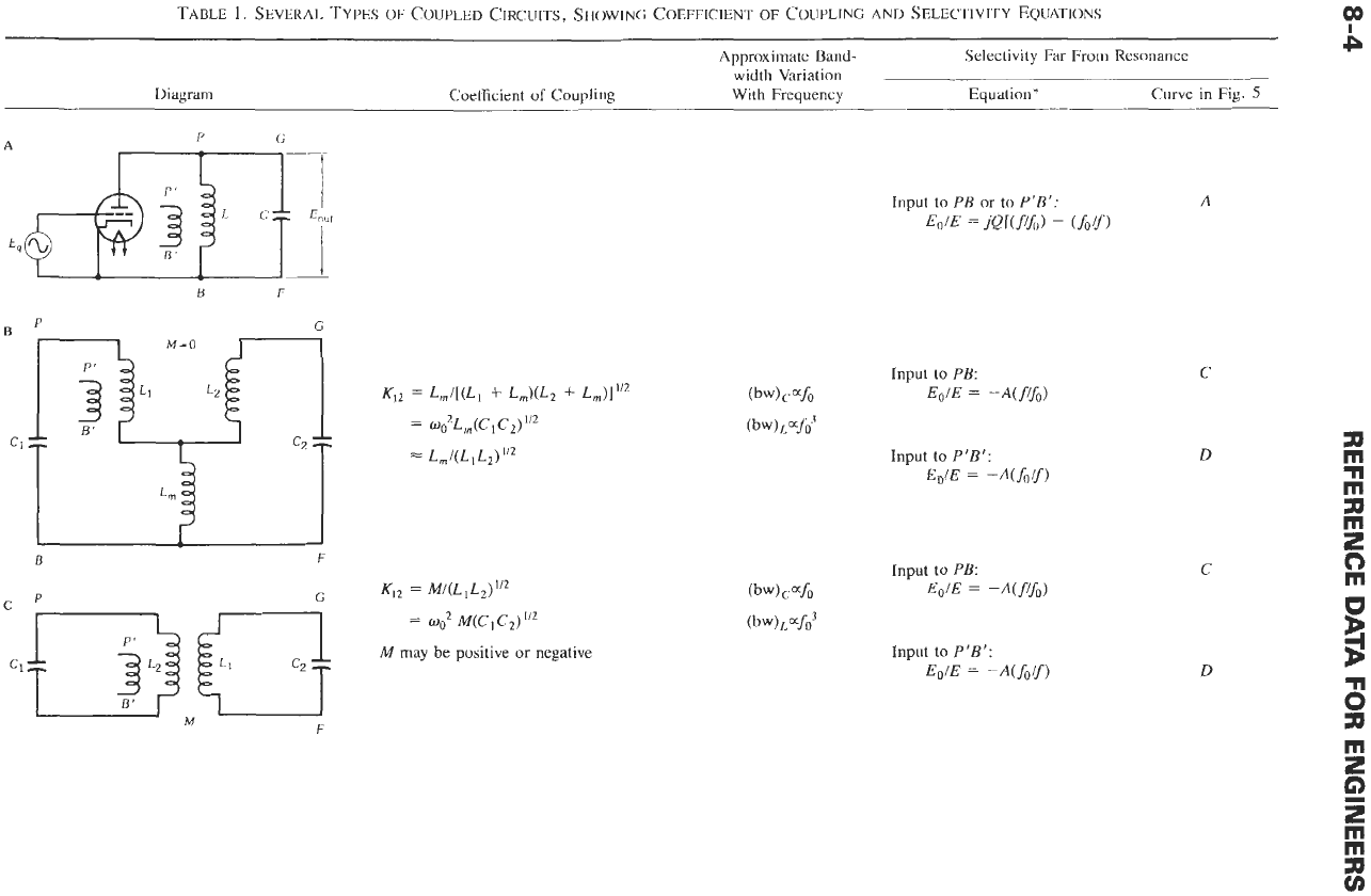
TABLE
1.
SEVERAL TYPES
OF
COUPLED CIRCUITS,
SliOWlNG
COEFFICIENT
OF
COUPLING
AND
SELEcllVlTY EQUATIONS
00
Approximate Band-
width Variation
Diagram Coefficient
of
Coupling With Frequency
Selectivity
Far
From
Resonance
Equalion*
Curve in Fig.
5
B
F
=
0:
M(C,C,)”Z
c1
ITL)
M
may be positive
or
negative
M
F
Input to
PR
or
to
P
’B’:
A
EdE
=
jQKf!!)
-
(SOY)
C
D
P
G
D
B
F
E
P'
wc-
F
CI
1
cz
T
B
F
Input
to
PB
or
to
P'B':
EOIE
=
-A(fo/f)
Input
to
PB:
EOIE
=
-A(f/fo)'
Input to
P'B':
EOIE
=
-A(fl&)
D
in
m
b
D
B
C
2
0
v)
v)
0
m
VJ
2
9
nl