Middleton W.M. (ed.) Reference Data for Engineers: Radio, Electronics, Computer and Communications
Подождите немного. Документ загружается.

8-6
REFERENCE
DATA
FOR
ENGINEERS
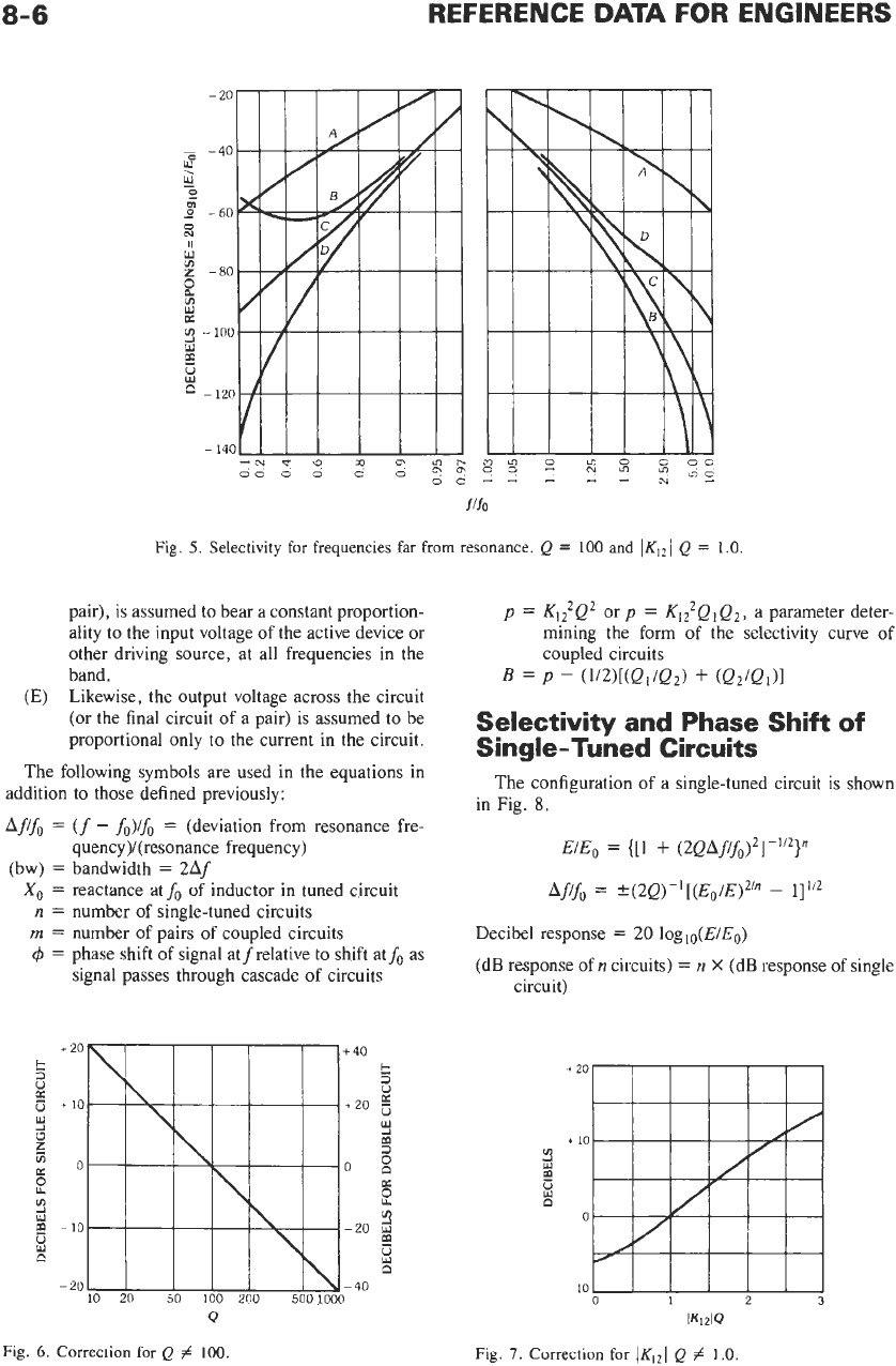
Fig.
5.
Selectivity
for
frequencies far from resonance.
Q
=
100
and
IKI2/
Q
=
1.0.
pair), is assumed to bear a constant proportion-
ality to the input voltage of the active device or
other driving source, at all frequencies in the
band.
Likewise, the output voltage across the circuit
(or the final circuit
of
a
pair) is assumed to be
proportional only to the current in the circuit.
The following symbols are used in the equations in
addition to those defined previously:
Aff,
=
(f
-
fo)fo
=
(deviation from resonance fre-
(bw)
=
bandwidth
=
2Af
(E)
quency)/(resonance frequency)
X,
=
reactance atfo of inductor in tuned circuit
n
=
number of single-tuned circuits
m
=
number of pairs of coupled circuits
4
=
phase shift of signal atfrelative to shift atfo
as
signal passes through cascade of circuits
Q
Fig.
6.
Correction
for
Q
#
100.
p
=
K12Q2
or
p
=
K12QIQ2,
a parameter deter-
mining the form of the selectivity curve of
coupled circuits
B
=
P
-
(W[(Qi/Qd
+
(9219i)I
Selectivity and Phase Shift of
Single-Tuned Circuits
The configuration of a single-tuned circuit is shown
in Fig.
8.
E/E,
=
{[1
+
(2QAf/fo)2]-i’2}n
Aflf,
=
?(2Q)-i[(Eo/E)2’fl
-
11”’
Decibel response
=
20
loglo(E/Eo)
(dB response of
n
circuits)
=
n
X
(dB response of single
circuit)
-t
4
Y
m
i
20
.
10
0
10
0
1 2
3
IKizIQ
Fig. 7.
Correction
for
lKI21
Q
#
1.0.
FILTERS, SIMPLE BANDPASS DESIGN
8-7
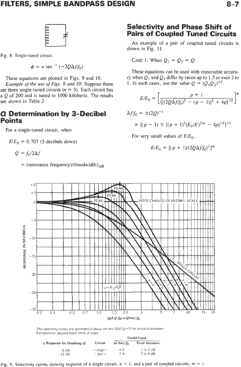
Fig.
8.
Single-tuned circuit.
4
=
n
tan-’
(-2QAfifo)
These equations are plotted in Figs.
9
and
IO.
Example
of
the use
of
Figs.
9
and
IO:
Suppose there
are three single-tuned circuits
(n
=
3).
Each circuit has
a
Q
of
200
and
is
tuned to
1000
kilohertz. The results
are shown in Table
2.
0
Determination
by
3-Decibel
Points
For a single-tuned circuit, when
EIE,
=
0.707 (3
decibels down)
Q
=hWf
=
(resonance
frequency)/(bandwidth)3dB
Selectivity and Phase Shift
of
Pairs of Coupled Tuned Circuits
An example
of
a pair
of
coupled tuned circuits is
shown in Fig.
11.
CASE
1: When
Ql
=
Q2
=
Q:
These equations can be used with reasonable accura-
cy when
Q
and
Q2
differ by ratios up to
1.5
or even
2
to
1.
In such cases, use the value
Q
=
(Q
I
Q2)
Afifo
=
?(2Q)-’
X
{(p
-
1)
t
[(p
+
1)2(Eo/E)2’m
-
4~]’’~}’’’
For very small values
of
EIE,;
EIEo
=
[(P
+
1)/(2QAfifo)21m
The
selectivity
curves are
symmetrical about
the
axis
Q4iiiio
=
0
for
practical
purposes
Extrapolation beyond
lower
limits
of
chart.
Useful
Limit
A
Response
for
Doubling
Af
Circuit
at
(bw)/fg
Error
becomes
-6
dB
-single-
0
6
1
to
2
dB
-
12
dB
-pair-
0
4
3
to
4
dB
Fig.
9.
Selectivity curves showing response
of a
single circuit,
n
=
1,
and
a
pair
of
coupled circuits,
rn
=
1.
8-8
0
-
20
v)
y
-40
K
s
c)
-60
z
3
a
W
-80
;
-100
E
-120
2
$
-140
ci
a
m
U
W
-
160
-
180
002
06
10152253
4
5
6
7
8
Q(U/Jo)
=
QU-fo)/fo
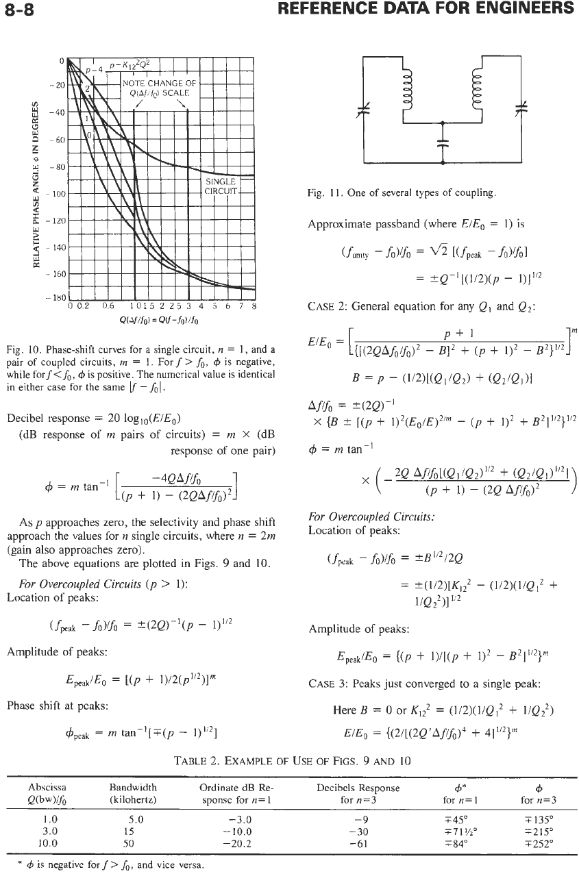
Fig.
10.
Phase-shift curves for a single circuit,
n
=
1,
and a
pair
of
coupled circuits,
m
=
1.
For
f
>
fo,
Cp
is negative,
while fort<&,
4
is positive. The numerical value is identical
in either case
for
the same
-
fo
1.
Decibel response
=
20
loglo(E/Eo)
(dB response of
rn
pairs of circuits)
=
rn
X
(dB
response of one pair)
As
p
approaches zero, the selectivity and phase shift
approach the values for
n
single circuits, where
n
=
2rn
(gain also approaches zero).
The above equations are plotted in Figs.
9
and
10.
For Overcoupled Circuits (p
>
1):
Location of peaks:
Amplitude of peaks:
Phase shift at peaks:
Fig.
1
1.
One
of
several types
of
coupling
Approximate passband (where
E/Eo
=
1)
is
CASE
2:
General equation for any
Ql
and
Q2:
P+l
E'Eo
=
[{[(2QAfo!fo)2
-
BI2
+
(p
+
1)2
-
B2}"*
B
=
P
-
(W[(Qi/Q2)
+
(Q21Qi)I
Afifo
=
+(2Q)-'
x
{B
?
[(p
+
i)2(~,/~)2/m
-
(p
+
i)2
+
~~1~/~)~/~
4
=
rn
tan-'
+
(Q2/Q1)"21)
(-2Q Afifo[(Q1/Q2)'/~
(p
+
1)
-
(2Q
Aflfol2
For Overcoupled Circuits:
Location of peaks:
(fpeak
-
f0)ifo
=
*B''2/2Q
=
+(1/2)[Kl;
-
(1/2)(1/Q12
t
1/Q;)]"2
Amplitude of peaks:
Epea!JEo
=
{(p
+
l)/[(p
+
112
-
B21"2}M
CASE
3:
Peaks
just
converged
to
a single
peak:
Here
B
=
0
or
Kl?
=
(1/2)(1/(21*
+
1/Q;)
EIE,
=
{(21[(2~'~f/fo)4
+
411/2}m
TABLE
2.
EXAMPLE
OF
USE
OF
FIGS.
9
AND
10
Abscissa Bandwidth Ordinate dB
Re-
Decibels Response
P
4
Q(bw)lf, (kilohertz)
sponse for
n=
1
for
n=3
for
n=
1
for
n=3
1
.o
5.0
-3.0
3.0
15
-
10.0
10.0
50
-20.2
-9
i45"
i
135"
-30
771
%"
T215"
-61
T
84" T252"
*
4
is negative
forf
>
fo,
and vice versa
FILTERS, SIMPLE BANDPASS DESIGN
10
09
08
!A
V
5
07
c
06
c
2
05
0
%
04
5
03
E:
z
a
2
-
02
01
0
-
8-9
-14
-10
-06
-02
0
02
06
10
14
(W/Vo/Qz)
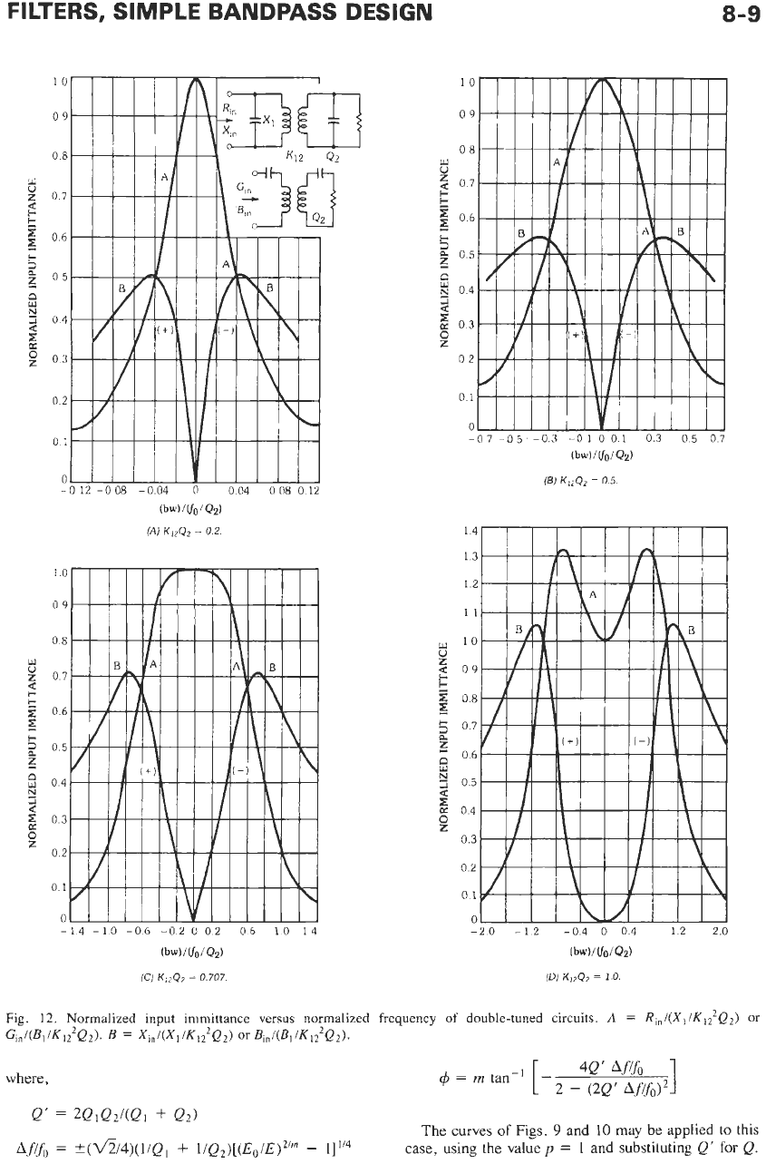
(C)
Ki2Q2
=
0.707
Fig. 12. Normalized input immittance versus normalized frequency of double-tuned circuits.
A
=
R,,/(X, /K,?Q2)
or
G,,i(BliKl,2Q2).
B
=
X,nI(X~/K~?Qd
or
B,,I(BIKI?Qz).
where,
4Q’
1
4
=
m
tan-’
[
-
2
-
(2Q’
Afifo)’
Q’
=
2QiQz/(Qi
+
Q2)
The curves
of
Figs.
9
and
10
may be
applied
to this
case, using the value
p
=
1
and
substituting
Q‘
for
Q.
~fifo
=
*~‘54)(i/~,
+
I~Q~)[(E~/E)~/~
-
1i1l4
8-10
REFERENCE DATA
FOR
ENGINEERS
NODE INPUT IMPEDANCE
OR
MESH INPUT ADMITTANCE
OF
A DOUBLE-TUNED CIRCUIT
the normalized frequency
of
double-tuned circuits.
Fig.
12
gives the normalized input immittance versus
9
Filters,
Modern-Network-
Theory Design
Ford Shepherd
Introduction
9-2
Normalization
9-2
The Reference Low-Pass
9-3
Cauer-Parameter Low-Pass Filters
9-4
Chebyshev Low-Pass Filters
9-14
Butterworth Low-Pass Filters
9-14
Low-Pass to High-Pass Transformation
9-14
Low-Pass
to
Bandpass Transformation
9-14
Low-Pass to Band-Stop Transformation
9-19
Numerical Examples
9-19
9-
1
9-2
In contrast to filter design by image-parameter meth-
ods, the design of filters by the use
of
modern network
theory is a domain for specialists with digital computers
because of the complex calculations required. There are
sufficient advantages of filter circuits computed by this
method, however, to warrant making some application
of them easy and straightforward. This chapter focuses
on a very limited subset of the limitless possibilities for
low-pass networks and simple transform methods to
allow calculation of high-pass, bandpass, and band-stop
circuits.
The design information is drawn from experience in
the application of modern network theory to the design
of electric wave filters.
As
stated above, only limited
design results are supplied, and a concentrated study of
the cited references
is
essential to gain a working
knowledge of the synthesis process through which these
results were computed. References
1,
4,
and
6
provide
details of the design theory. Reference
5
provides a
concise summary of the theory with graphs and tables
to enable an engineer to compute filter circuits with the
help of a computer program.
Reference
2
provides a much larger tabulation of
Cauer-parameter and Chebyshev filter networks up to
degree
9,
and Saal has also produced another volume
that extends to degree
15.
Reference 3 presents many
practical ideas (drawn from a 25-year career in Europe
and the
USA)
on designing, testing, and manufacturing
filters and mentions two of the computer programs that
are available. Many books and articles written on this
subject since the work of Cauer and Darlington in the
late 1930s are more than worthy of mention here.
However, the scope of this chapter and the space
available do not necessitate nor permit a detailed
discussion. Reference
7
is an example of some of the
work done toward practical implementation of these
filter networks with standard-value capacitors.
No
attempt has been made to present details of the
theory and formulation involved, of the approximation
of transfer polynomials to performance requirements,
or the very useful but less frequently required topics
such as zero and infinite terminations, phase and delay
performance, and the effects of and compensation for
the losses in real coils and capacitors.
INTRODUCTION
Filter networks continue to be of great importance in
the design of electrical equipment, especially in com-
munication engineering. Unlike previous methodolo-
gies to design spectrum-shaping networks, modern
network theory enables the engineer
to
design filter
networks that are based on the actual requirements for
signal transmission. While image-parameter design
is
rather simplistic, only a very limited approximation of
the specific requirements can be achieved. Today’s
methods are not
so
straightforward and are generally
considered beyond the scope of nonspecialists, since the
mathematical design process does not directly parallel
physical conceptions and the calculations are complex
and extensive. The development of digital computers
has led to the capture of much of the knowledge of the
specialist and the complex calculation algorithms into
programs that allow many engineers to design some of
their own networks. Still, the sophisticated require-
ments necessitate the special expert.
Many of the less complex requirements can be
satisfied by designs that can be done with the
procedures described here and without access to the
computer programs. To accomplish this task, the re-
quirements for all the filter types considered here
(low-pass, high-pass, bandpass and band-stop) are
transformed to a set of reference low-pass requirements.
From the reference low-pass requirements, the network
complexity is determined, and a normalized reference
low-pass
is
selected. Then the suitable transformation
is
applied to this low-pass to arrive at the network to
satisfy the initial requirements.
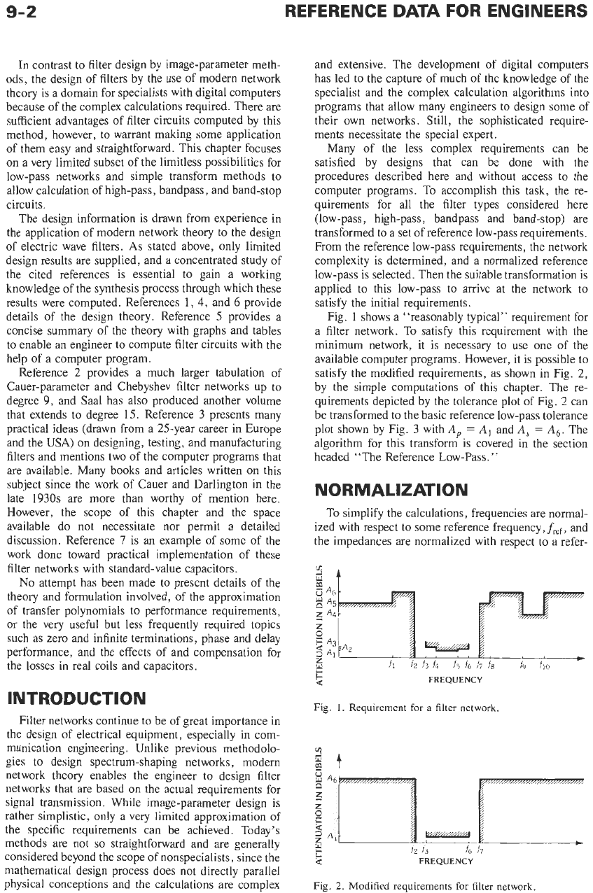
Fig.
1
shows a “reasonably typical” requirement for
a filter network. To satisfy this requirement with the
minimum network, it is necessary to use one
of
the
available computer programs. However, it is possible to
satisfy the modified requirements, as shown in Fig.
2,
by the simple computations of this chapter. The re-
quirements depicted by the tolerance plot of Fig.
2
can
be transformed to the basic reference low-pass tolerance
plot shown by Fig.
3
with
A,
=
AI
and
A,
=
A,.
The
algorithm for this transform is covered in the section
headed “The Reference Low-Pass.”
NORMALIZATION
To simplify the calculations, frequencies are normal-
ized with respect to some reference frequency,fref, and
the impedances are normalized with respect to a refer-
FREQUENCY
Fig.
1.
Requirement for
a
filter network.
Fig.
2.
Modified requirements for filter network
FILTERS, MODERN-NETWORK-THEORY DESIGN
Y
n
2
FREQUENCY
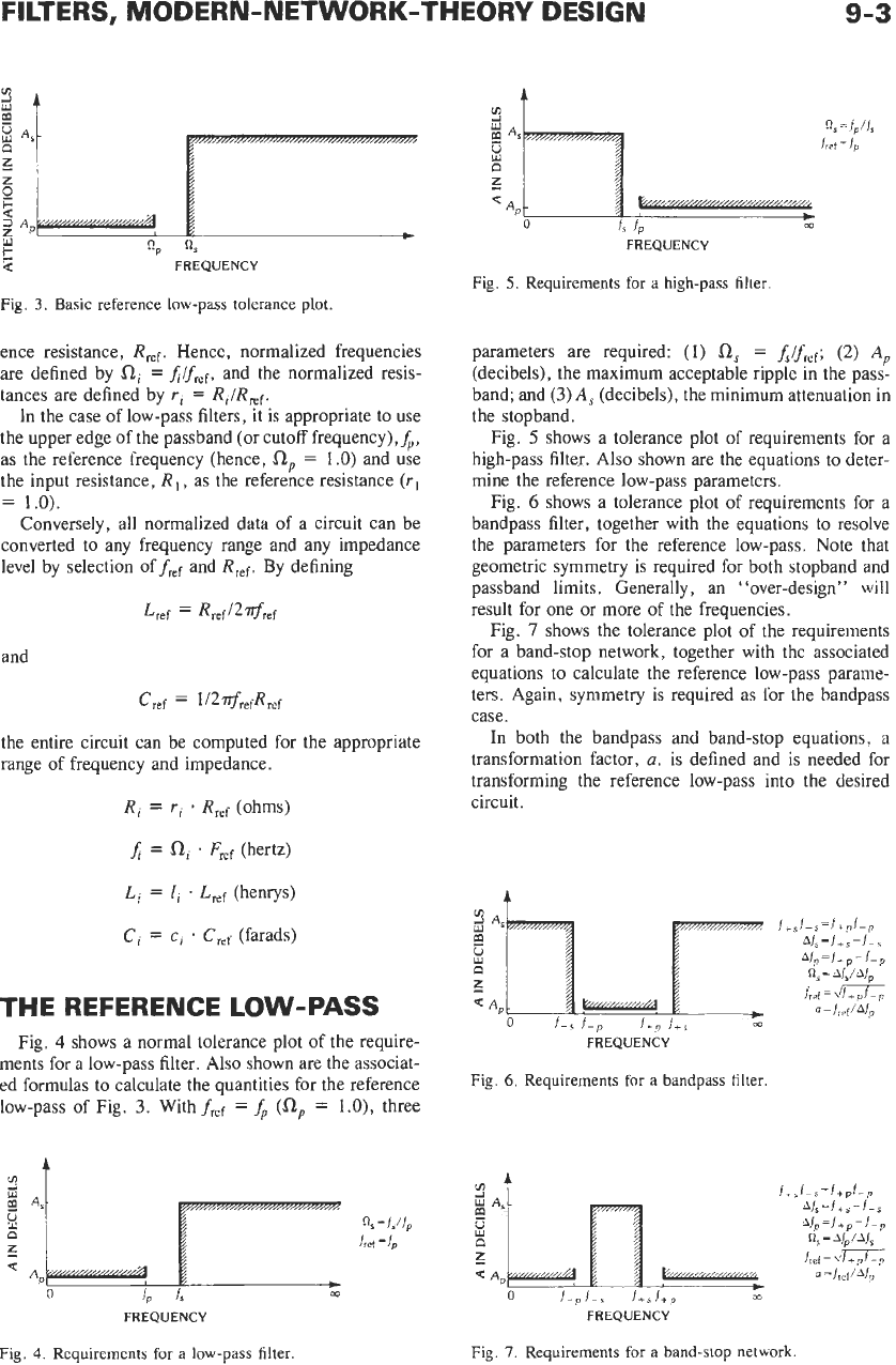
Fig.
3.
Basic reference low-pass tolerance plot.
ence resistance,
Rref.
Hence, normalized frequencies
are defined by
Ri
=
J/fer,
and the normalized resis-
tances are defined by
rl
=
Ri/Rref.
In the case of low-pass filters, it is appropriate to use
the upper edge of the passband (or cutoff frequency),&,
as the reference frequency (hence,
Rp
=
1
.O)
and use
the input resistance,
R,
,
as the reference resistance
(Il
=
1.0).
Conversely, all normalized data of a circuit can be
converted to any frequency range and any impedance
level by selection of
fief
and
Rref.
By defining
and
Cref
=
1/2$refRref
the entire circuit can be computed for the appropriate
range of frequency and impedance.
Ri
=
ri
*
Rref
(ohms)
J
=
Ri
1
Fref
(hertz)
Li
=
li
.
Lref
(henrys)
Ci
=
ci
.
Cref
(farads)
THE REFERENCE
LOW-PASS
Fig.
4
shows a normal tolerance plot of the require-
ments for a low-pass filter. Also shown are the associat-
ed formulas to calculate the quantities for the reference
low-pass of Fig.
3.
Withf,,,
=
&
(a,
=
l.O),
three
0
1,
fs
co
FREQUENCY
Fig.
4.
Requirements for a low-pass filter.
VI
t
9-3
FREQUENCY
Fig.
5.
Requirements for
a
high-pass filter.
parameters are required:
(1)
0,
=
if,,,;
(2)
A,
(decibels), the maximum acceptable ripple in the pass-
band; and
(3)
A,
(decibels), the minimum attenuation in
the stopband.
Fig.
5
shows a tolerance plot of requirements for a
high-pass filter. Also shown are the equations to deter-
mine the reference low-pass parameters.
Fig.
6
shows a tolerance plot of requirements for a
bandpass filter, together with the equations to resolve
the parameters for the reference low-pass. Note that
geometric symmetry
is
required for both stopband and
passband limits. Generally, an "over-design" will
result for one or more of the frequencies.
Fig.
7
shows the tolerance plot of the requirements
for a band-stop network, together with the associated
equations to calculate the reference low-pass parame-
ters. Again, symmetry is required as for the bandpass
case.
In both the bandpass and band-stop equations, a
transformation factor,
a,
is defined and is needed for
transforming the reference low-pass into the desired
circuit.
4
FREQUENCY
Fig. 6. Requirements
for
a bandpass filter.
____c
0
f-pf-s
f+sf+,
m
FREQUENCY
Fig.
7.
Requirements for a band-stop network
9-4
REFERENCE
DATA
FOR ENGINEERS
CAUER- PARAMETER
LOW-
PASS
FILTERS
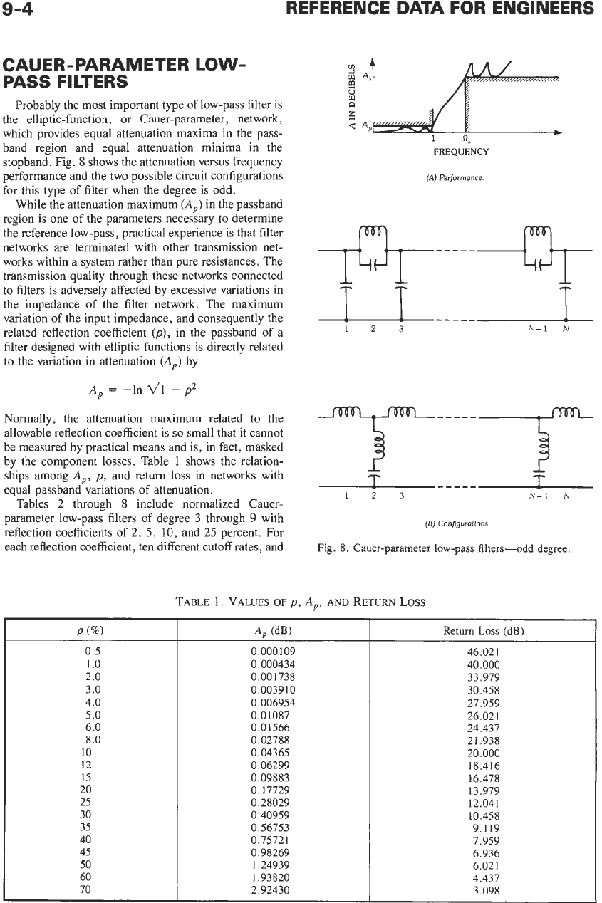
Probably the most important type of low-pass filter is
the elliptic-function, or Cauer-parameter, network,
which provides equal attenuation maxima in the pass-
band region and equal attenuation minima in the
stopband. Fig.
8
shows the attenuation versus frequency
performance and the two possible circuit configurations
for this type of filter when the degree is odd.
While the attenuation maximum
(A,)
in the passband
region
is
one of the parameters necessary to determine
the reference low-pass, practical experience is that filter
networks are terminated with other transmission net-
works within a system rather than pure resistances. The
transmission quality through these networks connected
to filters is adversely affected by excessive variations in
the impedance of the filter network. The maximum
variation
of
the input impedance, and consequently the
related reflection coefficient
(p),
in the passband of a
filter designed with elliptic functions
is
directly related
to
the variation in attenuation
(A,)
by
A,
=
-In-
Normally, the attenuation maximum related to the
allowable reflection coefficient is
so
small that it cannot
be measured by practical means and is, in fact, masked
by the component losses. Table
1
shows the relation-
ships among
A,,
p.,
and return loss in networks with
equal passband variations of attenuation.
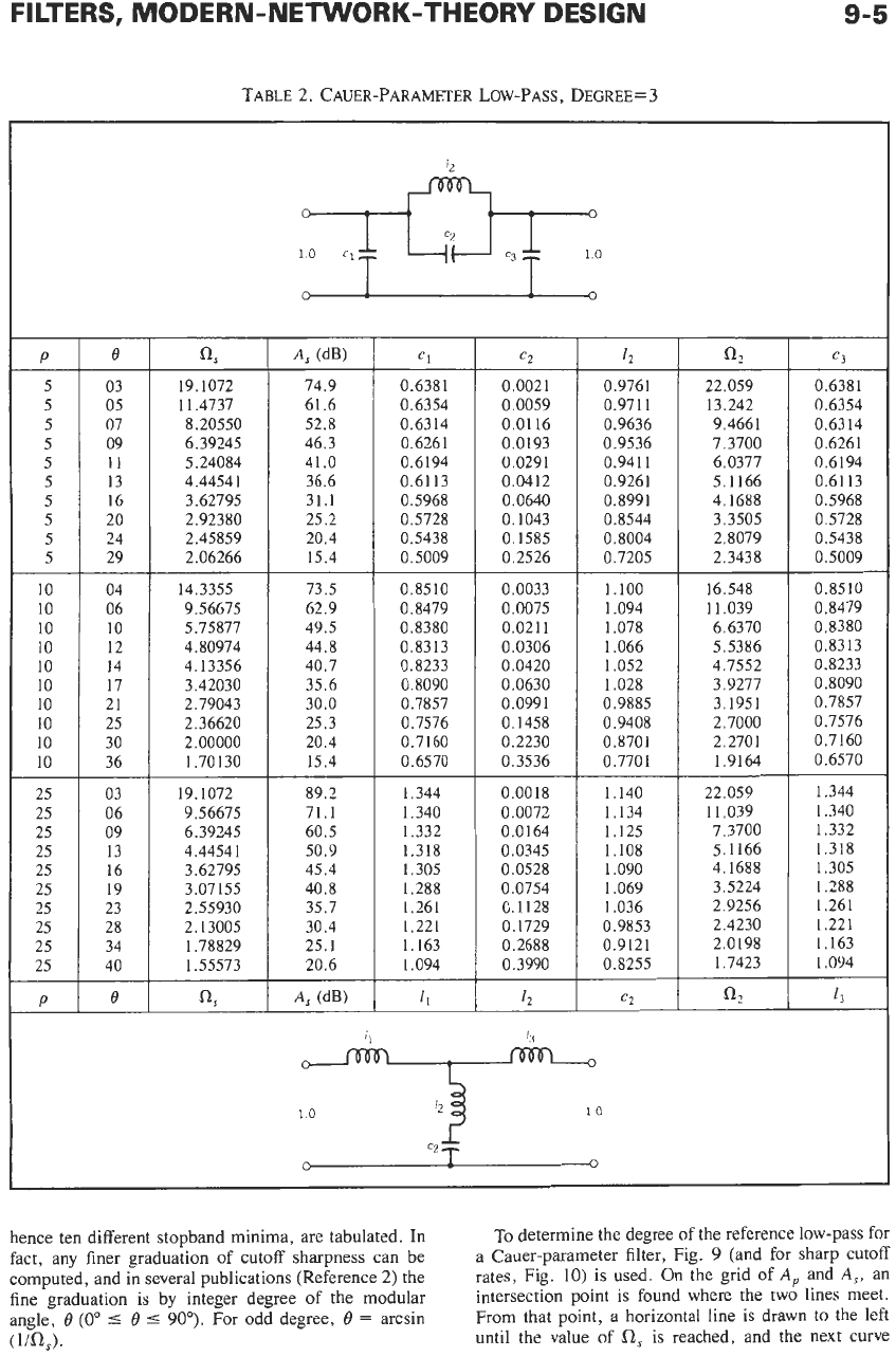
Tables
2
through
8
include normalized Cauer-
parameter low-pass filters of degree
3
through
9
with
reflection coefficients of
2,
5,
10,
and
25
percent. For
each reflection coefficient, ten different cutoff rates, and
FREQUENCY
(A)
Performance
N-1
N
123
(5)
Configurations
Fig. 8.
Cauer-parameter low-pass filters-odd degree,
TABLE
1.
VALUES
OF
p,
A,,
AND
RETURN
LOSS
P
(8)
0.5
1
.o
2.0
3.0
4.0
5.0
6.0
8.0
10
12
15
20
25
30
35
40
45
50
60
70
A,
(dB)
0,000
109
0.000434
0.001738
0.0039 10
0.006954
0.01087
0.01 566
0.02788
0.04365
0.06299
0.09883
0.17729
0.28029
0.40959
0.56753
0.75721
0.98269
1.24939
1.93820
2.92430
Return
Loss
(dB)
46.021
40.000
33.979
30.458
27.959
26.021
24.437
21.938
20.000
18.416
16.478
13.979
12.041
10.458
9.119
7,959
6.936
6.021
4.437
3.098
FILTERS, MODERN-NETWORK-THEORY DESIGN
19.1072
9.56675
6.39245
4.44541
3.62795
3.07155
2.55930
2.13005
1.78829
1.55573
89.2
71.1
60.5
50.9
45.4
40.8
35.7
30.4
25.1
20.6
TABLE
2.
CAUER-PARAMETER LOW-PASS, DEGREE=
3
P
5
5
5
5
5
5
5
5
5
5
-
c2
c3
a,
19.1072
11.4737
8.20550
6.39245
5.24084
4.44541
3.62795
2.92380
2.45859
2.06266
14.3355
9.56675
5.75877
4.80974
4.13356
3.42030
2.79043
2.36620
2
.ooooo
1.70130
e
03
05
07
09
11
13
16
20
24
29
04
06
10
12
14
17
21
25
30
36
A,
(dB)
74.9
61.6
52.8
46.3
41.0
36.6
31.1
25.2
20.4
15.4
12
0.9761
0.971 1
0.9636
0.9536
0.941 1
0.9261
0.8991
0.8544
0.8004
0.7205
1.100
1.094
1.078
1.066
1.052
1.028
0.9885
0.9408
0.8701
0.7701
1.140
1.134
1,125
1.108
1.090
1.069
1.036
0.9853
0.9121
0.8255
c2
Cl
0.6381
0.6354
0.6314
0.6261
0.6194
0.6113
0.5968
0.5728
0.5438
0.5009
0.0021
0.0059
0.01
16
0.0193
0.0291
0.0412
0.0640
0.1043
0.1585
0.2526
22.059
13.242
9.4661
7.3700
6.0377
5.1166
4.1688
3.3505
2.8079
2.3438
0.6381
0.6354
0.6314
0.6261
0.6194
0.61 13
0.5968
0.5728
0.5438
0.5009
10
10
10
10
10
10
10
10
10
10
73.5
62.9
49.5
44.8
40.7
35.6
30.0
25.3
20.4
15.4
0.8510
0.8479
0.8380
0.8313
0.8233
0.8090
0.7857
0.7576
0.7160
0.6570
0.0033
0.0075
0.0211
0.0306
0.0420
0.0630
0.0991
0.1458
0.2230
0.3536
16.548
11.039
6.6370
5.5386
4.7552
3.9277
3.1951
2.7000
2.2701
1.9164
0.8510
0.8479
0.8380
0.8313
0.8233
0.8090
0.7857
0.7576
0.7160
0.6570
25
25
25
25
25
25
25
25
25
25
03
06
09
13
16
19
23
28
34
40
1.344
1.340
1.332
1.318
1.305
1.288
1.261
1.221
1.163
1.094
0.0018
0.0072
0.0164
0.0345
0.0528
0.0754
0.1128
0.1729
0.2688
0.3990
22.059
11.039
7.3700
5.1166
4.1688
3.5224
2.9256
2.4230
2.0198
1.7423
1.344
1.340
1.332
1.318
1.305
1.288
1.261
1.221
1.163
1.094
P
e
13
1.0
c2
0
0
hence ten different stopband minima, are tabulated.
In
fact, any finer graduation of cutoff sharpness can be
computed, and in several publications (Reference
2)
the
fine graduation is by integer degree
of
the modular
angle,
0
(0"
5
0
5
90").
For odd degree,
0
=
arcsin
(1i0,).
To
determine the degree
of
the reference low-pass for
a Cauer-parameter filter, Fig.
9
(and for sharp cutoff
rates, Fig.
10)
is used. On the grid
of
A,
and
A,,
an
intersection point
is
found where the two lines meet.
From that point, a horizontal line is drawn
to
the left
until the value of
a,
is reached, and the next curve