Middleton W.M. (ed.) Reference Data for Engineers: Radio, Electronics, Computer and Communications
Подождите немного. Документ загружается.

9-16
REFERENCE
DATA
FOR ENGINEERS
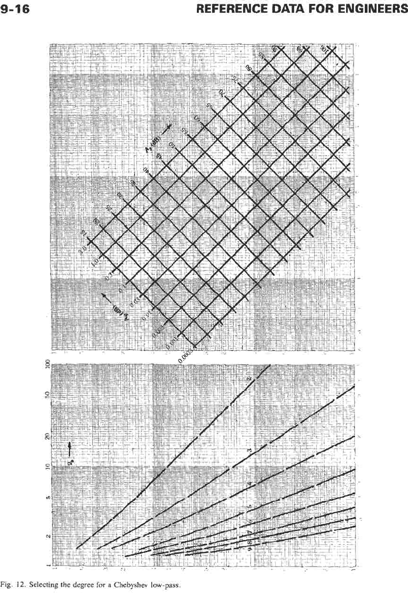
Fig.
12.
Selecting
the
degree
for
a
Chebyshev low-pass
FILTERS, MODERN-NETWORK-THEORY DESIGN
9-17
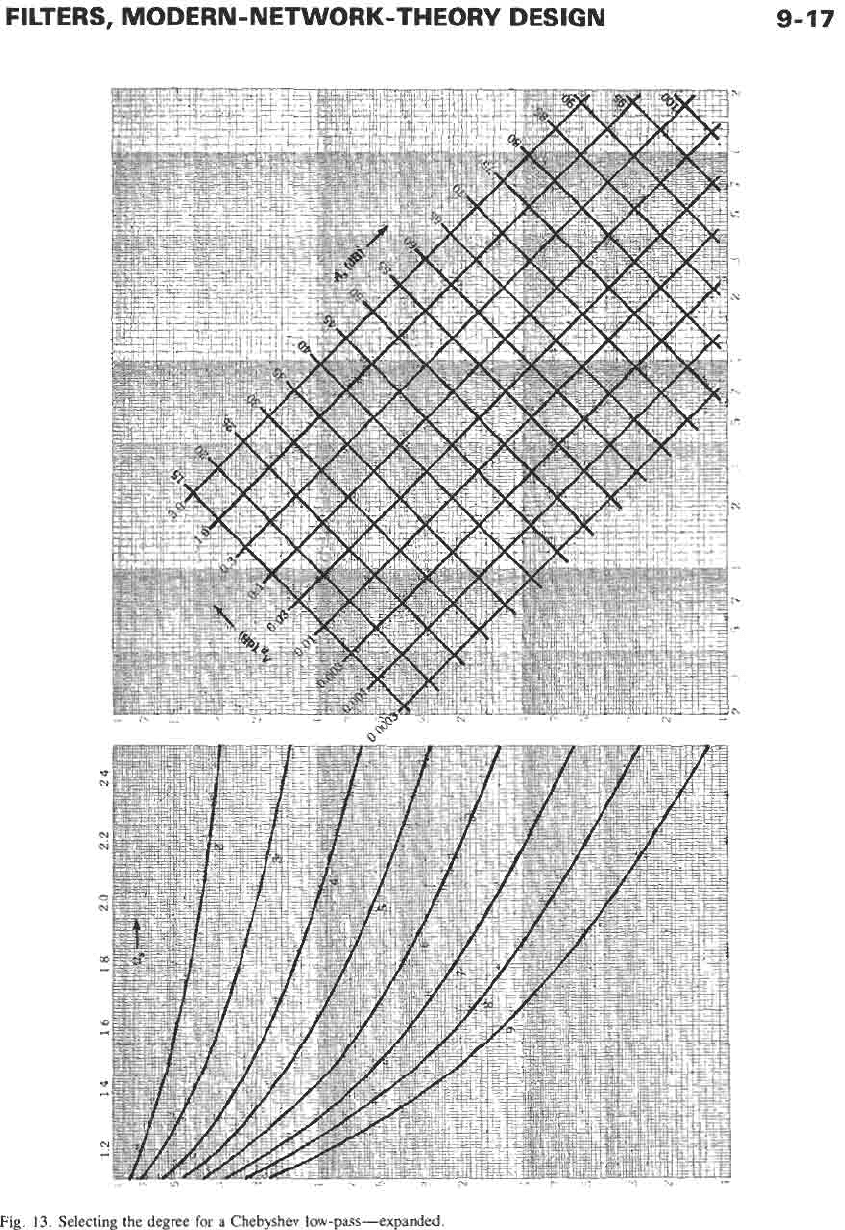
Fig.
13.
Selecting
the
degree
for
a
Chebyshev
low-pass-expanded.
9-18
REFERENCE
DATA
FOR ENGINEERS
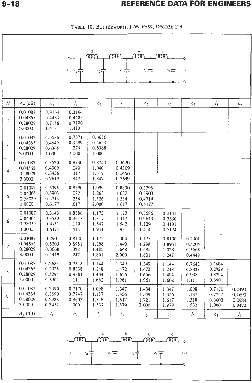
TABLE
10.
BUTTERWORTH
LOW-PASS, DEGREE
2-9
0.01087 0.3164
0.04365 0.4483
0.28029 0.7186
3.0000 1.413
0.01087 0.3686
0,04365 0.4649
0.28029 0.6368
3.0000 1.000
0.01087 0.3620
0,04365 0.4309
0.28029 0.5456
3.0000 0.7649
0.01087 0.3396
0.04365 0.3903
0.28029 0.4714
3.0000 0.6177
0.01087 0.3143
0.04365 0.3530
0.28029 0.4131
3.0000 0.5174
0.01087 0.2901
0,04365 0.3205
0.28029 0.3668
3.0000 0.4449
0.01087 0.2684
0.04365 0.2928
0.28029 0.3294
3.0000 0.3901
0.2490
0.2690
0.2988
0.3472
0.3164
0.4483
0.7186
1.413
0.7371 0.3686
0.9299 0.4649
1.274 0.6368
2.000 1.000
0.8740
0.8740 0.3620
1.040 1.040
0.4309
1.317
1.317 0.5456
1.847
1.847 0.7649
0.8890
1.099 0.8890
0.3396
1.022 1.263
1.022 0.3903
1.234 1.526
1.234 0.4714
1.617
2.000 1.617
0.6177
0.8586
1.173
1.173 0.8586
0.3143
0.9643 1.317
1.317
0.9643 0.3530
1.129 1.542
1.542
1.129 0.4131
1.414 1.931
1.931
1.414 0.5174
0.8130 1.175
1.304
1.175
0.8130
0.8981
1.298
1.440
1.298 0.8981
1.028
1.485 1.648
1.485 1.028
1.247 1.801
2.000
1.801 1.247
0.7642
1.144
1.349
1.349 1.144
0.8338
1.248
1.472
1.472 1.248
0.9381
1.404 1.656
1.656 1.404
1.111
1.662
1.961
1.961 1.662
0.7170
1.098
1.347
1.434 1.347
0.7747
1.187
1.456
1.549 1.456
0.8603
1.318 1.617
1.721 1.617
1.000
1.532
1.879
2.000 1.879
c2
13
c4
4
c6
0.2901
0.3205
0.3668
0.4449
0.7642 0.2684
0.8338 0.2928
0.9381 0.3294
1.111 0.3901
1.098
0.7170 0.2490
1.187
0.7747 0.2690
1.318
0.8603 0.2988
1.532
1.000 0.3472
11
CX
19
FILTERS, MODERN-NETWORK-THEORY DESIGN
9-19
The transformation
of
normalized circuit-element val-
ues
is
shown
in
Fig. 18.
LOW-PASS TO BAND-STOP
TRANSFORMATION
The transformation of a low-pass filter into a band-
stop filter
is
similar
to
the bandpass transform.
R
=
l/U(T
-
1/77)
The resulting transformation of circuit-element values is
shown in Fig. 19.
NUMERICAL EXAMPLES
Example
1
A
low-pass filter with input impedance of 600 ohms
and output impedance less than or equal to 600 ohms is
needed to pass frequencies up to 3.4 kHz with less than
0.05 dB attenuation and to attenuate frequencies at 8.0
kHz and above by at least 45 dB (Fig. 20). Design both
a Cauer-parameter and a Chebyshev low-pass to meet
the requirement.
The value of
a,
for the reference low-pass
is
calculated
R,
=
8000/3400
=
2.353
Cauer-Parameter Design-To determine the
Cauer-parameter low-pass, use Fig. 9 and proceed
as
follows.
Find the
45-dB
(A,)
line on the grid
(l),
and move to
the crossing with the
A,
=
0.05 line (2). From this
intersection (3), move to the left
to
intersect with the
curves of degree versus cutoff rate. Note that for degree
3,
R,
is
5.0;
for degree 4,
a,
G
2.9. Not until the
curve for degree
5
is reached is an
Rs
<
2.353 attained
(0,
G
1.65).
So
a fifth-order low-pass with
A,
=
45 dB,
A,
=
0.05 dB and
a,
=
1.65 can be designed to meet the
specified requirements. The tables included here are
limited, however,
so
they must be checked to see what is
available. From Table 4 (for filters of degree 5),
=
37"
with
10%
reflection (0.044 dB) and
a,
=
1.66164
meets the requirements. The normalized low-pass is
shown
in
Fig.
21.
Since only an
a,
5
2.353
is
required, some over-
design can be accomplished. Generally, the losses erode
the passband performance more rapidly than the stop-
band performance.
As
a result, the reference frequency
(fief)
can be chosen such thatti
=
8000
Hz.
fief
=
4.6245 kHz
and since
Rref
=
600 ohms,
Lief
=
20.6492
mH
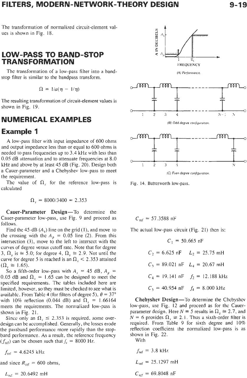
FREQUENCY
1Al
Performance.
1234
,\
-
1
,\
(E)
Odd-degree configurotion
T
-----
(Cj
Eoen-degree configuration.
Fig.
14.
Butterworth
low-pass.
Cref
=
57.3588 nF
The actual low-pass circuit (Fig.
21)
then is:
C,
=
50.665 nF
C2
=
6.625
nF
L,
=
25.75 mH
C,
=
89.021 nF
L4
=
20.67 mH
C4
=
19.141 nF
ft
=
12.188 kHz
C5
=
40.954 nF
f4
=
8.000
kHz
Chebyshev Design-To determine the Chebyshev
low-pass, use Fig. 12 and proceed as for the Cauer-
parameter design. Here
N
=
5
results in
0,
2.7, and
N
=
6
provides
a,
=
2.1. Thus
a
sixth-order filter
is
required. From Table
9
for sixth degree and
10%
reflection coefficient the normalized low-pass
is
as
shown in Fig. 22.
With
fief
=
3.8 kHz
Lief
=
25.1297 mH
CTef
=
69.8048 nF
9-20
REFERENCE
DATA
FOR ENGINEERS
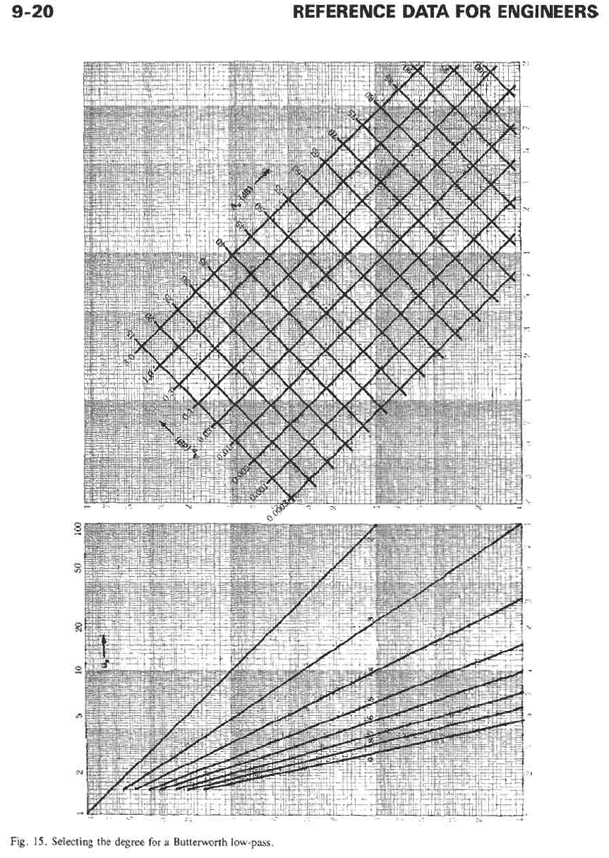
Fig.
15.
Selecting the degree for
a
Butterworth
low-pass.
FILTERS, MODERN-NETWORK-THEORY DESIGN
9-21
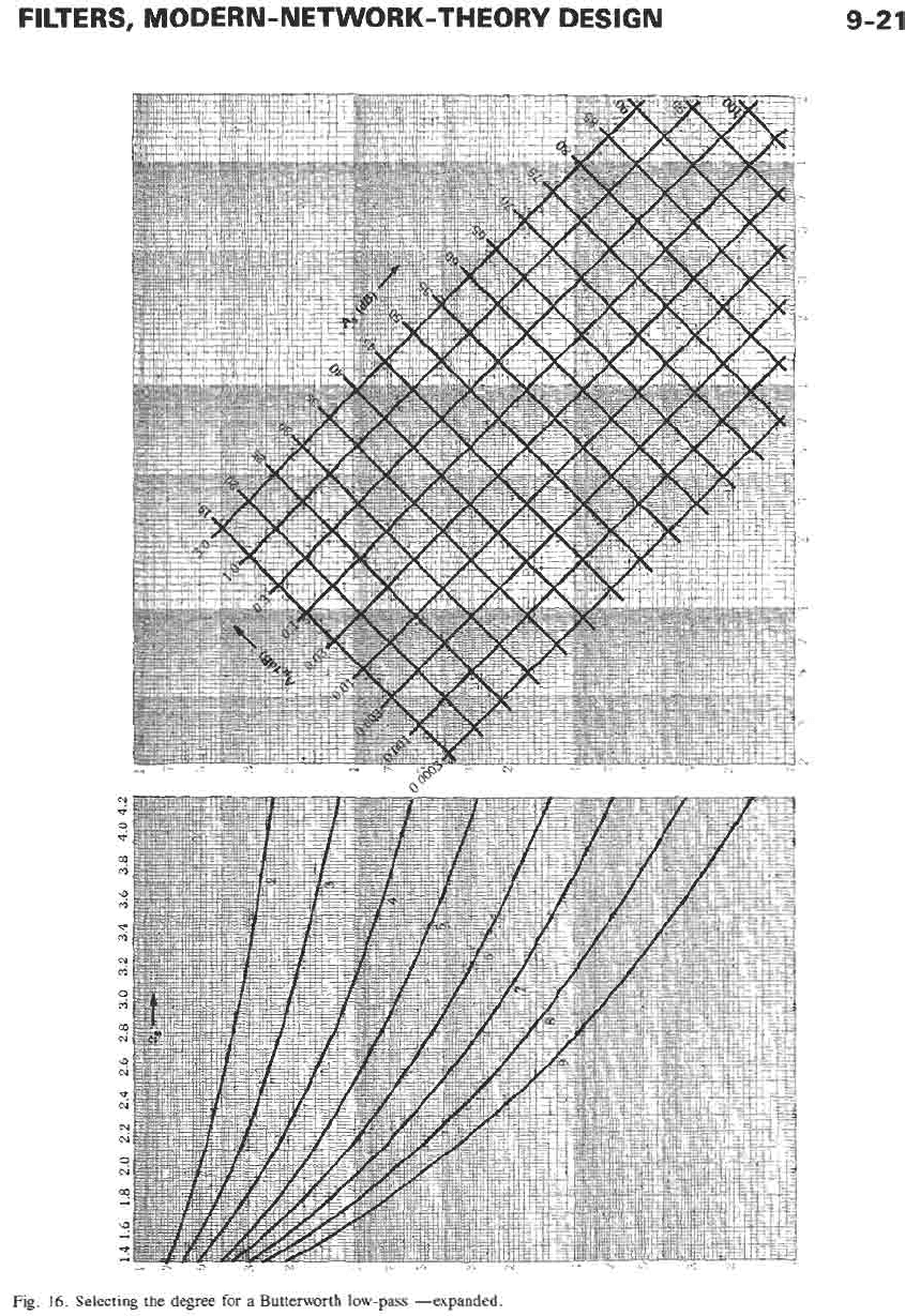
Fig.
16.
Selecting
the degree
for
a Butterworth low-pass -expanded
9-22
REFERENCE
DATA
FOR ENGINEERS
LOW-PASS
I
HIGH-PASS TRANSFORMATION
j
I=1'Co
/m
-if--
++
c=
1
'!,
i
LOW-PASS
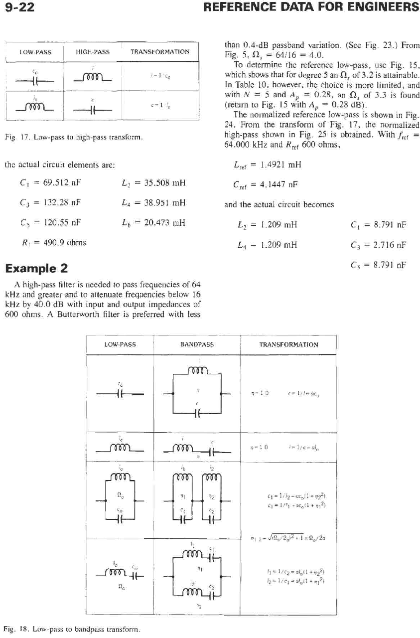
Fig.
17.
Low-pass
to
high-pass
transform
BANDPASS
the actual circuit elements are:
C,
=
69.512 nF
L,
=
35.508 mH
C3
=
132.28 nF
C5
=
120.55 nF
L,
=
38.951 mH
L,
=
20.473 mH
R,
=
490.9 ohms
Example
2
A
high-pass filter is needed to pass frequencies of 64
kHz and greater and to attenuate frequencies below 16
kHz by 40.0 dB with input and output impedances of
600 ohms.
A
Butterworth filter is preferred with less
than 0.4-dB passband variation. (See Fig. 23.)
From
Fig.
5,
fl,
=
64/16
=
4.0.
To
determine the reference low-pass. use Fig.
15,
which shows that for degree 5 an
fl,
of 3.2 is attainable.
In Table 10. however, the choice is more limited, and
with
N
=
5
and
A,
=
0.28, an
fls
of
3.3
is
found
(return to Fig. 15 with
A,
=
0.28 dB).
The normalized reference low-pass is shown in Fig.
24. From the transform of Fig. 17, the normalized
high-pass shown in Fig. 25 is obtained. With
fref
=
64.000 kHz and
R,,
600 ohms,
Lref
=
1.4921 mH
Cref
=
4.1447 nF
and the actual circuit becomes
I I
I
I
I
Fig.
18.
Low-pass
to
bandpass transform.
L2
=
1.209 mH
L,
=
1.209 mH
TRANSFORMATION
'i=
1
0
c=
l,l=ac
C,
=
8.791 nF
C,
=
2.716 nF
C5
=
8.791 nF
FILTERS, MODERN-NETWORK-THEORY DESIGN
10
cl=:
9-23
=3
z:
c.5
=:
rl
1
LOW-PASS
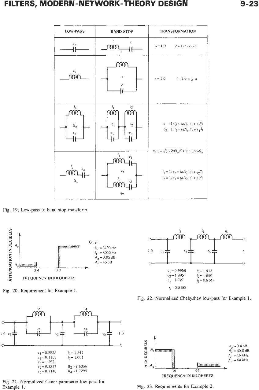
Fig. 19. Low-pass to band-stop transform.
BAND-STOP
'12
Given.
f,
=
3400
Hz
f,
=
8000
Hz
A,
=
0.05
dB
A,=45dB
5
FREQUENCY IN KILOHERTZ
Fig.
20.
Requirement for Example 1
TRANSFORMATION
'1=1.0
c=l/l=c,ja
Fig.
22.
Normalized Chebyshev low-pass for Example 1.
o!
1
q=08833
12=1.247
cz=O
1155
14=1
001
cj=1552
c4
=
0
3337
Rp
=
2.6356
cj=O
7140
R4=1
7299
Fig.
21.
Normalized Cauer-parameter low-pass
for
Example
1.
Ap=O
4dB
A,
=40
0
dB
is
=16kHr
ip
=64
kHz
i'li
Q4
ti&zaza
5
Q
A,
FREQUENCY IN KILOHERTZ
Fig,
23.
Requirements for Example
2.
REFERENCE
DATA
FOR ENGINEERS
C2
c4
c6
If
II
If
I\
=5
z:
1
c7
10
c,==
!l=04714
c2=1
234
Ij=
1526
c4=
1234
15=04714
Fig.
24.
Normalized
reference low-pass
for
Example
2.
--
--
1.0
10
~~~~~r;o
c1=
1/11
=
2
121
12=
1/c2=0
8104
c3=1/13=0
6553 14=l/cq=O8104
c5=1/Is=2 121
Fig.
25.
Normalized
high-pass
for Example
2.
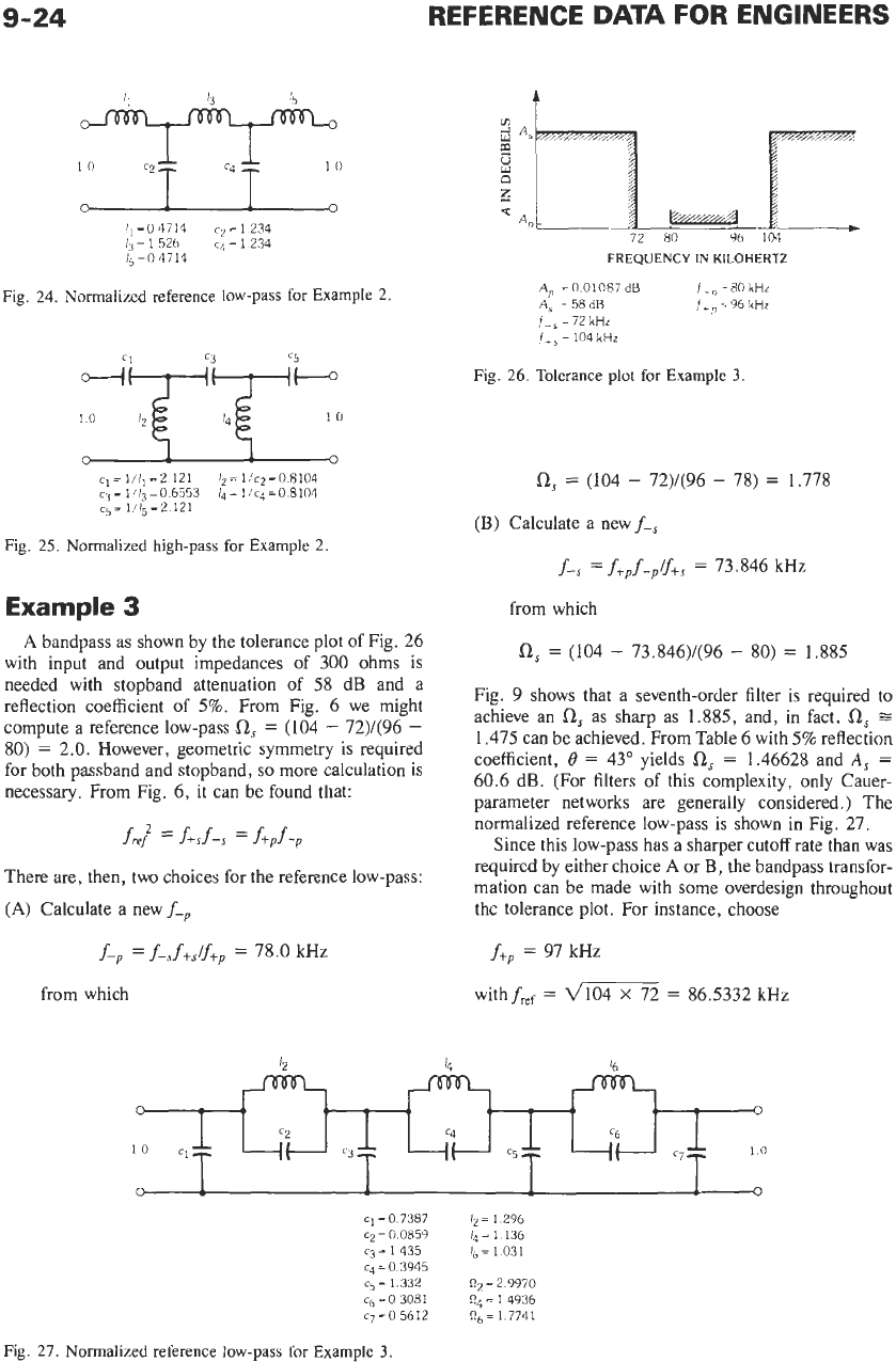
Example
3
A
bandpass as shown by the tolerance plot of Fig. 26
with input and output impedances of 300 ohms is
needed with stopband attenuation of 58 dB and a
reflection coefficient
of
5%.
From Fig. 6 we might
compute a reference low-pass
SZ,
=
(104
-
72)/(96
-
80)
=
2.0.
However, geometric symmetry is required
for both passband and stopband,
so
more calculation is
necessary. From Fig.
6,
it can be found that:
fie?
=
f+sf-s
=
ffpf-p
There are, then, two choices for the reference low-pass:
(A)
Calculate a new
f-,
f-,
=
f-,f+,/ftP
=
78.0 kHz
from which
c
FREQUENCY
IN
KILOHERTZ
A,
=O
01087
dB
iL,=SO
kHr
A,
=58dB
f+,,=96
kHz
f-$
=
72
kHr
i,,
=
104
kHz
Fig.
26.
Tolerance
plot
for
Example
3.
SZ,
=
(104
-
72)/(96
-
78)
=
1.778
(B)
Calculate a new
f-,
f-,
=
ftpf-p/j+s
=
73.846 kHz
from which
SZ,
=
(104
-
73.846)/(96
-
80)
=
1.885
Fig. 9 shows that a seventh-order filter
is
required to
achieve an
0,
as sharp as 1.885, and, in fact,
Os
=
1.475 can be achieved. From Table 6 with
5%
reflection
coefficient,
0
=
43" yields
SZ,
=
1.46628 and
A,
=
60.6 dB. (For filters of this complexity, only Cauer-
parameter networks are generally considered.) The
normalized reference low-pass is shown in Fig. 27.
Since this low-pass has a sharper cutoff rate than was
required by either choice
A
or
B,
the bandpass transfor-
mation can be made with some overdesign throughout
the tolerance plot. For instance, choose
f+,
=
97 kHz
with
fief
=
=
86.5332 kHz
Fig.
27.
Normalized
reference
low-pass
for
Example
3.
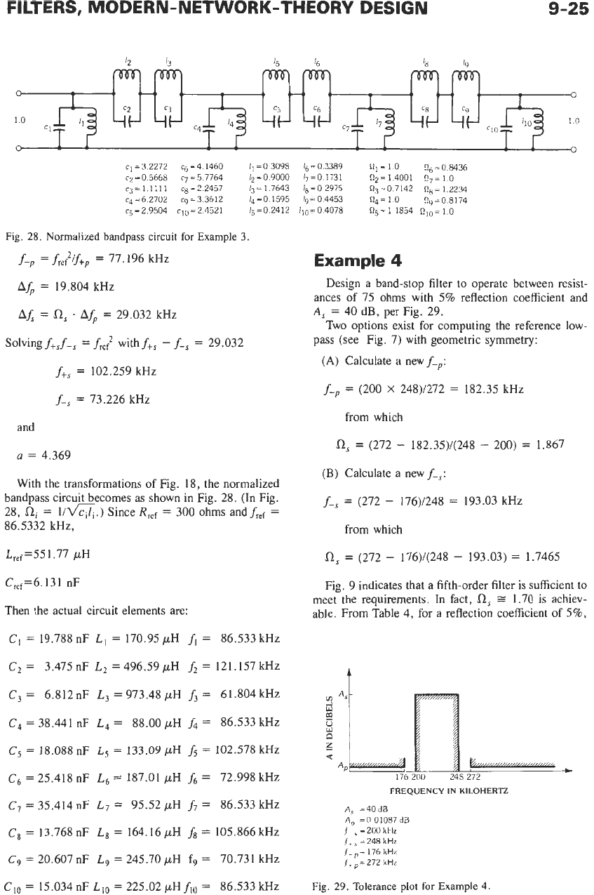
FILTERS, MODERN-NETWORK-THEORY DESIGN
9-25
12
13
'5
18
19
0
I
CI)
(.
-1
4,
48
4-1
<I
c2
=3
c5
C6
c8 c9
10
cl==
'1
i(-
-I(-
ik
+I-
-I(-
ik
0
1
1
1
&
0
c1=32272
cg=4 1460 I,=O3098 16=0.3389
nl=l
0
n6=08436
c2=0.5668 c7=57764
12=09000 17=0.1731
Q2=14001
n7=10
c3=l.llll
cg=22457 13=17643
lg=02975
R3=07142 n8=1.2234
c4=6.2702
cq=33612
14=0 1595
19~04453
Qq=l
0
Qg=08174
c5=2.9504 c10=2.4521
15=02412 110=04078
ng=1
1854
RIO=1
0
Fig.
28.
Normalized bandpass
circuit
for
Example
3.
f-,
=
f,,;if+,
=
77.196 kHz
A&
=
19.804 kHz
AX
=
0,
.
A&
=
29.032 kHz
Solving
f+,f-,
=
f,f"
with
ft,
-
f-,
=
29.032
ft,
=
102.259 kHz
f-,
=
73.226 kHz
and
a
=
4.369
With the transformations of Fig. 18, the normalized
bandpass circuit becomes as shown in Fig. 28. (In Fig.
28,
SZi
=
Urn.)
Since
Rref
=
300 ohms andfref
=
86.5332 kHz,
L,,f=551 .77 pH
Cref=6.131 nF
Then the actual circuit elements are:
CI
=
19.788 nF
L,
=
170.95 pH
fi
=
86.533 kHz
C2
=
3.475
nF
L,
=
496.59 pH
fi
=
121.157 kHz
C3
=
6.812 nF
L3
=
973.48 pH
f3
=
61.804 kHz
C4
=
38.441
nF
L4
=
88.00
pH
f4
=
86.533 kHz
C,
=
18.088 nF
L,
=
133.09
pH
fs
=
102.578 kHz
c6
=
25.418 nF
L6
=
187.01 /AH
f6
=
72.998 kHz
C7
=
35.414 nF
L7
=
95.52 pH
f7
=
86.533 kHz
Cx
=
13.768 nF
L,
=
164.16 pH
fx
=
105.866 kHz
C9
=
20.607 nF
L9
=
245.70 pH fg
=
70.731 kHz
Clo
=
15.034 nF
L,,
=
225.02 pHfiO
=
86.533 kHz
Example
4
Design a band-stop filter to operate between resist-
ances of 75 ohms with
5%
reflection coefficient and
A,
=
40 dB, per Fig. 29.
Two options exist for computing the reference low-
pass (see Fig. 7) with geometric symmetry:
(A)
Calculate a new
f-,:
f-,
=
(200
X
248)/272
=
182.35 kHz
from which
SZ,
=
(272
-
182.35)/(248
-
200)
=
1.867
(B) Calculate a new
f-s:
f-,
=
(272
-
176)/248
=
193.03 kHz
from which
a,
=
(272
-
176)/(248
-
193.03)
=
1.7465
Fig. 9 indicates that a fifth-order filter is sufficient to
meet the requirements. In fact,
a,
=
1.70 is achiev-
able, From Table 4, for a reflection coefficient of
5%,
t
176
200
248 272
FREQUENCY
IN
KILOHERTZ
A,
=40dB
A?
=O
01087
dB
(-,=200kHz
f,,
=
248
kHz
(-,,=
176
kHz
f+,=272
kHr
Fig.
29.
Tolerance
plot
for
Example
4.