Middleton W.M. (ed.) Reference Data for Engineers: Radio, Electronics, Computer and Communications
Подождите немного. Документ загружается.

9-26
REFERENCE
DATA
FOR ENGINEERS
c-0
c2
8
=
36” produces
a,
=
1.7013 and
A,
=
40.8 dB. The
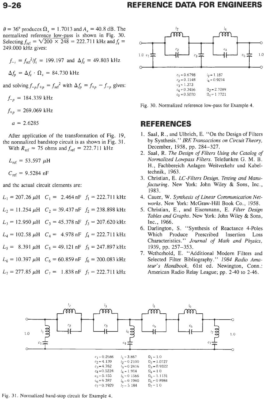
normalized reference low- ass is shown in Fig. 30.
Selecting
fief
=
200
X
248
=
222.71
1
kHz andf,
=
249.000 kHz gives:
f-,
=
f,;?/f,
=
199.197 and
AA
=
49.803 kHz
A&
=
Ah
.
R,
=
84.730 kHz
and solving
f-,f+,
=
f,,;?
with
A&
=
f+,
-
f-,
gives:
f-,
=
184.339 kHz
f+,
=
269.069 kHz
a
=
2.6285
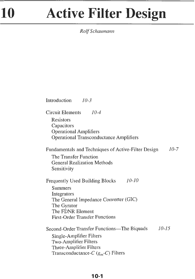
After application of the transformation
of
Fig. 19,
the normalized bandstop circuit is as shown in Fig. 3 1.
With
Rref
=
75 ohms and
fief
=
222.711 kHz
L,f
=
53.597 pH
Cref
=
9.5284 nF
and the actual circuit elements are:
L,
=
207.26
pH
C,
=
2.464 nF
fi
=
222.711 kHz
L2
=
11.254 pH
C2
=
39.437 nF
f2
=
238.898 kHz
L,
=
12.950 pH
C3
=
45.378 nF
f3
=
207.620 kHz
L4
=
102.58 pH
C4
=
4.978nF
f4
=
222.711 kHz
L5
=
8.391 pH
C5
=
49.121 nF
f5
=
247.897 kHz
L6
=
10.397
pH
c6
=
60.859 nF
fs
=
200.083
ldlZ
L7
=
277.85
pH
C7
=
1.838 nF
f7
=
222.711 kHz
c_(J
0
c3
c5
c6
I1
11
It
cl=06798
12=1
187
c2=0
1148
14=09214
c4=0 3456
R2=2
7089
cg=O 5070
Rq=
17721
c3
=
1
373
Fig.
30.
Normalized reference low-pass for Example
4.
REFERENCES
1. Saal,
R.,
and Ulbrich, E. “On the Design
of
Filters
by Synthesis.
’
’
IRE Transactions on Circuit Theory,
December, 1958, pp. 284-327.
2. Saal,
R.
The Design
of
Filters Using the Catalog
of
Normalized Lowpass Filters.
Telefunken G. M.
€3.
H., Fachbereich Anlagen Weitverkehr und Kabel-
technik, 1963.
3. Christian, E.
LC-Filters Design, Testing and Manu-
facturing.
New York: John Wiley
&
Sons, Inc.,
1983.
4. Cauer, W.
Synthesis
of
Linear Communication Net-
works.
New York: McGraw-Hill Book Co., 1958.
5.
Christian,
E.,
and Eisenmann, E.
Filter Design
Tables and Graphs.
New York: John Wiley
&
Sons,
Inc., 1966.
6. Darlington,
S.
“Synthesis
of
Reactance 4-Poles
Which Produce Prescribed Insertion Loss
Characteristics.
”
Journal
of
Math and Physics,
7. Wetherhold, E. “Additional
Modern
Filters and
Selected Filter Bibliography.
”
1984
Radio
Ama-
teur’s Handbook,
61st ed. Newington, Conn.:
American Radio Relay League; pp. 2-40 to 2-46.
1939, pp, 257-353.
cl
=
0
2586
c2=4
139
c3
=
4 762
cq
=O
5224
cj=5
155
cb
=
6
387
cj=O
1929
11=3867
n,=lO
12=0
2100
n2=
10727
13
=
0
2416
n3
=
0
9322
&,=I914
nq=lO
ls=O
1566
Rj=1
1131
16
=
0
1940
Rg
=
0
8984
1j=5
184
Rj=1
0
Fig.
3
1.
Normalized band-stop circuit for Example
4
10
Active Filter
Design
Rolf
Schaumann
Introduction
10-3
Circuit Elements
10-4
Resistors
Capacitors
Operational Amplifiers
Operational Transconductance Amplifiers
Fundamentals and Techniques
of
Active-Filter Design
10-7
The Transfer Function
General Realization Methods
Sensitivity
Frequently Used Building Blocks
10-10
Summers
Integrators
The General Impedance Converter (GIC)
The Gyrator
The FDNR Element
First-Order Transfer Functions
Second-Order Transfer Functions-The Biquads
10-15
Single-Amplifier Filters
Two- Amplifier Filters
Three-Amplifier Filters
Transconductance-C
(g,-C)
Filters
10-1
10-2
REFERENCE
DATA
FOR ENGINEERS
High-Order Transfer Functions
10-23
Cascade Realization
Multiple-Feedback Topologies
Ladder Simulation
Switched-Capacitor Filters
10-34
Sampled-Data Filter Systems
The Operation
of
Ideal SC Filters
SC Integrators
SC z-Domain Biquadratic Transfer Functions
Parasitic-Insensitive SC Biquads
Low-Pass Notch Example
Other Topologies and Comments
The information in this chapter enables the engineer
to design a wide variety of practical active filters for
operation in the audio-frequency range, and higher if
fast operational amplifiers (op amps) are available. If
operational transconductance amplifiers (OTAs) are
used, filters even into the range of hundreds of mega-
hertz can be designed. The equations presented permit
the user to complete the design and arrive
at
a fairly
comprehensive evaluation of the performance to be
expected from the filter, without requiring complicated
mathematics. Out of the countless different filters pro-
posed in the technical literature, only those few cir-
cuits that have been proven to be practical, state-of-
the-art designs are discussed in this chapter. Given the
limited space available in a reference volume such
as
this, sufficient information can be provided only for
the design of filters of relatively simple specifications.
If system requirements are very stringent, the reader
should consult the many excellent books" or papers
referred to in the text.
digital-circuit integration, enabling digital and analog
circuitry to coexist on the same
LSI
chip.
For applications at much higher frequencies, such
as
in the read/write channels of magnetic disk recording
systems or high-frequency communication systems,
active
RC
filters based on operational amplifiers prove
insufficient because of the op amps' bandwidth limita-
tions.
In
these cases, when signals in the tens
to
hun-
dreds of megahertz, or even gigahertz, must be
processed, the designer uses operational transconduc-
tance amplifiers (OTAs)
as
active devices. OTAs are
voltage-to-current converters described by their
transconductance parameter
g,.
It is quite possible to
design OTAs with much higher bandwidth than op
amps (up to several hundred megahertz and even giga-
hertz)
so
that analog active filters in the radio-fre-
quency
(RF)
range become possible. Because discrete
OTAs are not readily available, this latter technology is
used mainly for integrated filters, where the use of
only OTAs and capacitors enables the designer to
implement high-frequency analog
g,-C
filters compat-
ible with digital CMOS technology. The filter perfor-
mance depends unavoidably on OTA parameters,
which must somehow be tuned. Techniques for
ban-
dline these problems are becoming available on
ICs.$
INTRODUCTION
The technology of hybrid and monolithic integrated
circuits has profoundly influenced the design and
implementation of filters in the audio-frequency range
and beyond. Frequency limitations are always set by
the bandwidth of the available op amps. Integration
has allowed the realization of filters that
are
small in
size, inexpensive, and mass-producible. During the
past
25
years, active
RC
networks, typically compris-
ing resistors, capacitors, and operational amplifiers,
have been the primary means of hybrid-integrated
audio-filter implementation. Active
RC
filters have
eliminated the need for the bulky, expensive inductors
required in passive implementations, and tuning is
simplified and usually involves the adjustment of only
resistors. Furthermore, tuning can be automated in
manufacture, using commercial laser trimming sys-
tems. In addition, active
RC
filters have provided
opportunities for standardization and modularity that
significantly simplify design and fabrication.
Switched-capacitor (SC) networks? have allowed
audio-frequency active filters to be realized with the
metal-oxide-semiconductor
(MOS)
large-scale-inte-
gration
(LSI)
technologies associated with digital net-
works. Switched-capacitor filters typically contain
capacitors, MOSFET switches, and operational ampli-
fiers. The switches are operated
by
clock signals that
are digitally derived from
a
stable frequency source
such as a crystal-controlled oscillator. The characteris-
tics of the filter are then determined by capacitor ratios
and the clock frequency, both inherently precise and
stable parameters. Hence, SC filters rarely require
trimming. The most important attribute of SC filters is
that their implementation in silicon is compatible with
At gigahertz frequencies, also passive
LC
filters can
be implemented in integrated form because inductors
of very small values (typically, nH) can be realized on
an IC
as
single-layer or multiple-layer metal spirals.
These inductors are very lossy, with quality factors of
the order of only
10,
so
that active
loss
compensation
techniques are usually employed;
also,
the spirals con-
sume a relatively large silicon area, but the filters can
be shown to have a lower noise and superior dynamic
range than those using
g,-C
techniques. For an over-
view of this design approach, the reader may consult
Reference
28.
Integrated
analog filters, especially for high-fre-
quency applications, must be designed in fully differ-
ential, balanced form. Normally these filters will share
an IC chip with digital circuitry where ground and
power-supply lines (ac ground) are noisy, due, for
example, to digital switching transients. Referring a
signal to ac ground will, therefore, likely result in
a
severely restricted dynamic range (low signal-to-noise
ratio). This problem is greatly reduced by referring
two differential signal lines with equal and opposite
signal voltages
+vJ2
to each other:
vo
=
vS/2-(-v,/2)
=
v,.
Noise voltages on power-supply and ground lines
appear as common-mode signals and
are
rejected in
the differential circuit. Because OTA-based filters are
intended mainly for IC implementation and for high
frequencies, the corresponding examples below will be
shown in differential form. Conversions from single-
ended to differential form are straightforward.§
*
References
1-10,
t
Reference
10.
#
References
6,7,
and
11-14.
§
Reference
6.
Although the design of high-frequency integrated
OTA-C filters is, in principle, quite simple, in practice
numerous constraints must be considered and these are
beyond
this
introductory discussion. The presentation in
this book should make the reader aware of the possibili-
ties, but details are left
to
References
6,7,
and
10-14.
Active filters are used extensively in instsumentation
and communication systems.
To
design these circuits,
whether
in
active
RC
(based
on
op amps or OTAs),
g,-C,
or
SC
techniques, one must first understand what an
active filter is and how its performance requirements are
specified.
An
electric filter is a network that transforms
an input signal in some specified way into a desired out-
put signal. Although many applications exist where fil-
ter requirements are set in terms of time-domain
specifications, the majority of filters are designed to sat-
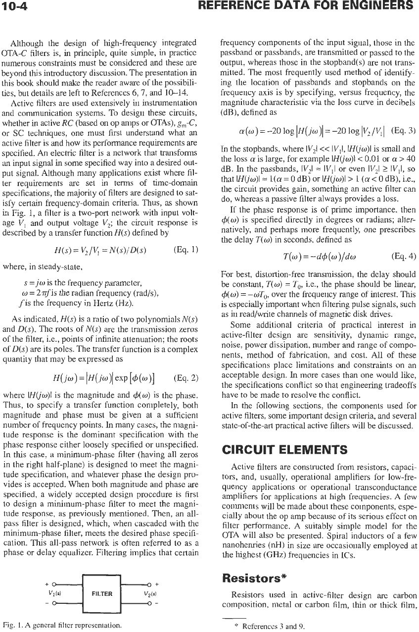
isfy certain frequency-domain criteria. Thus, as shown
in
Fig.
1,
a filter is a two-port network with input volt-
age
VI
and
output
voltage
V2;
the circuit response
is
described by a transfer functionH(s) defined by
H(s)
=
V2/V,
=
N(s)/D(s)
0%.
1)
where, in steady-state,
s
=jw
is the frequency parameter,
w
=
2$is the radian frequency (rad/s),
fis the frequency in Hertz (Hz).
As indicated,
H(s)
is a ratio of two polynomials
N(s)
and
D(s).
The roots of
N(s)
are the transmission zeros
of the filter, i.e., points of infinite attenuation; the roots
of
D(s)
are its poles. The transfer function is a complex
quantity that may be expressed as
where
IHuw)l
is the magnitude and
4(w)
is the phase.
Thus, to specify a transfer function completely, both
magnitude and phase must be given at a sufficient
number of frequency points.
In
many cases, the magni-
tude response is the dominant specification with the
phase response either loosely specified or unspecified.
In
this case, a minimum-phase filter (having all zeros
in the right half-plane) is designed to meet the magni-
tude specification, and whatever phase the design pro-
vides
is
accepted. When both magnitude and phase are
specified, a widely accepted design procedure is
first
to design a minimum-phase filter
to
meet the magni-
tude response, as previously mentioned. Then,
an
all-
pass filter is designed, which, when cascaded with the
minimum-phase filter, meets the desired phase specifi-
cation.
This
all-pass network is often referred
to
as a
phase or delay equalizer. Filtering implies that certain
frequency components of the input signal, those in the
passband or passbands, are transmitted or passed to the
output, whereas those in the stopband(s) are not trans-
mitted. The most frequently used method of identify-
ing the location of passbands and stopbands
on
the
frequency axis is by specifying, versus frequency, the
magnitude characteristic via the
loss
curve in decibels
(dB), defined as
In
the
stopbands, where
IV21
<<
lVll,
IH(jw)l
is small and
the loss
a
is large, for example
H(jw)l<
0.01
or
a
>
40
dB.
In
the passbands,
IV21
=
IV,I
or even
IV21
2
WII,
so
that
IHuw)l=
l(a
=
0
dB) or
IH(jw)l>
1
(a
<
0
dB), Le.,
the circuit provides gain, something an active filter can
do, whereas a passive filter always provides a loss.
If the phase response is of prime importance. then
4(w)
is specified directly in degrees or radians; alter-
natively, and perhaps more frequently, one prescribes
the delay
T(w)
in seconds, defined as
T(w)
=
-d4(w)/dw
(Eq.
4)
For best, distortion-free transmission, the delay should
be constant,
T(w)
=
To,
i.e., the phase should be linear,
4(w)
=
-wTo,
over the frequency range of interest.
This
is especially important when filtering pulse signals, such
as in read/write channels of magnetic disk drives.
Some additional criteria of practical interest
in
active-filter design are sensitivity, dynamic range,
noise, power dissipation, number and range
of
compo-
nents, method of fabrication, and cost. All of these
specifications place limitations and constraints
on
an
acceptable design.
In
more cases than one would like,
the specifications conflict
so
that engineering tradeoffs
have to be made to resolve the conflict.
In
the following sections, the components used for
active filters, some important design criteria, and several
state-of-the-art practical active filters will be discussed.
CIRCUIT
ELEMENTS
Active filters
are
constructed from resistors, capaci-
tors, and, usually, operational amplifiers for low-fre-
quency applications or operational transconductance
amplifiers for applications at high frequencies.
A
few
comments will be made about these components, espe-
cially about the op amp because of its serious effect
on
filter performance. A suitably simple model for the
OTA will also be presented. Spiral inductors of a few
nanohenries (nH) in size are occasionally employed at
the highest
(GHz)
frequencies
in
ICs.
Resistors*
Resistors used in active-filter design are carbon
composition, metal or carbon film, thin or thick film,
Fig.
1.
A
general
filter representation.
*
References
3
and
9.
ACTIVE FILTER
DESIGN
10-5
wirewound, and diffused. The selection depends on
cost,
on
the technology used to implement the filter,
and
on
filter requirements. Carbon composition resis-
tors are the least expensive, but they have large toler-
ances and temperature coefficients. Further, tracking is
not
very good
so
that composition resistors should be
used only for noncritical applications. Metal-film and
wirewound resistors, although more expensive, are
better than composition types in all respects and are
the most frequently used resistors in active-filter
design today. Wirewound resistors have somewhat
larger parasitics
(L
and
C)
than metal-film resistors
and should
not
be used for high-frequency applica-
tions.
Capacitors*
Of the numerous different types of capacitors avail-
able, those commonly used in active filters are ceramic
disc, Mylar, polystyrene, Teflon, and thin-film capaci-
tors. Again, the selection depends
on
factors such as
cost, available range, tolerances, temperature coeffi-
cients, and dissipation factor (loss). Ceramic and Mylar
capacitors are the least expensive types and have the
highest loss; they should be used only for noncritical
applications. Teflon, thin-film, and especially polysty-
rene (or for small values, mica) capacitors are more
expensive but have much lower dissipation factors and
are therefore better suited for critical filter designs. Of
course, in integrated implementations, on-chip metal-
oxide-semiconductor
(MOS)
capacitors are being used.
In setting filter parameters, apart from tolerances
and temperature coefficient, the dissipation factor
(DF)
or quality factor
(e,)
is of some importance. If loss is
modeled by means
of
a resistor
R,
in parallel with the
capacitor
C,
Q,
and
DF
are defined as
Q,
=
l/DF
=
wCR,
(Eq.
5)
where
w
is some critical frequency of interest, usually
chosen at the passband edge. It should also be remem-
bered that
Q,
is a strong function of temperature. Typi-
cal values of
Q,
range from less than 100 (ceramic) up
to several thousand (polystyrene).
Operational Amplifiers
Although, as was mentioned, IC filters preferably
use OTAs, the active element used
in
the vast majority
of
all discrete active
RC
filters and integrated SC filters
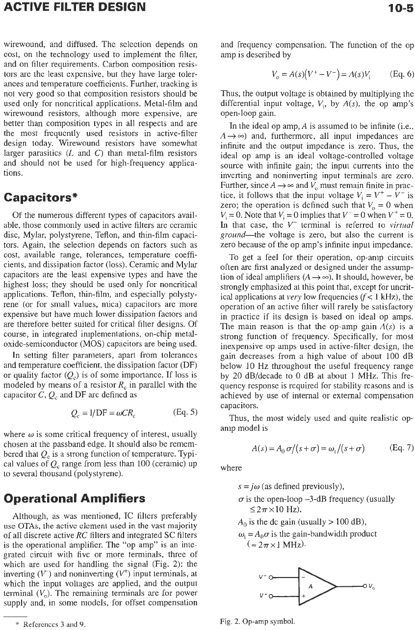
is the operational amplifier. The “op amp” is an inte-
grated circuit with five or more terminals, three of
which are used for handling the signal (Fig.
2):
the
inverting
(V)
and noninverting
(v‘)
input terminals, at
which the input voltages are applied, and the
output
terminal
(VJ.
The remaining terminals
are
for power
supply and, in some models, for offset compensation
*
References
3
and
9.
and frequency compensation. The function of the op
amp is described by
V,
=
A(s)(V+
-
V-)
=
A(s)Y
(Eq.
6)
Thus, the output voltage is obtained by multiplying the
differential input voltage,
V,,
by
A(s),
the op amp’s
open-loop gain.
In
the ideal op amp,
A
is assumed
to
be infinite (i.e.,
A+-)
and, furthermore, all input impedances are
infinite and the output impedance is zero. Thus, the
ideal op amp is
an
ideal voltage-controlled voltage
source with infinite gain; the input currents into the
inverting and noninverting input terminals are zero.
Further, since
A
-+
and
V,
must remain finite in prac-
tice, it follows that the input voltage
Vi
=
V+
-
V-
is
zero; the operation is defined such that
V,
=
0
when
Vi
=
0.
Note that
V,
=
0
implies that
V-
=
0
when
V+
=
0.
In
that case, the
V-
terminal is referred to
virtual
ground-the voltage is zero, but also the current is
zero because of the op amp’s infinite input impedance.
To get a feel for their operation, op-amp circuits
often are first analyzed or designed under the assump-
tion of ideal amplifiers
(A
+
m).
It should, however, be
strongly emphasized at
this
point that, except for uncrit-
ical applications at
very
low frequencies
(f<
1
kHz), the
operation of an active filter will rarely be satisfactory
in practice if its design is based
on
ideal op amps.
The main reason is that the op-amp gain
A(s)
is a
strong function of frequency. Specifically, for most
inexpensive op amps used in active-filter design, the
gain decreases from a high value of about 100 dB
below
10
Hz throughout the useful frequency range
by
20
dB/decade to
0
dB at about
1
MHz. This fre-
quency response is required for stability reasons and is
achieved by use of internal or external compensation
capacitors.
Thus, the most widely used and quite realistic op-
amp model is
A(s)=A,a/(s+a)=wt/(s+a)
(Eq.
7)
where
s
=
jw
(as defined previously),
ais the open-loop
-343
frequency (usually
A,
is the dc gain (usually
>
100 dB),
o,
=
A,a
is the gain-bandwidth product
<
2.rr
x
10
Hz),
(=2.rrxl
MHZ).
Fig.
2.0~-amp
symbol.
10-6
REFERENCE
DATA
FOR ENGINEERS
In
most practical applications,
Is1
>>
u,
so
that, instead
of
Eq.
7,
a commonly used model is
A(s)
=
w,/s
(Eq.
8)
Analyzing an active filter with op amps represented by
Eqs.
7
or
8
rather than by a simple constant-gain
model increases the degree of the describing network
function (Eq.
1)
by one for each amplifier used. Thus,
the filter acquires parasitic poles and zeros in addition
to suffering shifts of the nominal pole-zero locations.
Stated differently,
the
two polynomials
N(s)
and
D(s)
in Eq.
1
change from their prescribed ideal form. It is
for this reason that filters designed with the assump-
tion of ideal amplifiers
(w,
-+
w)
do not normally have
a satisfactory frequency response but show a poten-
tially large deviation from their nominal performance
because of finite
wt.
Occasionally, a filter will behave unpredictably,
possibly even oscillate, in spite of a design based
on
the op-amp model of Eqs.
7
or
8.
The reason may
often be found in
the
fact that, whereas the representa-
tion of
Eq.
7
describes the op-amp
gain
very well, the
phase shift is larger than indicated by
Eq.
7.
An ade-
quate remedy is to multiply Eq.
7
by an “excess phase
factor,” exp(-j
w/w2),
where
w2
is a normalizing fre-
quency of value
w2
=
3w,,
and to use this augmented
model in the analysis. Because for all practical pur-
poses
w2
is much larger than the operating frequency
w,
we can set exp(-s/w2)
=
1
-
s/w2
to
keep the alge-
bra manageable; i.e.,
a
very accurate op-amp model
for use in highly selective filters at fairly high frequen-
cies is
In
most applications, however, the use of
Eq. 8
leads to
entirely satisfactory results.
Further op-amp characteristics of concern
to
filter
designers are slew rate and dc offset voltage. Slew rate
(SR),
given in volts per microsecond, refers to the
maximum rate of change of a signal voltage that the
amplifier can maintain at its output. Violating slew-rate
limitations results
in
gross signal and/or transfer-func-
tion distortion and should be avoided. Thus, if
v,
(t)
=
Vo
sin
wt
is the amplifier output voltage, one
needs to observe
V,
<
SR/w
.
For example, if
SR
=
0.7
V/p
(a typical value for inexpensive op
amps)
and the
signal frequency is
15
kHz, the signal amplitude must
satisfy
Vo
5
7.3
V to avoid slew-rate limitations.
There are two main reasons* for offset voltage. One
is
the need for dc input bias currents into the input
stage of bipolar op amps. (There is
no
input bias cur-
rent
in
MOS
op amps.) The second arises from imbal-
ances in the input stage. To be able to provide the input
bias, dc paths must exist from the inverting and nonin-
verting input terminals to ground.
To
minimize offset,
the resistances seen from these two terminals back into
the network ought to be equal. Then the voltage drops
caused by the two bias currents at the op-amp inputs
are equal and the direct differential input voltage
is
zero, resulting in zero contribution to offset.
In
prac-
tice, things
are
not quite
so
simple because imbalances
in
the op-amp input stage cause the bias currents
not
to
be exactly equal, resulting in a finite differential direct
input voltage. This voltage
is
multiplied by the dc
closed-loop gain (see below), leading to an output off-
set voltage that, however, h-equently can be reduced
to
zero by means
of
a potentiometer connected
to
the off-
set-adjust temiinals of the op
amp.
All amplifier parameters, especially the important
terms
A,,
and
ut,
are strong functions of bias voltages
and temperature, and in general are not well deter-
mined or even predictable from unit to unit. Therefore,
one strives to minimize filter dependence
on
these
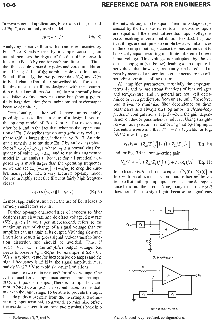
parameters and always uses op amps in
closed-loop
feedback
configurations (Fig.
3)
where the gain depen-
dence
on
device parameters is reduced. Using straight-
forward analysis, and remembering that op-amp input
currents are zero and that
V-
=
-V2/A,
yields for Fig.
3A
the inverting gain
and for Fig.
3B
the noninverting gain
In
both circuits,
R
is chosen to equal
l/[Y,(O)
+
Y2(0)]
in
line with the above discussion about offset minimiza-
tion so that both op-amp inputs see the same dc imped-
ance back into the circuit. Note, though, that resistor
R
does not affect the signal gain because
no
signal cur-
/uI
(A)
lnuertlng
galn
-
(E)
Nonlnuertlng
galn
Fig.
3.
Closed-loop feedback configurations.
*
References
3,
7,
and
9
ACTIVE FILTER DESIGN
10-7
rent flows through it. Thus, for simplicity, in the
remaining discussion in this chapter,
R
will be
neglected; Le.,
R
=
0
is assumed.
For ideal amplifiers, or, in practice, in the frequency
range where
IA(
jo)l>>
11
+
Z2( jw)/Z, (jo)]
,
Eqs. 10
and
11
reduce to
and
respectively. As desired, the closed-loop gain functions
are
then independent of amplifier parameters and are
determined only by presumably accurately adjustable
and stable external impedances. The quantities
Z,(s)
and
Z2(s)
are
finally chosen to yield the desired fre-
quency dependence of the gain. For example, setting
Z,
=
R,
and
Z,
=
KR,
results, of course, in the well-
known
amplifiers of inverting gain
-K
(Fig. 3A) and
noninverting gain
1
+
K
(Fig.
3B).
More will be said
later about these important building blocks.
are
parasitic input and output capacitors of some small
fraction of a picofarad (pF) in size. These capacitors
must
be accounted for in accurate designs at very high
frequencies. The OTA's bandwidth
is
several hundred
megahertz or, depending on technology and design,
reaches the gigahertz range. From these few numbers it
can be seen that, in contrast to op amps, OTAs can be
treated as almost ideal components for most active-fil-
ter design tasks. Only at the highest frequencies must
OTA nonidealities, in particular the parasitic capacitors
and the parasitic pole
IT,
be taken into account. Fig.
4B
shows an OTA with differential output terminals, and
Fig.
4C
shows an OTA with multiple differential inputs
(here two) and differential outputs realizing
IT=I;=gnl[(v,'-V,-)+(V2+-V;)]
(Eq. 16)
FUNDAMENTALS AND
FILTER DESIGN
TECHNIQUES OF ACTIVE-
The Transf er Function
In Eq.
1
the transfer characteristic of a filter was
Operational Transconductance
Amplifiers
introduced as a ratio of polynomials, i.e.,
As
mentioned previously, an operational transcon-
ductance amplifier (OTA)
is
a voltage-to-current con-
verter described by the conversion parameter
g,,
the
transconductance. Its circuit symbol is shown in Fig.
4A,
and its function is given by
I,
=
g,(v+
-v-)
(Eq.
14)
Naturally, at very high frequencies the gain,
g,,
of a
transconductance decreases because of parasitic poles.
Just as in op amps, this decrease can be modeled by
but in an OTA, the pole
IT
is at far higher frequencies
(several tens to a few hundred megahertz)
so
that the
effect may be neglected for most applications. Equation
14
indicates that an OTA generates an output current
I,
proportional to the differential input voltage
V+
-
V-.
Ideally, the input and output impedances and the band-
width of an OTA are infinite.
In
practice, for well-
designed circuits, the input resistor is greater than
lo8
0
and the output resistor is greater than
10'
0,
but there
N(s)
nmsm
+
nm-pm-1
+.
.
.
+
n,s
+
110
D(s)
s"
+
d).-,Sr-1
+.
.
'
+
d,s
+
d,
H(s)
=
~
=
where
m
5
r,
r
is the order of
H(s),
11,
and
d,
are real coefficients, with
d,
>
0.
It
is customary
to
scale the frequency parameter by
some convenient normalizing frequency
on;
i.e.,
s
in
Eq.
17 is a normalized frequency
Similarly, because a voltage transfer function is inde-
pendent of the impedance level, all components
(R
and
C)
in the filter are scaled by a suitable normalizing resis-
tor
R,
so
that the circuit is composed of dimensionless
normalized resistors
RIR,
and capacitors
o,CR,.
The
advantages of
this
step are that
all
parameters
in
Eq.
17
v+$$
V-
/A
J
Symbol.
f
B)
Differential
output.
(C)
Multiple
differential
inputs
and dijjerentiol
output.
Fig.
4.
Operational
transconductance
amplifiers.
10-8
REFERENCE
DATA
FOR ENGINEERS
are dimensionless and, more importantly, that the ele-
ment values of the filter are dimensionless quantities,
scaled for easier numerical computation.
In
the following, it shall be assumed that
H(s)
is
given and our concern will be how to design an active
filter
to
realize this prescribed transfer function. Space
limitations do not permit
us
to discuss how to obtain
H(s)
so
that it approximates some desired magnitude
or phase frequency response. This topic is treated in
great detail in many excellent textbooks.*
General Realization Methods
If a high-order function such as Eq. 17 with
r
2
4
is
prescribed, the engineer has to decide how to find a net-
work structure and element values such that the mea-
sured voltage ratio
V2/V1
is
indeed as prescribed
in
H(s).
Numerous different techniques have been devel-
oped for this pnrpose, but they fall essentially into
two
different groups. One method attempts to break Eq. 17
into simpler functions of lower order, usually first-order
T,(s)=(as+b)/(s+c)
c>O
(Eq. 19)
and second-order sections
as2
+bs+c
s2
+sw,,/Q+o;
T2
(SI
=
Q
>
0,
oo
>
0
(Eq. 20)
which are then interconnected in a configuration suit-
able to implement Eq. 17. To keep with standard
nomenclature, the denominator coefficients in Eq. 20
have been expressed in terms of the pole frequency
wo
and the pole quality factor
Q.
The second method draws
on
the vast experience in
the many references and the numerous available tables
for passive
LC
ladder filters, and their known excellent
performance.
In
this
case, either the structure or the
equations describing the
LC
ladder are simulated via
active
RC
filters; the inconvenient inductors
are
thereby avoided, but the positive properties of
LC
lad-
ders are retained.
The details of high-order-function design are dis-
cussed in a later section of this chapter. Various popu-
lar and practically proven techniques are presented so
that well-performing filters of reasonable complexity
can be designed.
In
preparation for this step, realiza-
tion methods for
a
number of elementary building
blocks, such as first- and second-order sections, sum-
mers, integrators, and simulated inductors,
are
first dis-
cussed in the next two sections. Besides being useful
in their own right, these components form the essential
building blocks
of
high-order filters.
To decide which
of
the high-order design methods
or which
of
the numerous available second-order filter
sections might be best for a given application, it is nec-
essary to establish practically useful performance cri-
teria that permit the designer to make an informed
selection.
In
addition to obvious points, such as ease of
design effort, number of active and passive compo-
nents needed, spread and size of element values, and
required power consumption, all of which reflect
themselves in the final price of the filter, the generally
accepted most important criterion for a good filter is
that of low sensitivity.
Sensitivity
The response or performance parameters of net-
works depend in general
on
some or all of the compo-
nents in the circuit. For example, the gain of the
closed-loop amplifier in Fig. 3A, Eq. 10, depends
on
the impedances Z, and Z2 and
on
the op-amp gainA(s).
In
practice, the components cannot be expected
to
have or even maintain their ideal, calculated, nominal
values. Rather, owing to factors such as fabrication tol-
erances, aging, and temperature drifts, the element val-
ues will vary, and, consequently,
so
will the circuit
response.
Clearly, it is of great interest to the filter designer to
get an estimate of the expected magnitude of the
response deviation caused by element variations. Pref-
erably, this information should be available before the
circuit is ever fabricated
so
that judgments can be
made about the likelihood of the initial and continued
operation of the circuit within specifications. The the-
ory
of sensitivity addresses this question.
Assume that a circuit response depends
on
the
N
elements or parameters
ki,
i
=
1,
...
,
N,
Le.,
HGo)
=
HGo,
k,,
k2.
...,
kN).
When the elements change from
ki
to
ki
+Ak,
with
Aki
a small change, the total variation of
His
obtained from
where higher order terms are neglected
(Ak,
is
assumed small!) and
d
Hid ki
is the partial derivative
of
H
with respect to
ki,
evaluated at the nominal point.
Upon normalizing, Eq. 21 can be rewritten as
N
AH/H
=
xS[(Aki/k,)
(Eq. 22)
i=l
where
is the classical definition of the
single-parameter
small-change sensitivity;
Le.,
St
is a measure that
indicates the percentage deviation
dHiH
caused by the
percentage variation
dkllkl
of the element
k,.
Thus, with
S{
and the component tolerance known, for a change
in a single parameter the expected response deviation
is, from Eqs. 22 and 23,
*
References
1-8.
ACTIVE
FILTER
DESIGN
10-9
Equation 22, of course, gives an indication of the total
change in
H
due to variations in all
N
parameters k,. As
an example, consider the op-amp stage with positive
gain G in Fig. 3B, assuming for now
Z,(s)
=
Ri.
From
Eq.
11,
G
=
V2
/VI
=
(1
+
R,/Rl)/[l
+
(1
+
R,/R,)/A]
Using Eq. 23, it
is
easy to show that
G-
sG-
R2 IRl
sRz
--
"
-
(l+R,/R,)[l+(l+R,/Rl)/A]
and
l+R,/Rl
1
SA"
=
1
+
(1
+
R,/R,
)/A
'
A
Thus, if the desired value of
G
is,
say, 50 and if in the
frequency range of interest
IA(jw)I
>>
50
can be
assumed, then
R,/R,
=
49
and
Sk
=
-S$
=
49/50
=
1
(Eq. 254
Sf
-
50/A
<<
1
(Eq. 25b)
Using
Eqs. 22,24, and 25,
-
AG
=
--
m1
+2+--
AR
AA
(Eq.26)
G
R, R,
A
A
These numbers indicate that, as long as
IA('jw)l
>>
G,
changes in
A
have a negligible effect
on
AG, but that
the percentage deviation of gain equals that of
R,
for
constant
R,
and equals the negative of that of
R,
for
constant
R,.
Note also that if
R,
and
R,
track, Le., if
they increase or decrease by the same amount, say, due
to temperature changes in a thin-film hybrid circuit,
then AGIG
0,
because the ratio
R,IR,
stays constant.
Several further observations can be made at this
point. First note that since
AVw)
is
a
function of fre-
quency,
as
for example in Eq.
8,
G and all sensitivities
also are functions of frequency and the sensitivity to
A(s)
will increase with increasing
w
because
IAGw)l
=
q/w
decreases. Second, note that the frequency limita-
tion imposed
on
the validity of Eq. 26, the requirement
MI
>>
G
=
50,
implies
w
<<
w,/50
(e.g.,f<< 20
Wz
for
a
741-type op amp). This reemphasizes the point
made earlier that active-network designs based
on
assumptions of ideal op amps can be expected to give
reasonable results only at very low frequencies.
Finally, remember that the op-amp gain is
a
very
unre-
liable parameter:
A,
and
w,
often vary by more than
50%
from unit to unit. Thus, this simple example indi-
cates already that the circuit response, here the gain G,
is very sensitive (Eq. 26) to
A
variations unless strong
feedback is applied, Le.,
G
<<
IAl.
A
number of interesting relationships that simplify
sensitivity calculations can be derived." Two of the
more useful ones will be discussed. First, if a network
*
Reference
6.
response function depends
on
a parameter k, that in
turn
depends
on
a second variable k,,
H
=
H(k,)
where
k,
=
k, (k,
1
then it is easy to show from Eq. 23 that
Sk,
H
-
-sH
h,
.ski
k2
(Eq. 27)
For example, if k, is a resistor
R
and k2 the temperature
T (Le.,
R
=
R(T)),
Eq. 27 permits an easy evaluation of
The second relationship makes use of Eq. 2; if Eq. 2
is inserted in Eq.
23,
it should be clear that
Sfis
a
complex number equal to
S,".
Thus,
the real
part
of the sensitivity of the transfer
function HQw) to a parameter k equals the sensitivity
of the magnitude (gain) of HGo), and its imaginary
part
specifies the absolute variation of phase resulting
from the relative error ink. Thus, gain and phase devi-
ations can easily be estimated.
Equation 24 describes the change to be expected in
H(s) when only one circuit parameter ki varies. To
minimize this change, Aki/k, has to be minimized
(implying components of tight tolerances and there-
fore high cost) and/or
a
design has to be found that
minimizes
St.
Thus, the importance of low-sensitivity
filter circuits should be clear.
Although useful, the insight provided by single-
parameter sensitivities is somewhat limited in many
cases because the effect of the remaining element vari-
ations is not taken into account. Therefore, for a more
realistic picture, the deterministic multiparameter sen-
sitivity measure, Eq. 22, ought to be consulted and a
performance criterion, such as
/flStr
+
Min
should be evaluated for
a
given selection of circuits to
arrive
at a best choice. Since Ak,/k, and
st
in general
can be of either sign, some cancellations can be
expected when AH/H is calculated from Eq. 22. Thus,
Eq.
29
gives a somewhat pessimistic worst-case pic-
ture
of
circuit performance. Further, this measure does
not take into account that
in
many modern filter tech-
nologies, such as in hybrid or monolithic integrated
circuits, the element variations are statistically related
and frequently highly correlated. For example,
all
resistors may track and increase and all capacitors
track and decrease with changes in temperature or dur-
ing fabrication. Treatment of this case is beyond the
scope of this chapter; the interested reader is referred
to Reference
6.
r=l