Middleton W.M. (ed.) Reference Data for Engineers: Radio, Electronics, Computer and Communications
Подождите немного. Документ загружается.

13-2
REFERENCE
DATA
FOR ENGINEERS
Wideband Transformers
13-15
Core-Material Considerations
Design Example for Carrier Frequencies
High-Frequency Wideband Transformers
Pulse Transformers
13-17
Magnetic-Core Reactors
13-18
Rectifier-Filter Reactors
AC-Filter Reactors
Magnetic-Core Inductors
13-19
Audio-Frequency Inductors
Precision Adjustable Inductors

MAGNETIC-CORE TRANSFORMERS AND REACTORS
13-3
INTRODUCTION
Definition of Transformer and
Inductor
Magnetic-core transformers are static devices con-
taining magnetically coupled windings. They are used
in power systems to change values of voltage and current
at a single frequency. In communications circuits, often
over a wide band of frequencies, they are used to
provide direct-current isolation, signal splitting and
combining functions, specific current or voltage ratios,
impedance matching, and phase inversion.
The Institute of Electrical and Electronics Engineers,
Inc. (IEEE) has defined a transformer as follows:
“A
static device consisting of a winding, or two or more
coupled windings, with or without a magnetic core, for
introducing mutual coupling between circuits. Note:
Transformers
are
extensively used in electric power
systems to transfer power by electromagnetic induction
between circuits at the same frequency, usually with
changed values of voltage and current.”*
Magnetic-core inductors and reactors are static de-
vices containing one or more windings to introduce
inductance into an electric circuit. Reactors are used in
power circuits primarily to filter alternating current
from direct current. Inductors are used in communica-
tions systems primarily in frequency-selective circuits.
In this chapter, only those devices having magnetic
cores will be considered. The type of core material is
known as
soft
magnetic material, which is defined
as
ferromagnetic material which, once having been mag-
netized, is very easily demagnetized (Le., requires only
a slight coercive force to remove the resultant magnet-
ism). A ferromagnetic material usually has relatively
high values of specific permeability, and it exhibits
hysteresis. The principal ferromagnetic materials
are
iron, nickel, cobalt, and certain of their alloys.?
Transformer Types and
Frequency Ranges
The major types
of
transformers for both power and
communications applications are listed below, along
with the general operating frequencies for each type.
Power
Power transformers 50,
60,
and
400
Hz
Ferroresonant transformers
SO,
60,
and
400
Hz
Converter transformers
100
Hz to 150 kHz
Communications
Audio-frequency trans-
20
Hz
to
20
kHz
Carrier-frequency trans-
20
kHz to
20
formers
formers MHz
*
Reference
1.
t
Reference
2.
High-frequency trans-
Pulse transformers
formers
Inductor Types
Ranges
20
MHz to
1000
MHz
Repetition rates
to
4
MHz
and Frequency
The major types of reactors or inductors are rectifier-
filter reactors, alternating-current reactors, audio-
frequency inductors, and precision adjustable inductors
for filters. Inductors are used from
20
Hz to
1000
MHz
or higher.
Generalized Equivalent Circuit
for a Transformer
Fig. 1 shows the equivalent circuit for a generalized
transformer having two windings. Commonly accepted
nomenclature” is as follows:
a
=
turns ratio
=
N,/N,
Cp
=
primary equivalent shunt capacitance
C,
=
secondary equivalent shunt capacitance
E,
=
root-mean-square generator voltage
E,,,
=
root-mean-square output voltage
k
=
coefficient of coupling
1,
=
primary leakage inductance
1,
=
secondary leakage inductance
L,
=
primary inductance
R,
=
core-loss equivalent shunt resistance
R,
=
generator impedance
RI
=
load impedance
R,
=
primary-winding resistance
R,
=
secondary-winding resistance
POWER TRANSFORMERS
Power transformers operate from a low source imped-
ance at a low frequency. Depending on the source of
power, the frequency may vary as much as 25.5% at
SO
or
60
Hz, and as much as
?20%
at
400
Hz.
Types of Magnetic Cores
The magnetic cores used for power transformers are
usually
E
and
I
laminations stamped from silicon-iron
sheet when low cost is of primary importance. When
__
*
Reference
3.
Fig.
1.
Equivalknt network
of
a transformer.
minimum size or low
loss
is of greatest concern,
wound-cut “C” cores of oriented silicon steel or the
more expensive Supermendur could be considered.
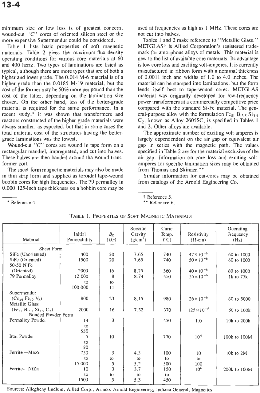
Table
1
lists basic properties of soft magnetic
materials. Table 2 gives the maximum-flux-density
operating conditions for various core materials at 60
and
400
hertz. Two types of laminations are listed as
typical, although there are more types that are of both
a
higher and lower grade. The
0.014
M-6 material is of a
higher grade than the
0.0185
M-19 material, but the
cost of the former may be 50% more per pound than the
cost of the latter, depending on the lamination size
chosen. On the other hand, less of the better-grade
material is required for the same performance. In a
recent study,* it was shown that transformers and
reactors constructed of the higher-grade materials were
always smaller,
as
expected, but that in some cases the
total material cost
of
the structures having the better-
grade laminations was the lowest.
Wound-cut
‘‘e”
cores are wound in tape form on a
rectangular mandrel, impregnated, and cut into halves.
These halves are then banded around the wound trans-
former coil.
The sheet-form magnetic materials may also be made
in thin strip form and supplied as toroidal tape-wound
bobbin cores for high frequencies. The
79
permalloy in
0.000
125-inch tape thickness on a bobbin core may be
-
*
Reference
4.
Material
used at frequencies as high as 1 MHz. These cores are
not cut into halves.
Tables
1
and
2
make reference to “Metallic Glass.”
METGLAS? is Allied Corporation’s registered trade-
mark for amorphous alloys of metals. This material is
new to the list of available core materials. Its advantage
is low core
loss
and exciting volt-amperes.
It
is currently
manufactured in ribbon form with a nominal thickness
of
0.0011
inch and widths of
1.0
to
4.0
inches. The
material can be stamped into laminations, but the form
lends itself best to tape-wound cores. METGLAS
material was originally developed for low-frequency
power transformers at a commercially competitive price
compared with the standard Si-Fe material. The gen-
eral-purpose alloy with the formulation Fesl
B,,,,
Si3.,
Cz, known as Alloy 2605SC, is specified in Tables
1
and 2. Other alloys are available.
The approximate number of exciting volt-amperes is
largely dependendent on the air gap or equivalent air
gap in series with the magnetic path. The values
specified in Table 2 are for the material exclusive of the
air gap. Information on core loss and exciting volt-
amperes for specific lamination sizes may be obtained
from Thomas and Skinner.**
Similar information for cut-cores may be obtained
from catalogs of the Arnold Engineering
Co.
Initial
Permeability
t
Reference
5.
**
Reference
6.
Sheet Form
SiFe (Unoriented)
SiFe (Oriented)
50-50
NiFe
(Oriented)
79
Permalloy
Supermendur
Metallic Glass
(cO49
Fe49
Vd
(Fe81
B13.5
c2)
Bonded Powder
Permalloy Powder
Iron
Powder
Ferrite-MnZn
Ferrite-NiZn
TABLE
1.
PROPERTIES
OF
SOFT
MAGNETIC MATERIALS
400
1500
2000
12
000
to
100
000
800
2000
14
to
550
5
to
80
750
to
15
000
10
to
1500
,
Form
Specific
Gravity
Curie
Temp.
(“C)
Operating
Resistivity Frequency
20
20
16
8
to
11
23
16
3
10
3
to
5
3
to
5
7.65
7.65
8.25
8.74
8.15
7.32
4.5
to
5.2
3.7
to
5.3
740
740
360
450
980
370
450
770
100
to
300
150
to
450
47x104
50X
lo-‘
40X
lo-‘
55X
26X10-6
125X
60
to
1000
60
to
1000
60
to
1000
lk
to
75k
60
to
5000
60
to
lOOk
I
l.O
I
lokto200k
I
lo4
lOOk
to
lOOM
I
::
I
lek
to
2M
100
106
200k
to
lOOM
Sources:
Allegheny
Ludlum, Allied Corp.,
Armco,
Arnold Engineering, Indiana General, Magnetics
MAGNETIC-CORE TRANSFORMERS AND REACTORS
Freq
.
(Hz)
60
60
60
60
60
400
400
400
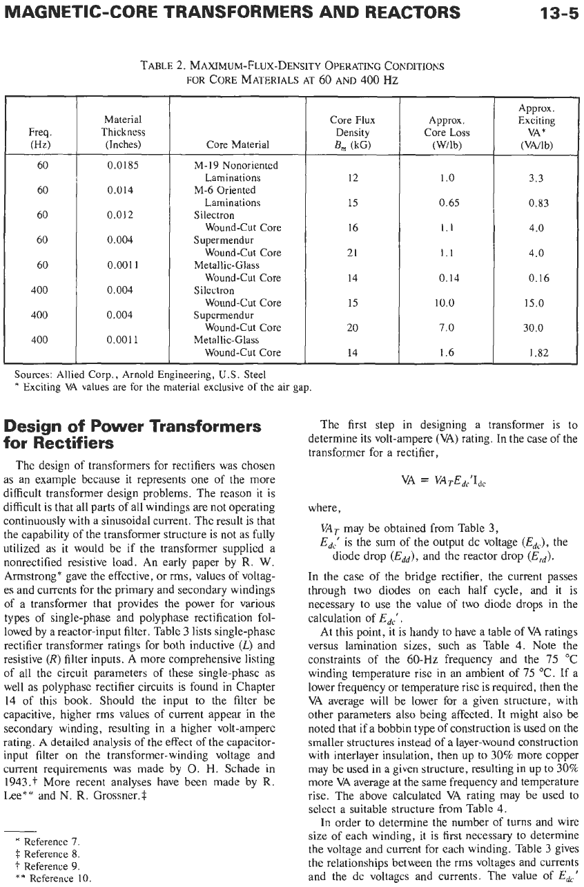
TABLE
2.
MAXIMUM-FLUX-DENSITY OPERATING CONDITIONS
FOR
CORE MATERIALS
AT
60
AND
400
HZ
Material
Thickness
(Inches)
0.0185
0.014
0.012
0.004
0.001
1
0.004
0.004
0.001
1
Core Material
M-19 Nonoriented
Laminations
M-6 Oriented
Laminations
Silectron
Wound-Cut Core
Supermendur
Wound-Cut Core
Metallic-Glass
Wound-Cut Core
Silectron
Wound-Cut Core
Supermendur
Wound-Cut Core
Metallic-Glass
Wound-Cut Core
Sources:
Allied
Corp.,
Arnold
Engineering,
U.S.
Steel
*
Exciting
VA
values
are
for
the
material
exclusive
of
the
air gap.
Design of Power Transformers
for Rectifiers
The design of transformers for rectifiers was chosen
as an example because it represents one of the more
difficult transformer design problems. The reason it is
difficult is that all parts of all windings
are
not operating
continuously with a sinusoidal current. The result is that
the capability of the transformer structure is not as fully
utilized as it would be if the transformer supplied a
nonrectified resistive load.
An
early paper by
R.
W.
Armstrong* gave the effective, or rms, values of voltag-
es and currents for the primary and secondary windings
of a transformer that provides the power for various
types of single-phase and polyphase rectification fol-
lowed by a reactor-input filter. Table
3
lists single-phase
rectifier transformer ratings for both inductive
(L)
and
resistive (R) filter inputs.
A
more comprehensive listing
of all the circuit parameters of these single-phase as
well as polyphase rectifier circuits is found in Chapter
14
of this book. Should the input to the filter be
capacitive, higher rms values of current appear in the
secondary winding, resulting in a higher volt-ampere
rating.
A
detailed analysis of the effect
of
the capacitor-
input filter on the transformer-winding voltage and
current requirements was made by
0.
H.
Schade in
1943."
More recent analyses have been made by
R.
Lee** and
N.
R.
Gr0ssner.t
__
*
Reference
7.
i
Reference
8.
?
Reference
9.
**
Reference
10.
Core Flux
Density
B,
(kG)
12
15
16
21
14
15
20
14
Approx.
Core Loss
(Wilb)
1
.o
0.65
1.1
1.1
0.14
10.0
7.0
1.6
13-5
Approx
.
Exciting
VA*
(VNlb)
3.3
0.83
4.0
4.0
0.16
15.0
30.0
1.82
The first step in designing a transformer
is
to
determine its volt-ampere
(VA)
rating.
In
the case of the
transformer for a rectifier,
where,
VAT
may be obtained from Table
3,
Edc'
is the sum of the output dc voltage
(Edc),
the
diode drop (Edd), and the reactor drop (Erd).
In the case of the bridge rectifier, the current passes
through two diodes
on
each half cycle, and it is
necessary to use the value of two diode drops in the
calculation of
Edc'.
At this point, it is handy to have a table of
VA
ratings
versus lamination sizes, such as Table
4.
Note the
constraints of the 60-Hz frequency and the
75
"C
winding temperature rise in
an
ambient of
75
"C. If a
lower frequency or temperature rise is required, then the
VA
average will be lower for a given structure, with
other parameters also being affected. It might also be
noted that if a bobbin type of construction is used on the
smaller structures instead of a layer-wound construction
with interlayer insulation, then up to
30%
more copper
may be used in a given structure, resulting in up to
30%
more
VA
average at the same frequency and temperature
rise. The above calculated
VA
rating may be used to
select a suitable structure from Table
4.
In order to determine the number of turns and wire
size of each winding, it is first necessary to determine
the voltage and current for each winding. Table
3
gives
the relationships between the rms voltages and currents
and the dc voltages and currents. The value of Edc'
13-6
REFERENCE
DATA
FOR ENGINEERS
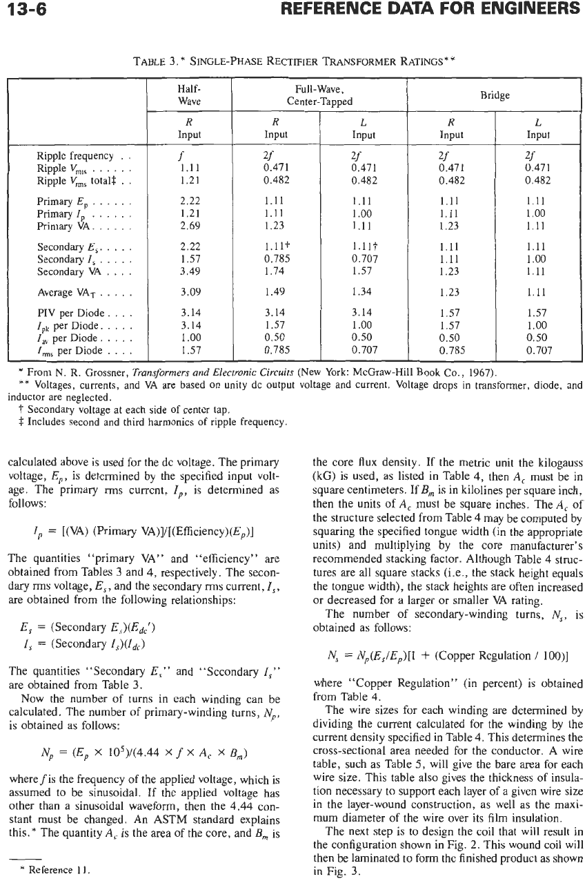
TABLE
3.
*
SINGLE-PHASE RECTIFIER TRANSFORMER RATINGS*
*
Half-
Wave
R
Input
Full-Wave
,
Center-Tapped
R
Input
Ripple frequency
.
.
Ripple
V,,
. .
. .
.
.
Ripple
V,,
total$.
. .
Primary
E,
.
.
.
. . .
Primary
I,
.
.
.
.
. .
Primary VA..
.
.
.
.
Secondary
E,.
. .
. .
Secondary
I,
.
.
.
.
.
Secondary
VA
.
. .
.
Average
VAT
.
.
.
.
.
PIV per Diode.
. .
.
I,,
per Diode.
.
. .
.
I,
per Diode.
. .
,
.
I,,
per Diode
. . .
.
f
1.11
1.21
2.22
1.21
2.69
2.22
1.57
3.49
3.09
3.14
3.14
1
.oo
1.57
2f
0.471
0.482
1.11
1.11
1.23
l.llt
0.785
1.74
1.49
3.14
1.57
0.50
0.785
__
L
Input
2f
0.471
0.482
1.11
1
.oo
1.11
l.llt
0.707
1.57
1.34
3.14
1
.oo
0.50
0.707
Bridge
R
Input
2f
0.471
0.482
1.11
1.11
1.23
1.11
1.11
1.23
1.23
1.57
1.57
0.50
0.785
*
From
N.
R. Grossner,
Transformers and Electronic Circuifs
(New York: McGraw-Hill
Book
Co.,
1967).
**
Voltages, currents,
and
VA
are based on unity dc output voltage
and
current. Voltage drops
in
transformer, diode,
and
7
Secondary voltage
at
each side of center tap.
f
Includes second and third harmonics
of
ripple frequency
inductor are neglected.
calculated above is used for the dc voltage. The primary
voltage,
E,,,
is determined by the specified input volt-
age. The primary
rms
current,
I,,,
is determined as
follows:
I,,
=
[(VA) (Primary
VA)]/[(Efficiency)(E,,)]
The quantities “primary VA” and “efficiency” are
obtained from Tables
3
and
4,
respectively. The secon-
dary rms voltage,
E,,
and the secondary rms current,
I,,
are obtained from the following relationships:
E,
=
(Secondary
,?,)(Edc‘)
I,
=
(Secondary
Is)(Idc)
The quantities “Secondary
E,”
and “Secondary
I,”
are obtained from Table
3.
Now the number of turns in each winding can be
calculated. The number of primary-winding turns,
Np,
is obtained as follows:
Np
=
(E,,
X
105)/(4.44
X
f
X
A,
X
B,)
wherefis the frequency
of
the applied voltage, which is
assumed to be sinusoidal. If the applied voltage has
other than a sinusoidal waveform, then the
4.44
con-
stant must be changed. An ASTM standard explains
this.* The quantity
A,
is the area of the core, and
B,,,
is
-
*
Reference
11
the core flux density. If the metric unit the kilogauss
(kG) is used, as listed in Table
4,
then
A,
must be in
square centimeters. If
B,
is in kilolines per square inch,
then the units of
A,
must be square inches. The
A,
of
the structure selected from Table
4
may be computed by
squaring the specified tongue width (in the appropriate
units) and multiplying by the core manufacturer’s
recommended stacking factor. Although Table
4
struc-
tures are
all
square stacks (Le., the stack height equals
the tongue width), the stack heights are often increased
or decreased for a larger or smaller VA rating.
The number of secondary-winding turns,
N,,
is
obtained as follows:
N,
=
N,,(E,/E,,)[I
+
(Copper Regulation
/
loo)]
where “Copper Regulation” (in percent)
is
obtained
from Table
4.
The wire sizes for each winding are determined by
dividing the current calculated for the winding by the
current density specified in Table
4.
This determines the
cross-sectional area needed for the conductor. A wire
table, such as Table
5,
will give the bare area for each
wire size. This table also gives the thickness of insula-
tion necessary to support each layer of a given wire size
in the layer-wound construction, as well as the maxi-
mum diameter of the wire over its film insulation.
The next step is to design the coil that will result in
the configuration shown in Fig.
2.
This wound coil will
then be laminated to form the finished product as shown
in Fig.
3.

3
E,
n
2
m
1
T5
h
0
31
m
1
2
v)
75
Y4
0.237 20.3 14.2
3
480 73.2 0.88 6.6 32.6 0.63 0.182
31
3
87
%
0.441 40.0 14.4
3
040
80.9 1.47 8.7 22
1
.oo
0.32
m
100
1
0.750 72.5 14.6 2 580 84.5 2.3
11.0
15.1 1.49
0.46
2.91
1
.o
31
125
1%
1.825 163 14.8 2 220 88.6 4.7 16.2 9.9
138
1
3/s
2.66 229 14.8 2 130 90.2 6.2 19.0 8.3 3.88 1.44
ua
P
150
1
Y2
3.80 298 14.8 2
000
91
.O
8.1 21.8 7.3 5.05 1.75
2
175
1%
7.0
524 14.8
1
845 92.8 12.8 27.8 5.3 8.0 2.86
212 2% 15.3
1
050 14.8
1
550 94.7 22.6 37.4 3.6 14.2 5.18
U
250 2% 29.3
1
823 14.8
1
335
95.7
35.5
41.5 2.6 22.2 8.5
31
25
1
2% 68.8 3 551 14.8 935 96.5 49.8 79.2 2.23
31.1
26.6
c)
31
v)
TABLE
4.*
VA
RATINGS
vs
LAMINATION
SIZES-60
Hz,
75
"C
TEMPERATURE
RISE**
5
625
36
0.114 9.1 14.0 4 060 63.5 0.5 4.7 52 0.37 0.098
6
Lamination Tongue Flux Current
Effi-
Core Copper Copper Weight, lb
E-I
Width, Area VA Density, Density, ciency,
Loss,
Loss,
Regulation,
Type in Product Average Kilogauss .Win2
%
Watts Watts
%
Iron Copper
*
Electm-Echnol.,
Vol.
67,
No.
1,
p.
61,
January,
1961.
Copyright C-M Technical Publications Corp.,
1961.
**
Table based on
29-gauge,
grain-oriented
(M6)
silicon steel, square stack. Exciting VNinput VA is
23.5
percent
(EI625)
to
12.7
percent
(EI251).
Operating temperature
=
75
"C
(amb)
+
75
"C (rise)
=
150
"C.
Copper weight will ordinarily be less than values in the table.
d
13-8
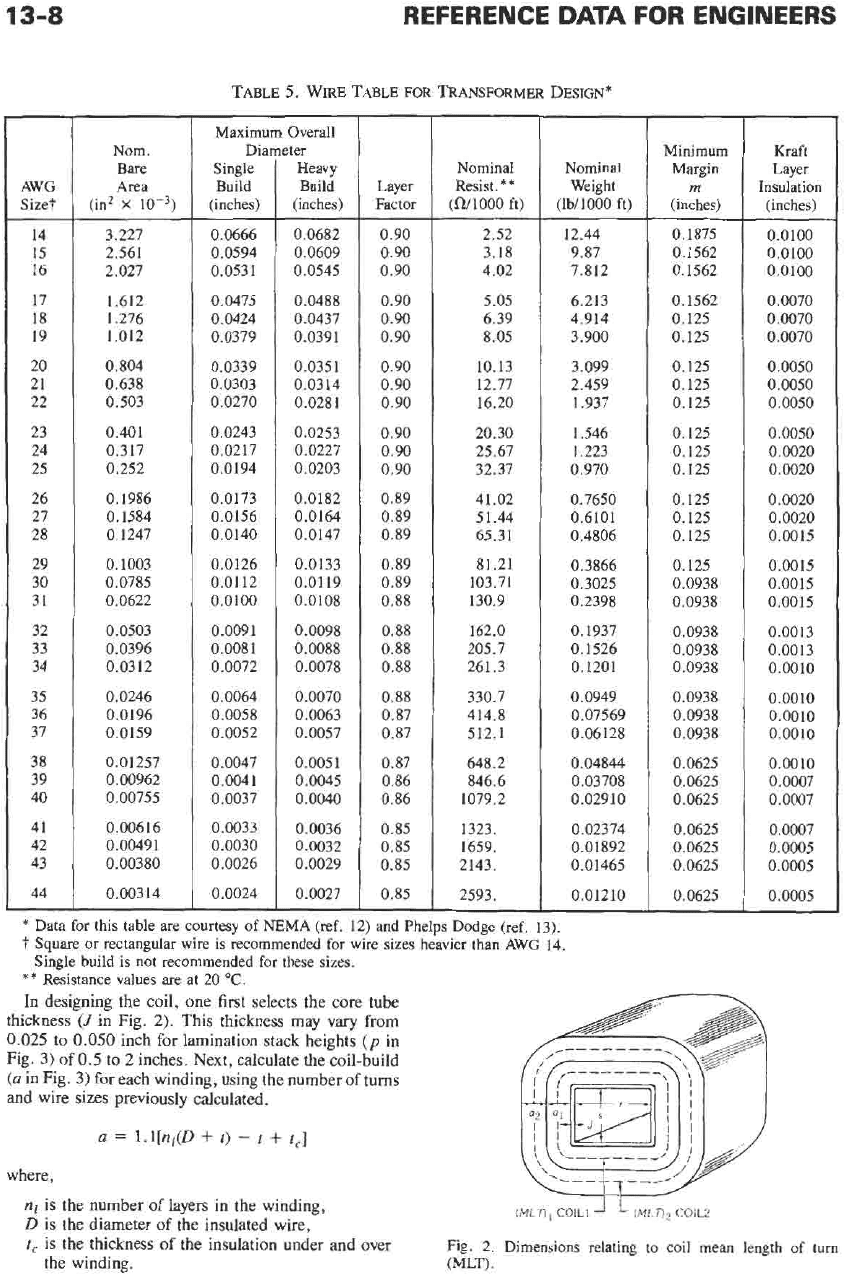
TABLE
5.
WIRE
TABLE
FOR
TRANSFORMER
DESIGN*
AWG
Size?
14
15
16
17
18
19
20
21
22
23
24
25
26
21
28
29
30
31
32
33
34
35
36
37
38
39
40
41
42
43
44
-
Nom.
Bare
Area
(in2
x
3.227
2.561
2.027
1.612
1.276
1.012
0.804
0.638
0.503
0.401
0.317
0.252
0.1986
0.1584
0.1247
0.1003
0.0785
0.0622
0.0503
0.0396
0.0312
0.0246
0.0196
0.0159
0.01257
0.00962
0.00755
0.00616
0.0049 1
0.00380
0.00314
Maximum Overall
DiaI
Single
Build
(inches)
0.0666
0.0594
0.0531
0.0475
0.0424
0.0379
0.0339
0.0303
0.0270
0.0243
0.0217
0.0194
0.0173
0.0156
0.0140
0.0126
0.0112
0.0100
0.0091
0.0081
0.0072
0.0064
0.0058
0.0052
0.0047
0.0041
0.0037
0.0033
0.0030
0.0026
0.0024
ter
Heavy
Build
(inches)
0.0682
0.0609
0.0545
0.0488
0.0437
0.0391
0.0351
0.0314
0.0281
0.0253
0.0227
0.0203
0.0182
0.0164
0.0147
0.0133
0.0119
0.0108
0.0098
0.0088
0.0078
0.0070
0.0063
0.0057
0.0051
0.0045
0.0040
0.0036
0.0032
0.0029
0.0027
Layer
Factor
0.90
0.90
0.90
0.90
0.90
0.90
0.90
0.90
0.90
0.90
0.90
0.90
0.89
0.89
0.89
0.89
0.89
0.88
0.88
0.88
0.88
0.88
0.87
0.87
0.87
0.86
0.86
0.85
0.85
0.85
0.85
Nominal
Resist.**
(a/looo
ft)
2.52
3.18
4.02
5.05
6.39
8.05
10.13
12.77
16.20
20.30
25.67
32.37
41.02
5 1.44
65.31
81.21
103.71
130.9
162.0
205.7
261.3
330.7
414.8
512.1
648.2
846.6
1079.2
1323.
1659.
2143.
2593.
Nominal
Weight
(lbi1000 ft)
12.44
9.87
7.812
6.213
4.914
3.900
3.099
2.459
1.937
1.546
1.223
0.970
0.7650
0.6101
0.4806
0.3866
0.3025
0.2398
0.1937
0.1526
0.1201
0.0949
0.07569
0.06 128
0.04844
0.03708
0.029 10
0.02374
0.01892
0.0 1465
0.01210
Minimum
Margin
m
(inches)
0.1875
0.1562
0.1562
0.1562
0.125
0.125
0.125
0.125
0.125
0.125
0.125
0.125
0.125
0.125
0.125
0.125
0.0938
0.0938
0.0938
0.0938
0.0938
0.0938
0.0938
0.0938
0.0625
0.0625
0.0625
0.0625
0.0625
0.0625
0.0625
Kraft
Layer
Insulation
(inches)
~
0.0100
0.0100
0.0100
0.0070
0.0070
0.0070
0.0050
0.0050
0.0050
0.0050
0.0020
0.0020
0.0020
0.0020
0.0015
0.0015
0.0015
0.0015
0.0013
0.0013
0.0010
0.0010
0.0010
0.0010
0.0010
0.0007
0.0007
0.0007
0.0005
0.0005
0.0005
*
Data for this table are courtesy of NEMA (ref.
12)
and Phelps Dodge (ref.
13).
7
Square
or rectangular wire is recommended for wire sizes heavier than AWG
14.
**
Resistance values
are
at
20
"C.
In
designing the coil, one first selects the core tube
thickness
(1
in Fig.
2).
This thickness may vary from
0.025
to
0.050
inch for lamination stack heights
(p
in
Fig.
3)
of
0.5
to
2
inches. Next, calculate
the
coil-build
(a
in Fig.
3)
for each winding, using the number of turns
and wire sizes previously calculated.
Single build is not recommended for these sizes.
a
=
l.l[q(D
+
t)
-
t
+
t,]
where,
nl
is
the number
of
layers in the winding,
D
is the diameter of the insulated wire,
t,
is
the thickness
of
the insulation under and over Fig.
2.
Dimensions relating to coil mean length of turn
the winding. (MLT)
,
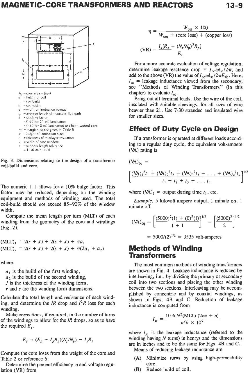
MAGNETIC-CORE TRANSFORMERS AND REACTORS
13-9
A,
=
core area
=
(gp)
k
o
=height
of
coil
=
coil-build
b
=toil
u,idth
g
=width
of
lamination
tongue
IC
=average
length
of
magnetic.flux
path
k
=stacking factor
=
0
90
for
14-mil lamination
=O
80
for
2-mil lamination
or
ribbon-wound core
m
=marginal
space given
in
Table
5
p =height
of
laminatinn stack
t
=thickness
of
interlayer
insulation
LL’
=width
of
core window
i
=window length tolerance
=
1116 Inch. total
Fig.
3.
Dimensions relating to
the
design of a transformer
coil-build
and
core.
The numeric
1.1
allows for a
10%
bulge factor. This
factor may be reduced, depending
on
the winding
equipment and methods of winding used. The total
coil-build should not exceed
85-90%
of the window
width.
Compute the mean length per turn (MLT) of each
winding from the geometry of the core and windings
(Fig.
2).
(MLT),
=
2(r
+
J)
+
2(s
+
J)
+
TTU~
(MLT),
=
2(r
+
J)
+
2(s
+
J)
+
.rr(2~l
+
(12)
where,
a,
is the build of the first winding,
a’
is the build of the second winding,
J
is the thickness of the winding form,
I
and
s
are
the winding-form dimensions.
Calculate the total length and resistance of each wind-
ing, and determine the
IR
drop and IZR loss for each
winding.
Make corrections,
if
required,
in
the
number
of
turns
of the windings to allow for the IR drops,
so
as to have
the required
E,.
Compute the core loses from the weight of the core and
Table
2
or reference
6.
Determine the percent efficiency
7
and voltage regu-
lation (VR) from
w,,
x
100
’
=
w,,,
+
(core
loss)
+
(copper loss)
For a more accurate evaluation of voltage regulation,
determine leakage-reactance drop
=
Idc
d,,
/27r,
and
add to the above (VR) the value of
IdCW~,/2TTEdc.
Here,
l,,
=
leakage inductance viewed from the secondary;
see “Methods of Winding Transformers” (in this
chapter) to evaluate
l,,
.
Bring out all terminal leads. Use the wire of the coil,
insulated with suitable sleevings, for all sizes of wire
heavier than 21. Use
7-30
stranded and insulated wire
for smaller sizes.
Effect of Duty Cycle on Design
If
a transformer is operated at different loads accord-
ing to a regular duty cycle, the equivalent volt-ampere
(VA) rating is
where (VA),
=
output during time
tl,
etc.
minute
off.
Example:
5
kilovolt-ampere output,
1
minute
on,
1
(5000)’(1)
+
(0)’(1)
=
5000/(2)”’
=
3535
volt-amperes
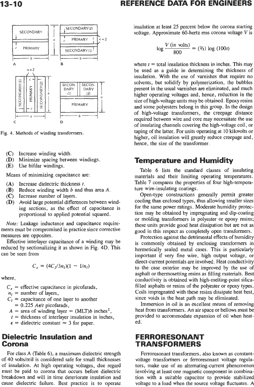
Methods of Winding
Transformers
The most common methods of winding transformers
are shown in Fig.
4.
Leakage inductance is reduced by
interleaving, Le., by dividing the primary or secondary
coil into two sections and placing the other winding
between the two sections. Interleaving may be accom-
plished by concentric and by coaxial windings, as
shown in Figs.
4B
and
C.
Reduction of leakage
inductance is computed from
10.6
N~(MLT) (2nc
+
U)
I,
=
n’b
X
lo9
where
I,
is the leakage inductance (referred to the
winding having N turns) in henrys and the dimensions
are in inches and to be the same for Figs.
4B
and C.
Means
of
reducing leakage inductance
are:
(A)
(B)
Reduce build of coil.
Minimize turns by using high-permeability
core.
13-10
SECONDARY
12)
t
PRIMARY
c
REFERENCE DATA FOR ENGINEERS
\
n=2
SECONDARY
bl
1-n-
C
T
I
l-
b+
B
[
-
I
(""[
t---b----l
D
Fig.
4.
Methods
of
winding transformers.
(C)
Increase winding width.
(D)
Minimize spacing between windings.
(E)
Use bifilar windings.
Means of minimizing capacitance are:
(A)
Increase dielectric thickness
t.
(B)
Reduce winding width
b
and thus area
A.
(C)
Increase number of layers.
(D)
Avoid large potential differences between wind-
ing sections, as the effect of capacitance is
proportional to applied potential squared.
Note:
Leakage inductance and capacitance require-
ments must be compromised in practice since corrective
measures
are
opposites.
Effective interlayer capacitance of a winding may be
reduced by sectionalizing it as shown in Fig.
4D.
This
can be seen from
C,
=
(4C1/3n1)(1
-
lhl)
where,
C,
=
effective capacitance in picofarads,
nl
=
number of layers,
CI
=
capacitance of one layer to another
A
=
area of winding layer
=
(MLT)b inches2,
t
=
thickness of interlayer insulation in inches,
E
=
dielectric constant
J
3
for paper.
=
0.225
A&
picofarads,
Dielectric Insulation and
Corona
For class
A
(Table 6), a maximum dielectric strength
of
40
volts/mil is considered safe for small thicknesses
of insulation. At high operating voltages, due regard
must be paid to corona that occurs before dielectric
breakdown and will in time deteriorate insulation and
cause dielectric failure. Best practice is to operate
insulation at least
25
percent below the corona starting
voltage. Approximate 60-hertz rms corona voltage
V
is
V
(in volts)
=
(34)
log
(loot)
log
800
where
t
=
total insulation thickness in inches. This may
be used as a guide in determining the thickness of
insulation. With the use of varnishes that require no
solvents, but solidify by polymerization, the bubbles
present in the usual varnishes
are
eliminated, and much
higher operating voltages and, hence, reduction in the
size of high-voltage units may be obtained. Epoxy resins
and some polyesters belong in this group. In the design
of high-voltage transformers, the creepage distance
required between wire and core may necessitate the use
of insulating channels covering the high-voltage coil, or
taping of the latter. For units operating at 10 kilovolts or
higher, oil insulation will greatly reduce creepage and,
hence, the size of the transformer.
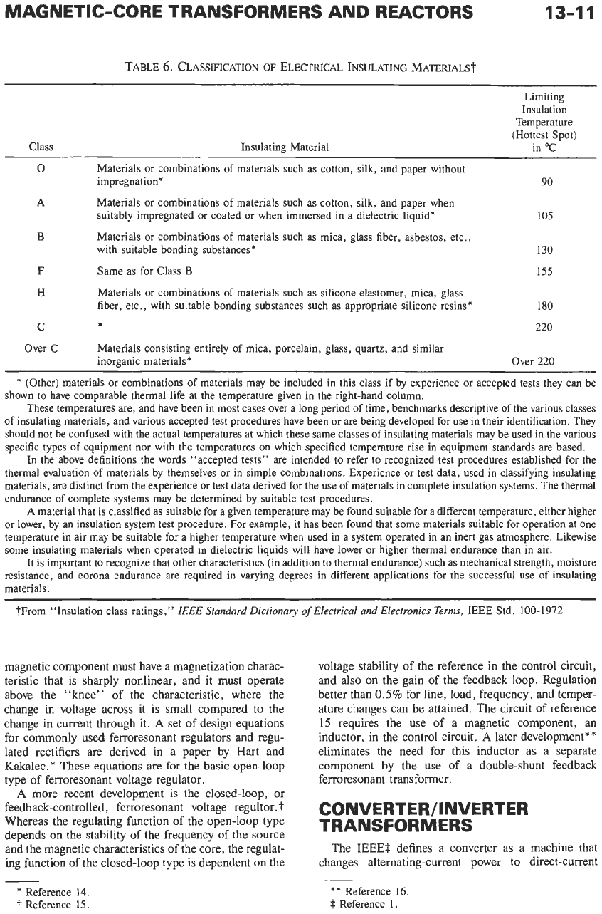
Temperature and Humidity
Table 6 lists the standard classes of insulating
materials and their limiting operating temperatures.
Table
7
compares the properties of four high-tempera-
ture wire-insulating coatings.
Open-type constructions generally permit greater
cooling than enclosed types, thus allowing smaller sizes
for the same power ratings. Moderate humidity protec-
tion may be obtained by impregnating and dip-coating
or molding transformers in polyester or epoxy resins;
these units provide good heat dissipation but are not as
good in this respect as completely open transformers.
Protection against the detrimental effects of humidity
is commonly obtained by enclosing transformers in
hermetically sealed metal cases. This is particularly
important if very fine wire, high output voltage, or
direct-current potentials are involved. Heat conductivity
to the case exterior may be improved by the use of
asphalt or thermosetting resins as filling materials. Best
conductivity is obtained with high-melting-point silica-
filled asphalts or resins
of
the polyester or epoxy types.
Coils impregnated with these resins dissipate heat best,
since voids in the heat path may be eliminated.
Immersion in oil is an excellent means of removing
heat from transformers.
An
air space or bellows must be
provided to accommodate expansion of oil when heat-
ed.
FERRORESONANT
TRANSFORMERS
Ferroresonant transformers, also known as constant-
voltage transformers or ferroresonant voltage regula-
tors, make use of an alternating-current phenomenon
involving at least one magnetic component in combina-
tion with a suitable capacitor to provide stabilized
voltage to a load when the source voltage fluctuates.
A
MAGNETIC-CORE TRANSFORMERS
AND
REACTORS
13-11
TABLE
6.
CLASSIFICATION
OF
ELECTRICAL
INSULATING MATERIALSt
Limiting
Insulation
Temperature
(Hottest Spot)
Class Insulating Material in “C
0
Materials or combinations of materials such as cotton, silk, and paper without
impregnation*
90
Materials or combinations of materials such as cotton, silk, and paper when
suitably impregnated or coated
or
when immersed in a dielectric liquid’
Materials or combinations of materials such as mica, glass fiber, asbestos, etc.,
with suitable bonding substances*
130
F
Same as for Class
B
155
H
A
105
B
Materials or combinations of materials such as silicone elastomer, mica, glass
fiber, etc., with suitable bonding substances such as appropriate silicone resins* 180
*
220
Materials consisting entirely of mica, porcelain, glass, quartz, and similar
inorganic materials*
C
Over C
Over
220
*
(Other) materials or combinations of materials may be included in this class if by experience or accepted tests they can be
shown to have comparable thermal life at the temperature given in the right-hand column.
These temperatures are, and have been in most cases over a long period of time, benchmarks descriptive of the various classes
of insulating materials, and various accepted test procedures have been or are being developed for
use
in their identification. They
should not be confused with the actual temperatures at which these
same
classes of insulating materials may be used in the various
specific types of equipment nor with the temperatures on which specified temperature rise in equipment standards are based.
In the above definitions the words “accepted tests” are intended to refer to recognized test procedures established for the
thermal evaluation of materials by themselves or in simple combinations. Experience or test data, used in classifying insulating
materials, are distinct from the experience or test data derived for the use of materials in complete insulation systems. The thermal
endurance of complete systems may be determined by suitable test procedures.
A
material that is classified as suitable for a given temperature may be found suitable for a different temperature, either higher
or
lower, by an insulation system test procedure. For example, it has been found that some materials suitable for operation at one
temperature in air may be suitable for a higher temperature when used in a system operated in an inert gas atmosphere. Likewise
some insulating materials when operated in dielectric liquids will have lower or higher thermal endurance than in air.
It is important to recognize that other characteristics (in addition to thermal endurance) such as mechanical strength, moisture
resistance, and corona endurance are required in varying degrees in different applications for the successful use of insulating
materials.
+From “Insulation class ratings,”
IEEE Standard Dictionary
of
Electrical and Electronics Terms,
IEEE Std.
100-1972
magnetic component must have
a
magnetization charac-
teristic that is sharply nonlinear,
and
it must operate
above the “knee” of the characteristic, where
the
change in voltage
across
it is small compared
to
the
change
in
current through it.
A
set of design equations
for commonly used ferroresonant regulators and regu-
lated rectifiers
are
derived in
a
paper
by
Hart and
Kakalec.*
These equations
are
for the basic open-loop
type of ferroresonant voltage regulator.
A
more
recent development is the closed-loop, or
feedback-controlled, ferroresonant voltage regultor.?
Whereas the regulating function of the open-loop type
depends
on
the stability of the frequency of the source
and the magnetic characteristics of the core, the regulat-
ing function of the closed-loop type is dependent
on
the
voltage stability of the reference in the control circuit,
and also
on
the gain of the feedback loop. Regulation
better than
0.5%
for line, load, frequency,
and
temper-
ature changes can be attained. The circuit of reference
15
requires the use of a magnetic component, an
inductor, in the control circuit.
A
later development**
eliminates the need for this inductor
as
a separate
component by the use of a double-shunt feedback
ferroresonant transformer.
CONVERTER/INVERTER
TRANSFORMERS
The
IEEE$
defines a converter as a machine that
changes alternating-current power to direct-current
*
Reference
14.
t
Reference
15.
**
Reference 16
$
Reference
1.