Middleton W.M. (ed.) Reference Data for Engineers: Radio, Electronics, Computer and Communications
Подождите немного. Документ загружается.

13-12
REFERENCE
DATA
FOR ENGINEERS
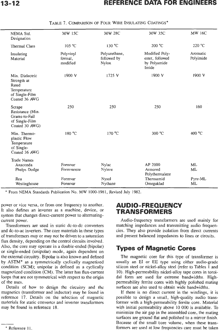
TABLE 7. COMPARISON
OF
FOUR
WIRE INSULATING COATINGS"
NEMA Std. MW 15C MW 28C
MW
35C
MW
16C
Designation
Thermal Class 105
"C
130
"C
200
"C 220 "C
Aromatic
Insulating Polyvinyl Polyurethane, Modified Poly-
Material formal, followed
by
ester, followed Polyimide
modified Nylon by Polyamide
Imide
Min.
Dielectric 1900
V
1725
V
1900
V
1900
V
Strength at
Rated
Temperature
of Single-Film
Coated
36
AWG
Scrape
Resistance (Min.
Grams-to-Fail
of Single-Film
Coated
30
AWG)
Min. Thermo-
plastic Flow
Temperature
of
Single-
Coated 36 AWG
250
180
"C
250
170 "C
250
300
"C
160
400
"C
Trade
Names
Anaconda Formvar Nylac
AP 2000 ML
Phelps Dodge Formvareze
Nyleze Armored ML
Rea
Formvar
Nysol Thermamid
Pyre-ML
Westinghouse Formvar Nythane
Omegaklad ML
Polythermaleze
*
From NEMA Standards Publication
No. MW
1000-1981, Revised
July
1982.
power or vice versa, or from one frequency to another.
It also defines an inverter as a machine, device, or
system that changes direct-current power to altemating-
current power.
Transformers are used in static dc-to-dc converters
and dc-to-ac inverters. The core materials in these types
of
transformers may or may not be driven to a saturation
flux density, depending on the control circuits involved.
Also, the core may operate in a double-ended (bipolar)
or single-ended (unipolar) mode, again dependent on
the external circuitry. Bipolar is also known and defined
by ASTM* as a symmetrically cyclically magnetized
condition (SCM); unipolar is defined as a cyclically
magnetized condition (CM). The latter has flux-current
loops that are not symmetrical with respect to the origin
of the axes.
Details of how to design the circuitry and the
magnetics (transformer and inductor) may be found in
reference 17. Details on the selection of magnetic
materials for static converter and inverter transformers
may be found in reference 18.
*
Reference
11.
AUDIO-FREQUENCY
TRANSFORMERS
Audio-frequency transformers
are
used mainly for
matching impedances and transmitting audio frequen-
cies. They also provide isolation from direct currents
and present balanced impedances to lines or circuits.
Types
of
Magnetic
Cores
The magnetic core for this type of transformer is
usually an
E1
or
EE
type using either audio-grade
silicon steel
or
nickel-alloy steel (refer to Tables
1
and
10).
High-permeability nickel-alloy tape cores in toroi-
dal form are used for extreme bandwidths. High-
permeability ferrite cores with highly polished mating
surfaces are also used to obtain wide bandwidths.
If there is no direct current in the windings, it is
possible
to
design a small, high-quality audio trans-
former with a high-permeability ferrite core. Material
with initial permeability above 10
000
is available. To
minimize the air gap in the assembled core, the mating
surfaces are ground flat and polished
to
a mirror finish.
Because of the small tore volume, when these trans-
formers are used at low frequencies care must be taken
MAGNETIC-CORE TRANSFORMERS AND REACTORS
13-13
to avoid core saturation. The maximum flux density in
a
core is given by:
B,,
=
(3.49
X
lo6)
EIJNA,
where,
B,,
=
maximum flux density (gauss),
E
=
rms
volts,
f
=
frequency (hertz),
N
=
number of winding turns,
A,
=
cross section of core (square inches).
Design of Audio-Frequency
Transformers
Important Parameters-Important parameters are
generator and load impedances,
R,
and
R1,
respectively;
generator voltage
E,;
frequency band
to
be transmitted;
harmonic distortion; and operating voltages (for ade-
quate insulation). See Fig.
1.
Refer
to
the section on
power-transformer design for details about physical
design, cores, winding, and
so
forth.
Midband Frequencies-The relative low- and
high-frequency responses
are
taken with reference to
midband frequencies where
uE,,~/E,
=
[(l
+
R,/Rl)
+
Rl/a2Rl]-'
Low
Frequencies- At low frequencies, the equiva-
lent unity-ratio network of a transformer becomes
approximately as shown in Fig.
5.
Amplitude
=
[l
+
(Rfp,//Xm)2]1i'2
Phase angle
=
tan
-'(Rfpa/X,)
where,
Rfpa
=
(RlR2a2)/(Rl
+
R2a2)
R1
=
R,
+
R,
R2
==
R1
+
R,
x,
=
2$L,
In a good output transformer,
R,, R,,
and
R,
may be
neglected. In input or interstage transformers,
R,
may
be omitted.
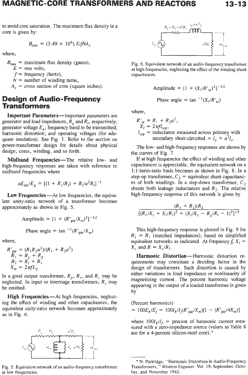
High Frequencies-.& high frequencies, neglect-
ing the effect of winding and other capacitances, the
equivalent unity-ratio network becomes approximately
as
in
Fig.
6.
Fig.
5.
Equivalent network of an audio-frequency transformer
at low frequencies.
I-
Fig.
6.
Equivalent network of
an
audio-frequency transformer
at high frequencies, neglecting the effect of the winding shunt
capacitances.
Amplitude
=
[l
+
(Xl/Rf,,)2]-1'2
Phase angle
=
tan
-'(Xl/RfSe)
where,
Rfse
=
Rl
+
R2a2,
Zscp
=
inductance measured across primary with
The low- and high-frequency responses are shown by
the curves of Fig.
7.
If at high frequencies the effect of winding and other
capacitances is appreciable, the equivalent network on a
1:l-turns-ratio basis becomes as shown in Fig.
8.
In a
step-up transformer,
C2
=
equivalent shunt capacitanc-
es of both windings. In a step-down transformer,
C2
shunts both leakage inductances and
R,.
The relative
high-frequency response of this network is given by
XI
=
2Tf4cp9
secondary short-circuited
=
1,
+
a2lS.
(R,
+
R,VR,
This high-frequency response is plotted in Fig.
9
for
R2
=
R,
(matched impedances), based on simplified
equivalent networks as indicated. At frequericyf,
Xl
=
X,
and
B
=
X,/Rl.
Harmonic
Distortion-Harmonic distortion re-
quirements may constitute a deciding factor in the
design of transformers. Such distortion is caused by
either variations in load impedance or nonlinearity of
magnetizing current. The percent harmonic voltage
appearing in the output of a loaded transformer is given
bY
(Percent harmonics)
=
lOOEh/Ef
=
lOOI~/Z&RrP,//X,)[l
-
(Rfpa/4X,)l
where
100Ih/If
=
percent of harmonic current mea-
sured with a zero-impedance source (values in Table
8
are for a 4-percent silicon-steel core).
*
*
N.
Partridge,
"Harmonic Distortion in Audio-Frequency
Transformers,"
Wireless Engineer,
Vol.
19;
September, Octo-
her, and November
1942.
13-14
REFERENCE
DATA
FOR ENGINEERS
I
I
I100
02
10
50
LOW-
MIDDLE
HIGH-
FREQUENCY RANGE FREQUENCY
RANGE RANGE
+R‘p
4cplR
se
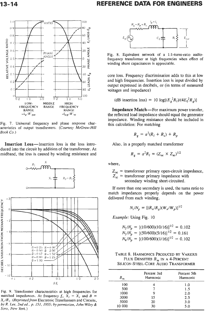
Fig.
7.
Universal frequency and phase response char-
acteristics of output transformers.
(Courtesy McGraw-Hill
Book
Co.)
Insertion
Loss-Insertion loss is the loss intro-
duced into the circuit by addition
of
the transformer. At
midband, the
loss
is
caused by winding resistance and
1
1
i
>
+2
5
s
U
=
0
U
-2
$
r
-4
B
Y
Z
-b
0
4
E=067
E=150
3
-8
9
-
10
c-121
I
I
I
I11111
\
1
i
w
0
1
02
05
10
20
Jlf,
Fig.
9.
Transformer characteristics at high frequencies for
matched impedances. At frequency
A,
X,
=
X,
and
B
=
XJR
,.
(Reprinted from
Electronic Transformers and Circuits,
byR. Lee, 2nded., p.
151,
1955;
by permission,
John
Wiley
&
Sons,
New
York.)
Fig.
8.
Equivalent network of a 1:l-turns-ratio audio-
frequency transformer at high frequencies when effect of
winding shunt capacitances is appreciable.
core loss. Frequency discrimination adds to this at low
and high frequencies. Insertion loss is input divided
by
output expressed in decibels, or
(in
terms of measured
voltages and impedance)
(dB insertion loss)
=
10
log[(E,2Rl)/(4E~R,)]
Impedance
Match-For maximum power transfer,
the reflected load impedance should equal the generator
impedance. Winding resistance should be included
in
this calculation: For matching
R,
=
a2(RI
+
R,)
+
R,
Also, in a properly matched transformer
R,
=
a2Rl
=
(Z,
X
Z,,)1/2
where,
Z,
=
transformer primary open-circuit impedance,
Z,,
=
transformer primary impedance with
secondary winding short-circuited.
If more than one secondary is used, the
turns
ratio to
match impedances properly depends on the power
delivered from each winding.
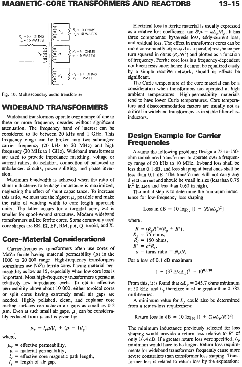
NJN,
=
[(R,,/R&WJW,)]
‘I2
Example: Using Fig.
10
NzIN,
=
[(10/600)(10/16)]’/*
=
0.102
N4/Np
=
[(100/600)(1/16)]”2
=
0.102
N3/N,
=
[(50/600)(5/16)]”2
=
0.161
TABLE
8.
HARMONICS PRODUCED
BY
VARIOUS
SILICON-STEEL-CORE AUDIO TRANSFORMER
FLUX
DENSITIES
B,
IN
A
‘&PERCENT
Percent 3rd Percent 5th
Bm
Harmonic Harmonic
100
4
1
.o
500
7
1.5
1000
9
2.0
3000
15
2.5
5000
20
3.0
10
000
30
5.0
MAGNETIC-CORE TRANSFORMERS AND REACTORS
13-15
R,
=
600
OHMS
IU,,
=
16
WATTS
Rq
=
100
OHMS
=
1
WATT
Fig.
10.
Multisecondary audio
transformer.
WIDEBAND TRANSFORMERS
Wideband transformers operate over a range of one to
three
or more frequency decades without significant
attenuation. The frequency band of interest can be
considered to lie between
20
kHz and
1
GHz. This
frequency range can be broken into two subranges:
carrier
frequency. (20
kHz
to 20 MHz) and high
frequmcy (20 MHz to
1
GHz)
.
Wideband transformers
are
used to provide impedance matching, voltage or
current ratios, dc isolation, connection of balanced to
unbalanced circuits, power splitting, and phase inver-
sion.
Maximum bandwidth is achieved when the ratio
of
shunt inductance to leakage inductance is maximized,
neglecting the effect of shunt capacitance. To increase
this
ratio,
we must use the highest
pe
possible and make
the
ratio of winding width to core length approach
unity.
The
latter occurs for a toroidal core, but is
smaller for spool-wound structures. Modem wideband
transformers utilize ferrite cores. Some commonly used
core shapes are
EE,
EI,
EP,
FW,
pot,
Q,
toroid, and X.
Core-Material Considerations
Carrier-frequency transformers often use cores of
MnZn ferrite having material permeability
(p)
in the
1OOO
to 20
000
range. High-frequency transfonpers
sometimes use NiZn ferrite cores having material per-
meability as low as
15,
especially when low core loss is
important. Most high-frequency transformers operate at
relatively low impedance levels.
To
obtain effective
permeability above about
10
OOO,
either toroidal cores
or split cores having extremely small air gaps
are
needed.
Highly polished, clean, and coplanar core
mating surfaces can achieve air
gaps
as
small as
0.2
pm.
Even at such small
air
gaps,
pe
can be considera-
bly reduced from
p
and is given by:
Pe
=
l,CJ[L
+
(P
-
W,I
where',
pe
=
effective permeability,
p
=
material permeability,
1,
=
effective core magnetic path length,
E,
=
length of air gap.
Electrical loss in ferrite material is usually expressed
as a relative loss coefficient, tan
8/p
=
dp/Rp.
It has
three
components: hysteresis loss, eddy-current
loss,
and residual loss. The effect in transformer cores can be
more conveniently expressed
as
a parallel resistance per
turn squared in
ohms
(R,/N2)
and plotted as a function
of frequency. Ferrite core loss
is
a frequency-dependent
nonlinear resistance; hence it cannot be equalized easily
by a simple reactive network, should its effects be
significant.
The Curie temperature of
the
core material can
be
a
consideration when transformers are operated at high
ambient temperatures. High-permeability materials
tend to have lower Curie temperatures. Core tempera-
ture and disaccommodation factors are usually not as
critical in wideband transformers as in stable filter-class
inductors.
Design Example for Carrier
Frequencies
Assume the following problem: Design a 75-to-150-
ohm
unbalanced transformer to operate over a frequen-
cy range of
50
kHz to
10
MHz. In-band loss shall be
less than
0.1
dB, and loss shaping at band ends shall be
less than
0.1
dB. The transformer will not carry any
direct current and should be small in size (less than 0.75
in2 in area and less than
0.60
in high).
The initial step
is
to determine the minimum induc-
tance for low-frequency loss shaping.
Loss
in dB
=
10
loglo
[I
+
(R/wL,)~]
where,
R
=
(R,R')I(R,
+
R'),
R,
=
75
ohms,
R'
=
a2R1,
Ri
=
150
ohms,
a
=
turns ratio
=
N,/N,
For a loss of
0.1
dB maximum
1
+
(37.5/WLP)2
=
100~'''O
From this, it is found that
d,
=
245.7
ohms
minimum
at
50
kHz, and
L,
therefore must be greater than
0.782
millihenries.
A minimum value for
L,
could also
be
determined
from
a
return-loss requirement:
Return
loss
in dB
=
10
loglo
[l
+
(~wL,/R')~]
The minimum inductance previously selected for
loss
shaping would provide a return loss relative to
R'
of
only
16.4
dB. If a greater return
loss
were specified,
Lp
minimum would have
to
be larger. Return-loss require-
ments for wideband transformers frequently cause more
severe constraints than transformer
loss
shaping. Trans-
former
loss
is related to return loss by the expression:
13-16
REFERENCE
DATA
FOR ENGINEERS
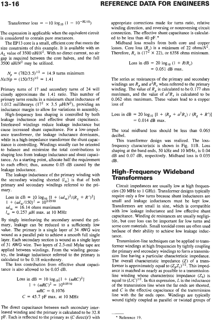
Transformer loss
=
-10 loglo (1
-
The expression is applicable when the equivalent circuit
is considered to contain pure reactances.
The EP13 core is
a
small, efficient core that meets the
size constraints of this example. It is available with an
A,
value of 3500 nWNZ. With no direct current,
no
air
gap
is
required between the core halves, and the full
3500 nWN’ may be utilized.
N,
=
(782/3.5)’/’
=
14.9 turns minimum
NslNp
=
(150/75)“2
=
1.41
Primary turns of
17
and secondary turns of 24 will
closely approximate the 1.41 ratio. This number of
primary
turns
results in a minimum shunt inductance of
1.012 millihenrys (17’
X
3.5 pWN2), providing
an
inductance margin to allow for variations in assembly.
High-frequency loss shaping is controlled by both
leakage inductance and effective shunt capacitance.
Interleaved windings reduce leakage inductance but
cause increased shunt capacitance. For a low-imped-
ance transformer, the leakage inductance dominates,
while in a high-impedance transformer the shunt capac-
itance
is
controlling. Windings usually can be oriented
to balance and minimize the total contributions to
shaping loss from leakage inductance and shunt capaci-
tance.
As
a
starting point, allocate half the requirement
to each effect; thus, assume
0.05
dB caused by the
leakage inductance.
The leakage inductance of the primary winding with
the secondary winding shorted
(Zsc)
is that of both
primary and secondary windings referred to the pri-
mary.
Loss
in dB
=
10 loglo
[l
+
(wl,)’/(R,
+
R‘)’]
wl,,
=
16.14 ohms maximum
I,,
=
0.257
pH
max. at 10 MHz
1
+
(Oi,,/i50)2
=
100.05/10
By singly interleaving the secondary around the pri-
mary, leakage can be reduced to a sufficiently low
value. The primary
is
a single layer of 34 AWG wire
wound as a parallel pair to achieve a smooth full single
layer. Each secondary section is wound as a single layer
of 31 AWG wire. Two layers
of
2.5-mil Mylar tape are
applied between windings. From the winding geome-
try,
the leakage inductance referred to the primary is
calculated to be
0.18
microhenry.
The loss contribution from effective shunt capaci-
tance is also allowed to be
0.05
dB.
Loss
in dB
=
10
log,o[l
+
(WRC)~]
oRC
=
0.1076
C
=
45.7 pF max. at 10 MHz
1
+
(WRC)~
=
100~05~10
The direct capacitance between each secondary inter-
leaved winding and the primary is calculated to be 32.8
pF. Each
is
reflected to the primary as
(C
direct)/3 with
appropriate corrections made for turns ratio, relative
winding direction, and reversing or nonreversing circuit
connection. The effective shunt capacitance is calculat-
ed to be less than 40 pF.*
Midband loss results from both core and copper
losses. Core loss
(R
)
is a minimum of 22 ohmslN’.
Therefore,
R,
is (17
f
X
22), or 6358 ohms minimum.
Loss
in dB
=
20 loglo (1
+
RIR,)
=
0.051 dB max.
The series ac resistances of the primary and secondary
windings are
R,
and
a2R,
when referred to the primary
winding. The value of
R,
is calculated to be 0.177 ohm
maximum, and the value of
a2R,
is calculated to be
0,062 ohm maximum.
These
values lead to a copper
loss of
Loss
in dB
=
20 loglo [l
+
(R,
+
&R,)
1
(R~
+
R‘)]
=
0.014 dB max.
The total midband loss should be less than 0.065
decibel.
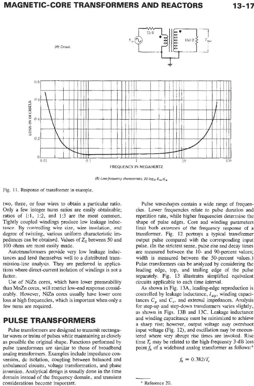
This transformer design was realized. The loss-
frequency characteristic is shown in Fig. 11B.
Loss
shaping at the band ends,
50
kHz and 10 MHz, is 0.04
dB and 0.07 dB, respectively. Midband loss is 0.035
dB
.
High-Frequency Wideband
Transformers
Circuit impedances are usually low at high frequen-
cies (20 MHz
to
1
GHz).
Transformer designs typically
require only a few turns because shunt inductances are
small and leakage inductances must be kept low.
Transformers are small in size, which is compatible
with low leakage inductance and low effective shunt
capacitance. Winding dc resistances are usually negligi-
ble, but core loss can be important for low turns and
some core materials. Small toroidal cores are often used
bec‘ause of their ability to achieve low leakage induc-
tance.
Transmission-line techniques can be applied to trans-
former windings at high Erequencies by tightly coupling
the primary and secondary windings
to
form
a
transmis-
sion line having
a
particular characteristic impedance.
The overall characteristic impedance
(Z)
of a trans-
former is approximately equal
to
(ZpZs)112.
This imped-
ance is matched as nearly as possible
to
a transmission-
line winding whose characteristic impedance
(Zo)
is
equal to
(L/C)”*.
In this expression,
L
is
the inductance
of
the transmission line when the far ends
are
shorted,
and
C
is the effective capacitance of the transmission
line with the far ends open. Windings are typically
wound tightly coupled as parallel or twisted groups of
*
Reference
19.
MAGNETIC-CORE TRANSFORMERS AND REACTORS
13-17
(AJ
Clrcuit.
FREQUENCY
IN
MEGAHERTZ
(E)
Loss-frequency characteristic,
20
loglo
Eou,iEhn
Fig.
11.
Response
of transformer
in
example.
two, three, or four wires to obtain a particular ratio.
Only a few integer turns ratios are easily obtainable;
ratios of 1:1, 1:2, and 1:3 are the most common.
Tightly coupled windings produce low leakage induc-
tance. By controlling wire size, wire insulation, and
degree of twisting, various uniform characteristic im-
pedances can be obtained. Values of
Zo
between
50
and
100 ohms are most easily made.
Autotransformers provide very low leakage induc-
tances and lend themselves well
to
a distributed trans-
mission-line analysis. They are preferred in applica-
tions where direct-current isolation of windings is not a
factor.
Use of NiZn cores, which have lower permeability
than MnZn cores, will restrict low-end response consid-
erably. However, NiZn cores usually have lower core
loss at high frequencies, which
is
important when only a
few turns are required.
PULSE TRANSFORMERS
Pulse transformers are designed to transmit rectangu-
lar waves or trains of pulses while maintaining as closely
as possible the original shape. Functions performed by
pulse transformers are similar to those of broadband
analog transformers. Examples include impedance con-
version, dc isolation, coupling between balanced and
unbalanced circuits, voltage transformation, and phase
inversion. Analytical design is usually done in the time
domain instead of the frequency domain, and transient
considerations become important.
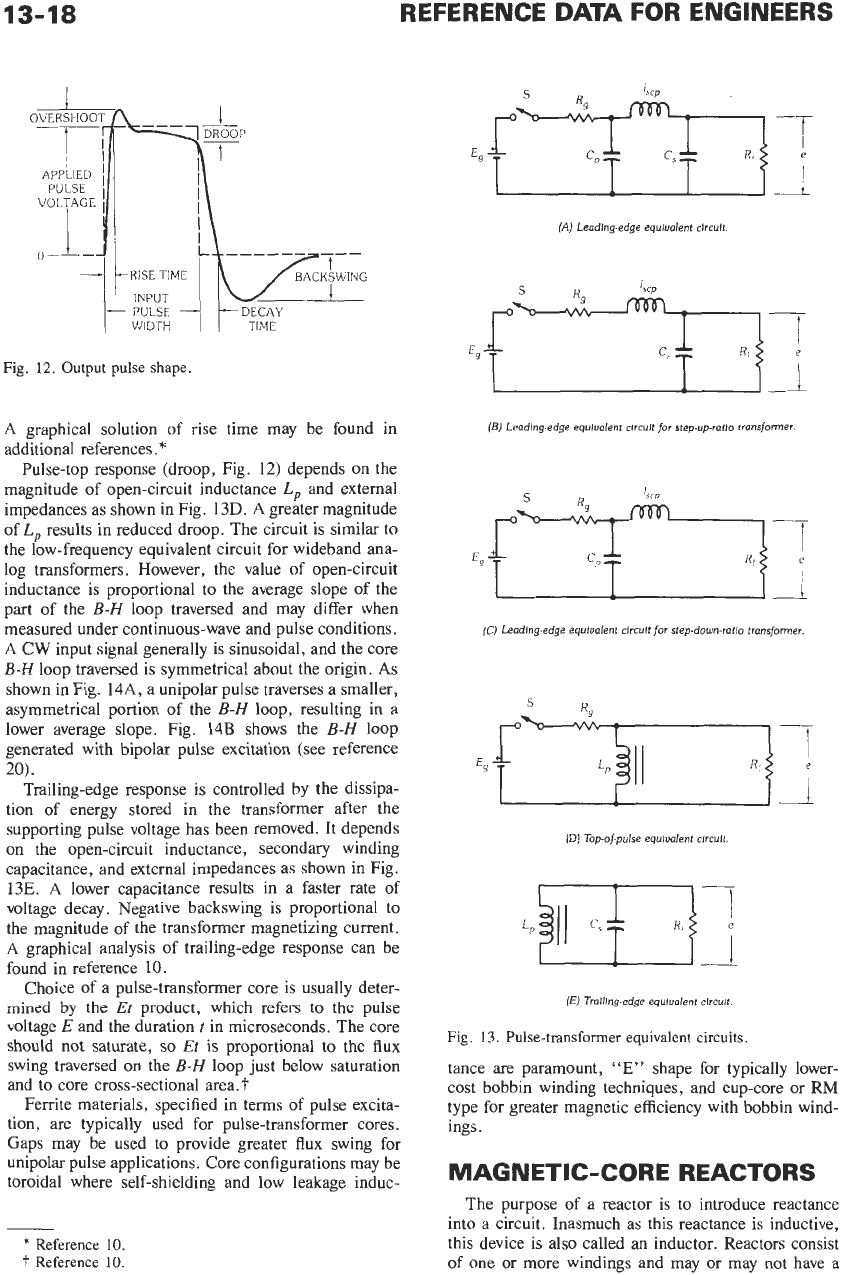
Pulse waveshapes contain a wide range of frequen-
cies. Lower frequencies relate to pulse duration and
repetition rate, while higher frequencies determine the
shape of pulse edges. Core and winding parameters
limit both extremes of the frequency response of a
transformer. Fig.
12
portrays a typical transformer
output pulse compared with the corresponding input
pulse. (In the strictest sense, pulse rise and decay times
are measured between the 10- and 90-percent values;
width is measured between the 50-percent values.)
Pulse transformers can be analyzed by considering the
leading edge, top, and trailing edge of the pulse
separately. Fig. 13 illustrates simplified equivalent
circuits applicable to each time interval.
As shown in Fig. 13A, leading-edge reproduction is
controlled by leakage inductance,
I,,
,
winding capaci-
tances
Cp
and
C,,
and external impedances. Analysis
for step-up and step-down transformers varies slightly,
as shown in Figs. 13B and 13C. Leakage inductance
and winding capacitance must be minimized to achieve
a sharp rise; however, output voltage may overshoot
input voltage (Fig. 12), and oscillation may be encoun-
tered where very abrupt rise times are invoked. Rise
time
T,
may be related to the high-frequency 3-dB loss
point
fh
of a wideband analog transformer as follows:*
fh
=
0.382lC
*
Reference
20.
13-18
REFERENCE
DATA
FOR ENGINEERS
PULSE
7
YD:IcM:\i
WIDTH
Fig.
12.
Output pulse shape.
A
graphical solution of rise time may be found in
additional references.
*
Pulse-top response (droop, Fig. 12) depends on the
magnitude of open-circuit inductance
L,
and external
impedances as shown in Fig.
13D.
A
greater magnitude
of
L,
results in reduced droop. The circuit is similar
to
the low-frequency equivalent circuit for wideband ana-
log transformers. However, the value of open-circuit
inductance is proportional to the average slope
of
the
part of the
B-H
loop traversed and may differ when
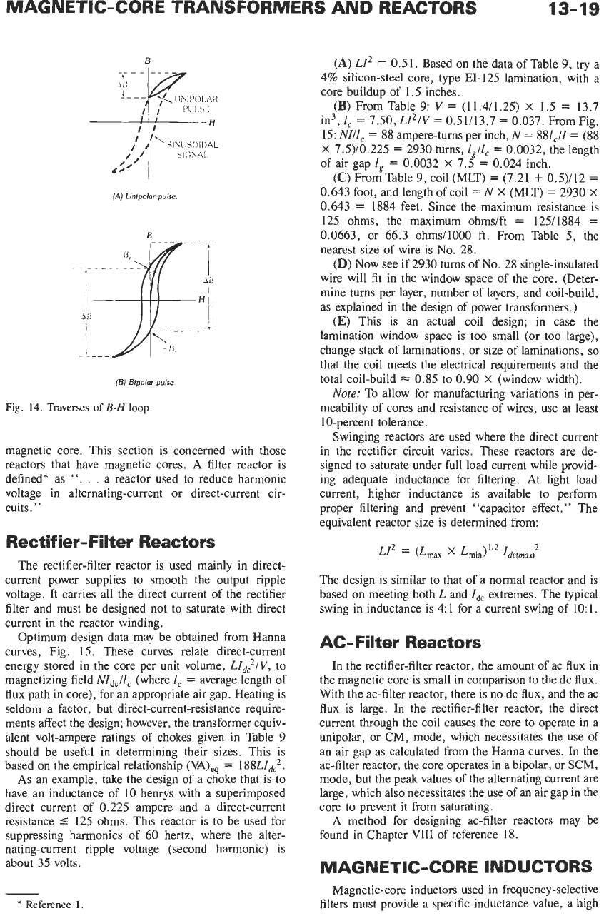
measured under continuous-wave and pulse conditions.
A
CW input signal generally is sinusoidal, and the core
B-H
loop traversed is symmetrical about the origin.
As
shown in Fig. 14A, a unipolar pulse traverses a smaller,
asymmetrical portion of the
B-H
loop, resulting in a
lower average slope. Fig.
14B
shows the
B-H
loop
generated with bipolar pulse excitation (see reference
20).
Trailing-edge response is controlled by the dissipa-
tion of energy stored in the transformer after the
supporting pulse voltage has been removed. It depends
on the open-circuit inductance, secondary winding
capacitance, and external impedances as shown in Fig.
13E.
A
lower capacitance results in a faster rate of
voltage decay. Negative backswing is proportional to
the magnitude of the transformer magnetizing current.
A graphical analysis of trailing-edge response can be
found in reference
10.
Choice of a pulse-transformer core is usually deter-
mined
by
the
Et
product, which refers
to
the pulse
voltage
E
and the duration
t
in microseconds. The core
should not saturate,
so
Et
is
proportional to the flux
swing traversed on the
B-H
loop just below saturation
and to core cross-sectional area.?
Ferrite materials, specified in terms of pulse excita-
tion, are typically used for pulse-transformer cores.
Gaps may be used to provide greater flux swing for
unipolar pulse applications. Core configurations may be
toroidal where self-shielding and low leakage induc-
*
Reference
10.
‘l
Reference
10.
(A)
Leading-edge equiualent clrcult
(E)
Leading-edge equiualent circuit for step-up-ratio transformer.
(C)
Leading-edge equiualent circult
for
stepdown-ratio transformer
(D)
Top-of-pulse equiualent circult
fEi
Trailing-edge equiuolent circuit
Fig.
13.
Pulse-transformer equivalent circuits
tance are paramount,
“E”
shape for typically lower-
cost bobbin winding techniques, and cup-core or RM
type for greater magnetic efficiency with bobbin wind-
ings.
MAGNETIC-CORE REACTORS
The purpose of a reactor is to introduce reactance
into a circuit. Inasmuch as this reactance is inductive,
this device is
also
called an inductor. Reactors consist
of one or more windings and may or may not have a
MAGNETIC-CORE TRANSFORMERS AND REACTORS
13-19
B
(AJ
Unlpolor
pulse.
B
(61
Blpolor
pulse
Fig.
14.
Traverses
of
B-H
loop.
magnetic core. This section is concerned with those
reactors that have magnetic cores.
A
filter reactor is
defined* as
“. .
.
a reactor used to reduce harmonic
voltage in alternating-current or direct-current cir-
cuits.”
Rectifier-Filter Reactors
The rectifier-filter reactor is used mainly in direct-
current power supplies to smooth the output ripple
voltage. It carries all the direct current of the rectifier
filter and must be designed not to saturate with direct
current in the reactor winding.
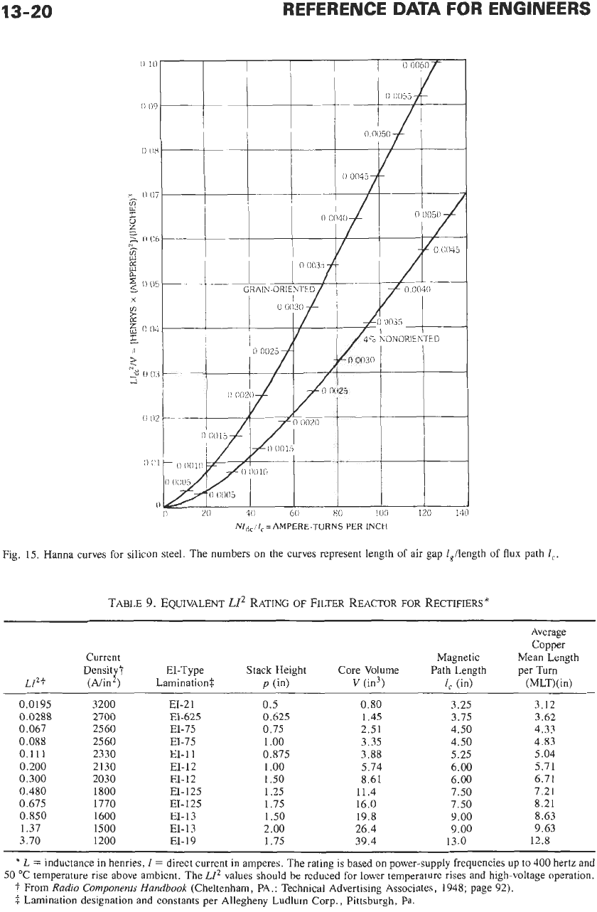
Optimum design data may be obtained from Hanna
curves, Fig.
15.
These curves relate direct-current
energy stored in the core per unit volume, LId:/v, to
magnetizing field
NZdc/lc
(where
I,
=
average length of
flux path in core), for an appropriate air gap. Heating is
seldom a factor, but direct-current-resistance require-
ments affect the design; however, the transformer equiv-
alent volt-ampere ratings of chokes given in Table 9
should be useful in determining their sizes. This is
based on the empirical relationship
(VA),q
=
188Lzd:.
As
an example, take the design
of
a choke that is to
have an inductance
of
10
henrys with a superimposed
direct current of 0.225 ampere and a direct-current
resistance
5
125 ohms. This reactor is to be used for
suppressing harmonics of 60 hertz, where the alter-
nating-current ripple voltage (second harmonic) is
about
35
volts.
(A)
LZ2
=
0.51. Based on the data of Table 9, try a
4% silicon-steel core, type EI-125 lamination, with a
core buildup of 1.5 inches.
(B)
From Table 9:
V
=
(11.4/1.25)
X
1.5
=
13.7
in3,
1,
=
7.50,
LI’IV
=
0.51113.7
=
0.037. FromFig.
15:
NI/l,
=
88 ampere-turns per inch,
N
=
881J
=
(88
X
7.5)/0.225
=
2930 turns,
l,llc
=
0.0032, the length
of air gap
I,
=
0.0032
X
7.5
=
0.024 inch.
(C)
From Table
9,
coil (MLT)
=
(7.21
+
0.5)/12
=
0.643 foot, and length of coil
=
N
X
(MLT)
=
2930
X
0.643
=
1884
feet. Since the maximum resistance is
125 ohms, the maximum ohmslft
=
125/1884
=
0.0663, or 66.3 ohms11000
ft.
From Table
5,
the
nearest size of wire is
No.
28.
(D)
Now see if 2930 turns of
No.
28 single-insulated
wire will fit in the window space of the core. (Deter-
mine turns per layer, number of layers, and coil-build,
as explained in the design of power transformers.)
(E)
This is an actual coil design; in case the
lamination window space is too small (or too large),
change stack of laminations, or size of laminations,
so
that the coil meets the electrical requirements and the
total coil-build
=
0.85 to 0.90
X
(window width).
Note:
To allow for manufacturing variations in per-
meability of cores and resistance of wires, use at least
10-percent tolerance.
Swinging reactors are used where the direct current
in the rectifier circuit varies. These reactors are de-
signed to saturate under full load current while provid-
ing adequate inductance for filtering. At light load
current, higher inductance is available to perform
proper filtering and prevent “capacitor effect.” The
equivalent reactor size is determined from:
LP
=
(L~~~
x
L~,~)~’~
1,,,2
The design is similar to that of a normal reactor and is
based on meeting both
L
and
Idc
extremes. The typical
swing in inductance is
4:
1 for a current swing of
10:
1.
AC-Filter Reactors
In the rectifier-filter reactor, the amount
of
ac flux in
the magnetic core is small in comparison to the dc flux.
With the ac-filter reactor, there is no dc flux, and the ac
flux is large. In the rectifier-filter reactor, the direct
current through the coil causes the core to operate in a
unipolar, or
CM,
mode, which necessitates the use of
an air gap as calculated from the Hanna curves. In the
ac-filter reactor, the core operates
in
a
bipolar,
or
SCM,
mode, but the peak values of the alternating current are
large, which also necessitates the use of an air gap in the
core to prevent it from saturating.
A
method for designing ac-filter reactors may be
found in Chapter VI11
of
reference
18.
MAGNETIC-CORE INDUCTORS
*
Reference
1.
Magnetic-core inductors used in frequency-selective
filters must provide a specific inductance value, a high
13-20
REFERENCE
DATA
FOR ENGINEERS
Fig.
15.
Hanna
curves for silicon steel. The numbers on the curves represent length of air gap l,/length
of
flux
path
1,.
TABLE
9.
EQUIVALENT
LIZ
RATING
OF
FILTER REACTOR
FOR
RECTIFIERS
*
Average
Copper
Current Magnetic Mean Length
Density?
EI-Type
Stack Height Core Volume Path Length per
Turn
LPf
(Aiin’) Lamination$
P
(in)
v
(in3)
4
(in) (MLT)(in)
0.0195 3200
0.0288 2700
0.067 2560
0.088
2560
0.111 2330
0.200 2130
0.300 2030
0.480 1800
0.675 1770
0.850 1600
1.37 1500
3.70 1200
EI-21
EI-625
EI-75
EI-75
EI-11
EI-12
EL12
EI-
125
EI- 125
EI-13
EI-
13
EI-19
0.5
0.625
0.75
1
.oo
0.875
1
.oo
1.50
1.25
1.75
1
SO
2.00
1
.I5
0.80
1.45
2.51
3.35
3.88
5.74
8.61
11.4
16.0
19.8
26.4
39.4
3.25
3.75
4.50
4.50
5.25
6.00
6.00
7.50
7.50
9.00
9.00
13.0
3.12
3.62
4.33
4.83
5.04
5.71
6.71
7.21
8.21
8.63
9.63
12.8
*
L
=
inductance in henries,
Z
=
direct current
in
amperes. The rating
is
based
on
power-supply frequencies up to
400
hertz and
50
“C temperature rise above ambient. The
LIZ
values should be reduced for lower temperature rises and high-voltage operation.
?
From
Radio
Components Handbook
(Cheltenham, PA.: Technical Advertising Associates,
1948;
page
92).
f
Lamination designation and constants per Allegheny Ludlum Corp., Pittsburgh,
Pa.
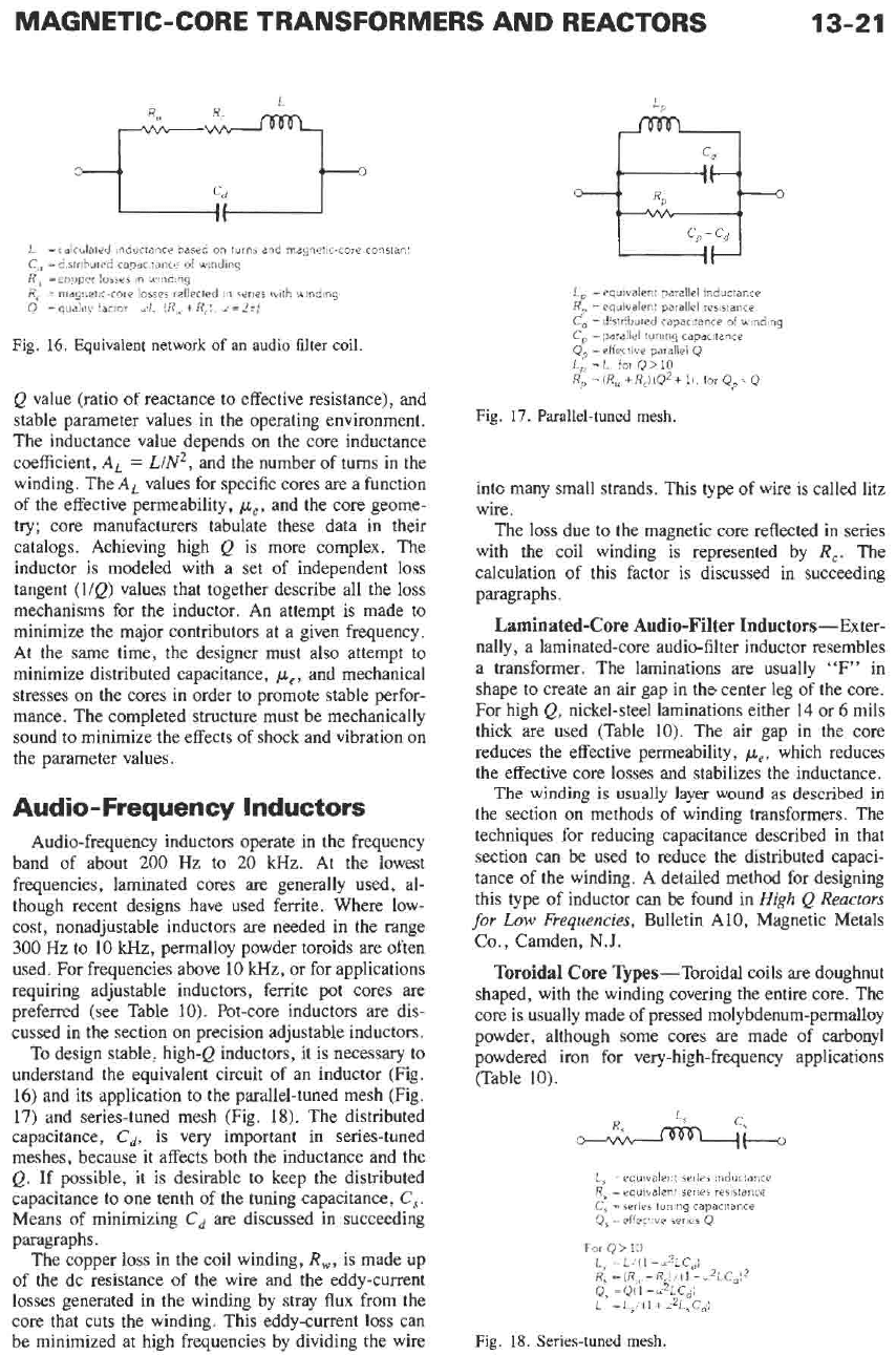
13-21
L
C,,
=
d.stributed capac
tance
of
wnding
R~,
=copper
losses
in
wnding
R,
=
magnetic-core losses
reflected
~n
series
iuith
binding
=
calciilated inductance basec
on
turns
and magnetic-core constant
Q
=quaiityiactor=Y~~. ~R,,.+R,I
d=~ri
Fig.
16.
Equivalent network
of
an
audio filter coil.
Q value (ratio of reactance to effective resistance), and
stable parameter values in the operating environment.
The inductance value depends on the core inductance
coefficient,
A,
=
L/N2,
and the number of turns in the
winding. The
AL
values for specific cores are a function
of the effective permeability,
pe,
and the core geome-
try; core manufacturers tabulate these data in their
catalogs. Achieving high Q is more complex. The
inductor is modeled with a set of independent loss
tangent (l/Q) values that together describe all the loss
mechanisms for the inductor. An attempt is made to
minimize the major contributors at a given frequency.
At the same time, the designer must also attempt to
minimize distributed capacitance,
pe
,
and mechanical
stresses on the cores in order to promote stable perfor-
mance. The completed structure must be mechanically
sound to minimize the effects of shock and vibration on
the parameter values.
Audio- Frequency Inductors
Audio-frequency inductors operate in the frequency
band of about 200 Hz to
20
kHz. At the lowest
frequencies, laminated cores are generally used, al-
though recent designs have used ferrite. Where low-
cost, nonadjustable inductors are needed in the range
300
Hz to 10 kHz, permalloy powder toroids are often
used. For frequencies above 10 kHz, or for applications
requiring adjustable inductors, ferrite pot cores are
preferred (see Table
10).
Pot-core inductors are dis-
cussed in the section on precision adjustable inductors.
To
design stable, high-Q inductors, it is necessary to
understand the equivalent circuit of an inductor (Fig.
16) and its application to the parallel-tuned mesh (Fig.
17)
and series-tuned mesh (Fig. 18). The distributed
capacitance,
cd,
is
very important in series-tuned
meshes, because it affects both the inductance and the
Q.
If
possible, it
is
desirable to keep the distributed
capacitance to one tenth of the tuning capacitance,
C,.
Means
of
minimizing
Cd
are discussed in succeeding
paragraphs.
The copper loss in the coil winding,
R,,
is made up
of the dc resistance of the wire and the eddy-current
losses generated in the winding by stray flux from the
core that cuts the winding. This eddy-current loss can
be minimized at high frequencies by dividing the wire
c,
-
Cd
L,
=equivalent
parallel
inductance
R, =equivalent parallel resisiance
Cd ~
d!str!buted capacitance
of
wndmg
C
=parallel
tuning
capacitance
Q’
=effective parallel
Q
L$=L.
for
Q>IO
R, =(R,+R,J(Q2+1i.
forQ,,=Q
Fig.
17.
Parallel-tuned mesh.
into many small strands. This type of wire is called litz
wire.
The loss due to the magnetic core reflected in series
with the coil winding is represented by
R,.
The
calculation of this factor is discussed in succeeding
paragraphs.
Laminated-Core Audio-Filter Inductors-Exter-
nally
,
a laminated-core audio-filter inductor resembles
a transformer. The laminations are usually “F” in
shape to create an air gap in the center leg of the core.
For high Q, nickel-steel laminations either
14
or 6 mils
thick are used (Table
10).
The air gap in the core
reduces the effective permeability,
pe,
which reduces
the effective core losses and stabilizes the inductance.
The winding is usually layer wound as described in
the section on methods of winding transformers. The
techniques for reducing capacitance described in that
section can be used to reduce the distributed capaci-
tance of the winding. A detailed method for designing
this type of inductor can be found in
High
Q
Reactors
for
Low
Frequencies,
Bulletin A10, Magnetic Metals
Co.,
Camden,
N.J.
Toroidal
Core
Types-Toroidal coils
are
doughnut
shaped, with the winding covering the entire core. The
core is usually made of pressed molybdenum-permalloy
powder, although some cores are made of carbonyl
powdered iron for very-high-frequency applications
(Table 10).
L,
=
ec;uiualer.t
series
mductance
R,
=
equibalent sene5 resistance
C,
=series
tuning
capacitance
Q,
=effective
series
Q
For
Q
>
10
L, =LI(l-d~LCdl
R,
=(R!,.-R
~/(l-w2LC,)*
0.
=
Q(l
-
~&_Cii
Fig.
18.
Series-tuned mesh.