Middleton W.M. (ed.) Reference Data for Engineers: Radio, Electronics, Computer and Communications
Подождите немного. Документ загружается.

13-22
TABLE
10.
CHARACTERISTICS
OF
SOME
CORE
MATERIALS
FOR
AUDIO-FILTER
COILS
Eddy-
Initial Hysteresis Residual Current
Perme- Resistiv- Coef- Coef- Coef- Application and
Material ability ity ficient ficient ficient Gauge Frequency Range
(Po) (ohm-cmj
(aX106j
(cX106)
(ex
lo9)
(mils) (kilohertz)
or Alloy
4%
silicon steel
Low nickel
High nickel
Molybdenum
permalloy powder
Carbonyl types:
C
P
Th
Ferrites$:
3B7
3B9
3D3
4c4
400 60X10-6
3:?
}
44X10m6
10
000
lopoo0
}
57X10-6
20
000
550t
1.0
200t 1.0
1601- 1.0
1251- 1.0
60t 1.0
25t 1.0
26t 1.0
14t 1.0
55
-
26
-
16
-
.
2300 100
1800 100
750 105
125 105
120
0.4
0.05
1.5
0.7
0.9
0.9
1.5
4.0
4.0
7.0
9
3.4
2.5
§
§
§
§
75
14
0.05
88
21
25
32
50
96
96
143
80
220
80
0
§
0
0
870
{
l:::
950
[
175
27
25
17
15
7.5
7.0
7.0
6.5
7
27
8
0
0
0
0
Rectifier filters
Audio filters up to
0.2
Audio filters
up
to
10
Audio filters
up
to
0.2
Audio filters up to
10
Audio fitters
0.1-6
Audio filters
0.1-7
Audio filters
0.1-10
Audio filters
0.2-20
Audio filters
5-50
Audio filters
15-60
Audio filters
15-60
Audio filters
40-150
High-frequency filters
High-frequency filters
High-frequency filters
Audio filters
0.2-300
Audio filters
0.2-300
HF filters
200-2
500
HF filters
1000-20
000
R,/(pOLt)
=
aB,
+
c
+
ef,
where
R,
=
series resistance in ohms due to core loss.*
*
Data and coefficients
a,
c,
and
e
are
from V.
E.
Legg and F.
J.
Given, “Compressed Powdered Molybdenum Permalloy for
f
Data from Catalog PC303T, Magnetics, Inc., Butler, Pa.
f
Data from Bulletin
220-C,
Ferroxcube Corporation of America, Saugerties,
N.Y.
0
See Fig.
19.
High Quality Inductance Coils,”
Bell
System
Technical Journal, Vol.
19,
No.
3, July
1940;
pp.
385-406.
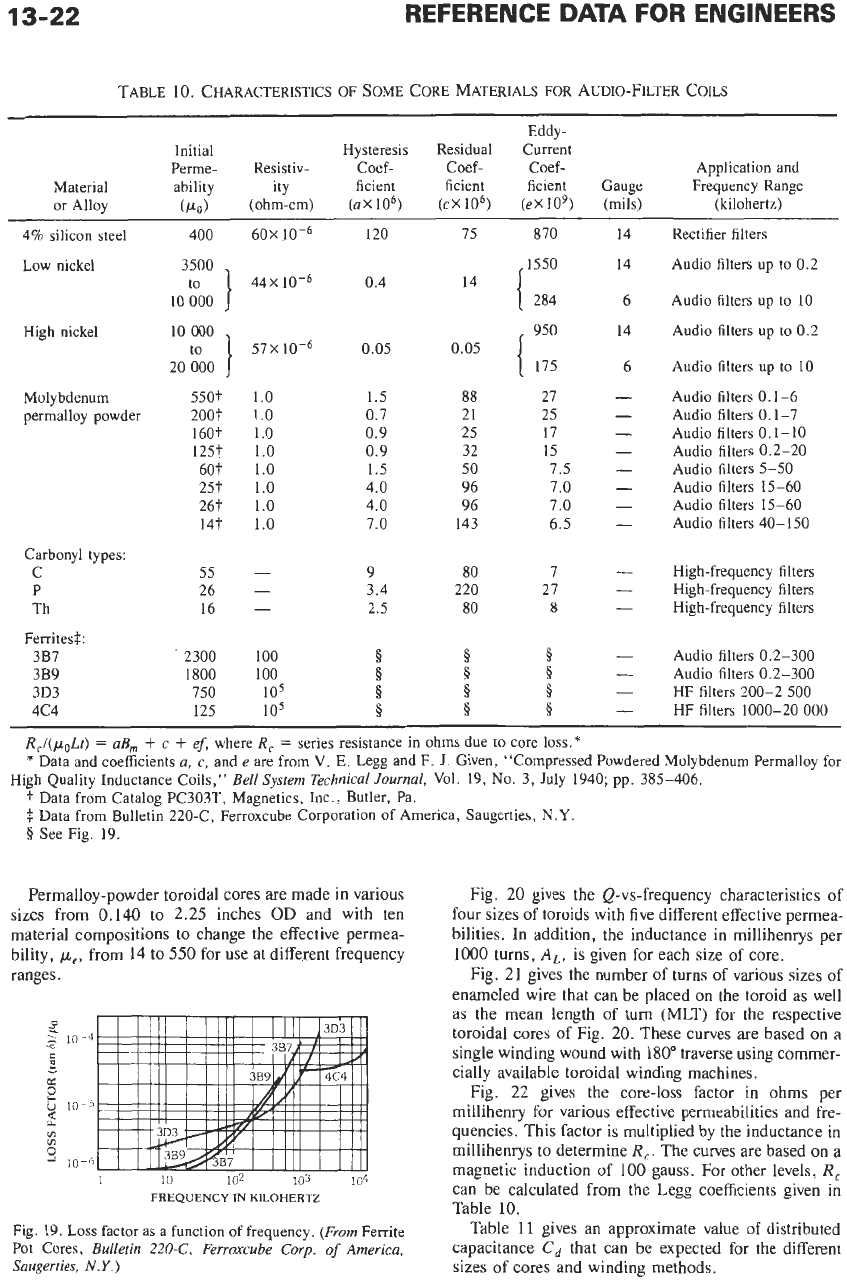
Permalloy-powder toroidal cores are made in various
sizes from
0.140
to 2.25 inches
OD
and with ten
material compositions to change the effective permea-
bility,
pe,
from
14
to
550
for use at different frequency
ranges.
i
2
10-4
2
3
c
-
K
t;
10-5
2
VI
1 10
102
103
104
FREQUENCY
IN
KILOHERTZ
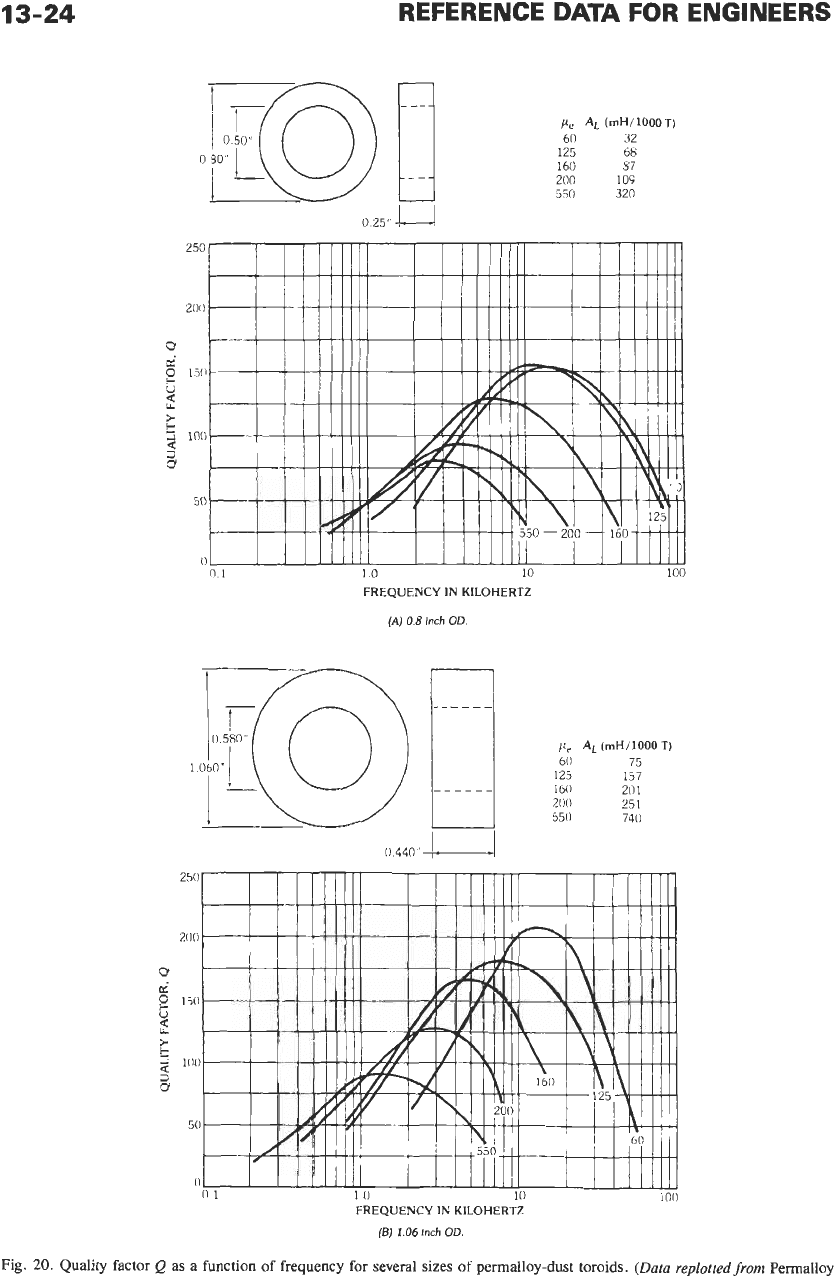
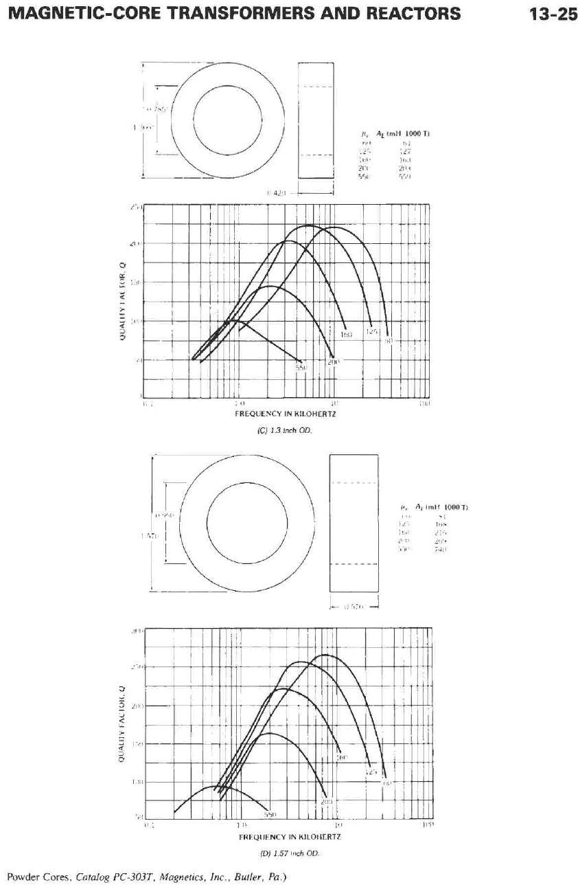
Fig. 20 gives the Q-vs-frequency characteristics of
four sizes of toroids with five different effective permea-
bilities. In addition, the inductance in millihenrys per
1000
turns,
A,,,
is given for each size
of
core.
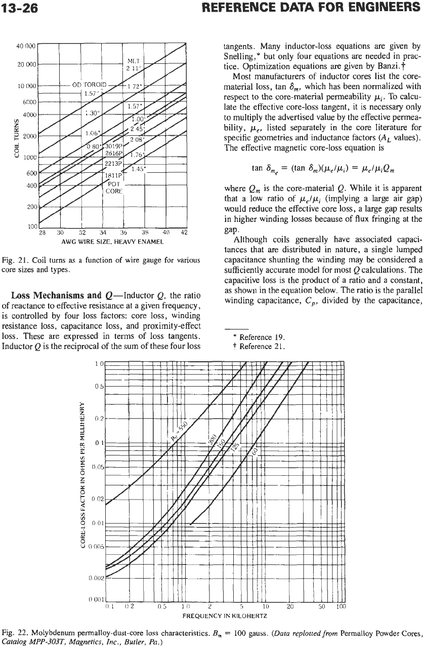
Fig.
21 gives the number
of
turns
of
various sizes
of
enameled wire that can be placed on the toroid as well
as
the
mean length of
turn
(MLT)
for the respective
toroidal cores of
Fig.
20. These curves are based on a
single winding wound with
180”
traverse using commer-
cially available toroidal winding machines.
Fig. 22 gives the core-loss factor
in
ohms per
millihenry for various effective pemeabilities and fre-
quencies. This factor is multiplied by the inductance in
millihenrys
to
determine
R,.
The
curves
are based on a
magnetic induction of
100
gauss.
For
other levels,
R,
can be calculated from the Legg coefficients given
in
Table 10.
Fig.
19.
Loss
factor as a function of frequency. (From Ferrite
Pot Cores, Bulletin
220-c,
Ferroxcube
Corp.
of
America,
Saugerties,
N.
Y.
)
Table
11
gives an approximate value
of
distributed
capacitance
Cd
that can be expected for the different
sizes
of
cores and winding methods.

MAGNETIC-CORE TRANSFORMERS AND REACTORS
13-23
When maximum temperature stability of inductance
is required, most manufacturers of permalloy toroidal
cores can provide various types of stabilized cores. The
stabilizations most used are listed in Table 12.
Since the distributed capacitance changes rapidly
with temperature, it should be kept to a minimum to
avoid changing the inductance.
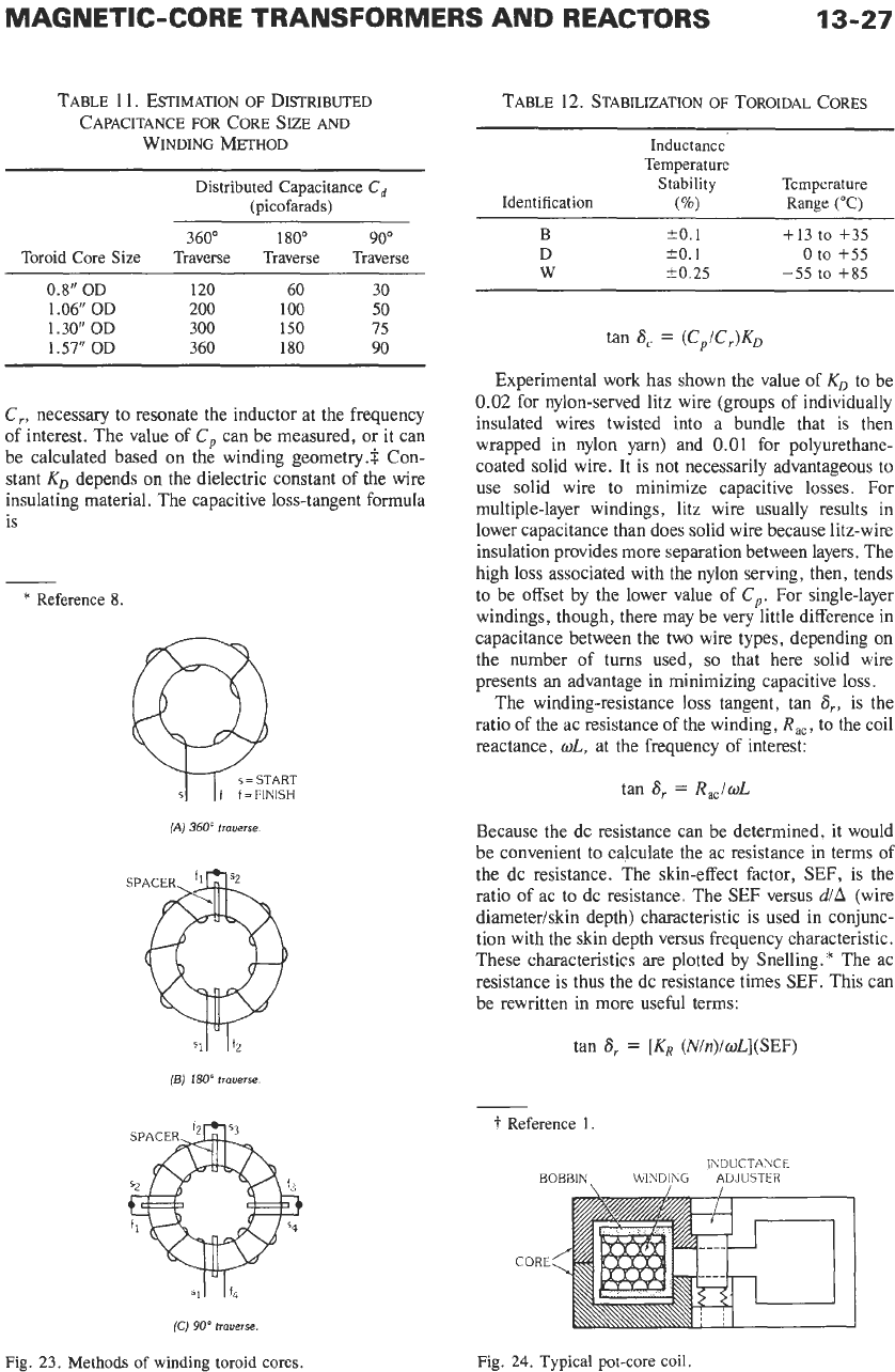
Fig. 23 illustrates the most common methods of
winding toroids. In Fig. 23A the toroid is rotated over a
360" arc for every layer of the winding (called 360"
traverse winding). In Fig. 23B, the toroid is rotated over
a 180" arc for each layer until half the coil is wound. The
other half of the winding is similarly wound. This is
called 180" traverse winding.
In
Fig. 23C the toroid is
rotated over only 90" until one quarter is wound. The
other three quarters are wound in the same manner.
This winding method is called 90" traverse or quadra-
ture winding.
Since most toroid cores are made with a tolerance of
28%
on
the
AL
(millihenrys/1000 turns), it is usually
necessary to adjust the inductance after winding. This
is
done by winding about
5%
more turns than calculated
on
the core and removing turns until the inductance
reaches the desired value. Coils for series-tuned meshes
should be adjusted to the resonance frequency of the
mesh with the tuning capacitor in series to eliminate the
effect of distributed capacitance. Coils for parallel
tuned meshes should be adjusted at low frequency in
such a way that the tuning capacitance is 1000 times the
distributed capacitance for
0.1%
accuracy.
Toroidal Core Design Example-It is desired to
design an inductor of 100 millihenrys for a series-tuned
mesh that resonates at
10
kilohertz. The Q must be
150
minimum and the size as small as possible.
(A)
Consulting the
Q
curves of Fig. 20B shows that a
1.06-inch
OD
toroid core with
p,
=
125 is the smallest
core that will meet the Q requirements. This has an
A,
value of 157 millihenrys per 1000 turns.
(B)
From Table 1 1,
Cd
=
200 picofarads. Calculate
L from Fig. 18:
L,
1
+
02LsCd
1
+
(2T10000)2
x
0.1
x
200
x
10-12
L=
100
- -
=
92.68 millihenrys
(C) Compute the number of turns required from
1/2
N
=
1000(Lrnillihenry~/~L)
=
1000(92.68/ 157p2
=
768 turns
(D)
Fig. 21 gives the maximum size of wire and
mean length of turn. Use
No.
30 heavy enameled wire
for 768 turns.
On
a 1.06-inch
OD
core the (MLT)
is
1.57 inches.
(E) Calculate R, from (MLT),
N,
and Table
5.
(MLT)
X
N
X
ohms/lOOO ft
12
000
R,
=
-
1.57
X
768
X
103.2
-
12
000
=
10.36 ohms
(F)
Calculate R, from R/L values of Fig. 22 for
p,
=
125 andf= 10 kilohertz. RIL
=
0.23 ohm/millihenry.
R,
=
(R/L)L
=
0.23
X
92.68
=
21.32 ohms.
(G)
Calculate Q per Fig. 16.
2~10
x
92.68
10.36
+
21.32
=
183.8
e=-----
WL
-
R,
+
R,
(H)
Calculate Q, per Fig. 18.
Q,
=
Q(1
-
w2LCd)
=
183.8[1
-
(2~10
OOO)*
X
0.09268
X
=
170.4
200
x
10-121
This should approximate the measured Q.
(I)
The coil is wound using 360" traverse winding,
and, since
no
special temperature stability is required, a
standard unstabilized core is used.
Precision Adjustable Inductors
Pot
Cores-Filter-class inductors are precision,
adjustable devices designed to provide high Q values at
a particular frequency. Although Q is often the greatest
concern, the temperature and time stability are usually
also important. While round pot-core structures are
very popular, other core shapes such as
RM,
X,
and
Q
are used to improve packing densities or magnetic
performance.
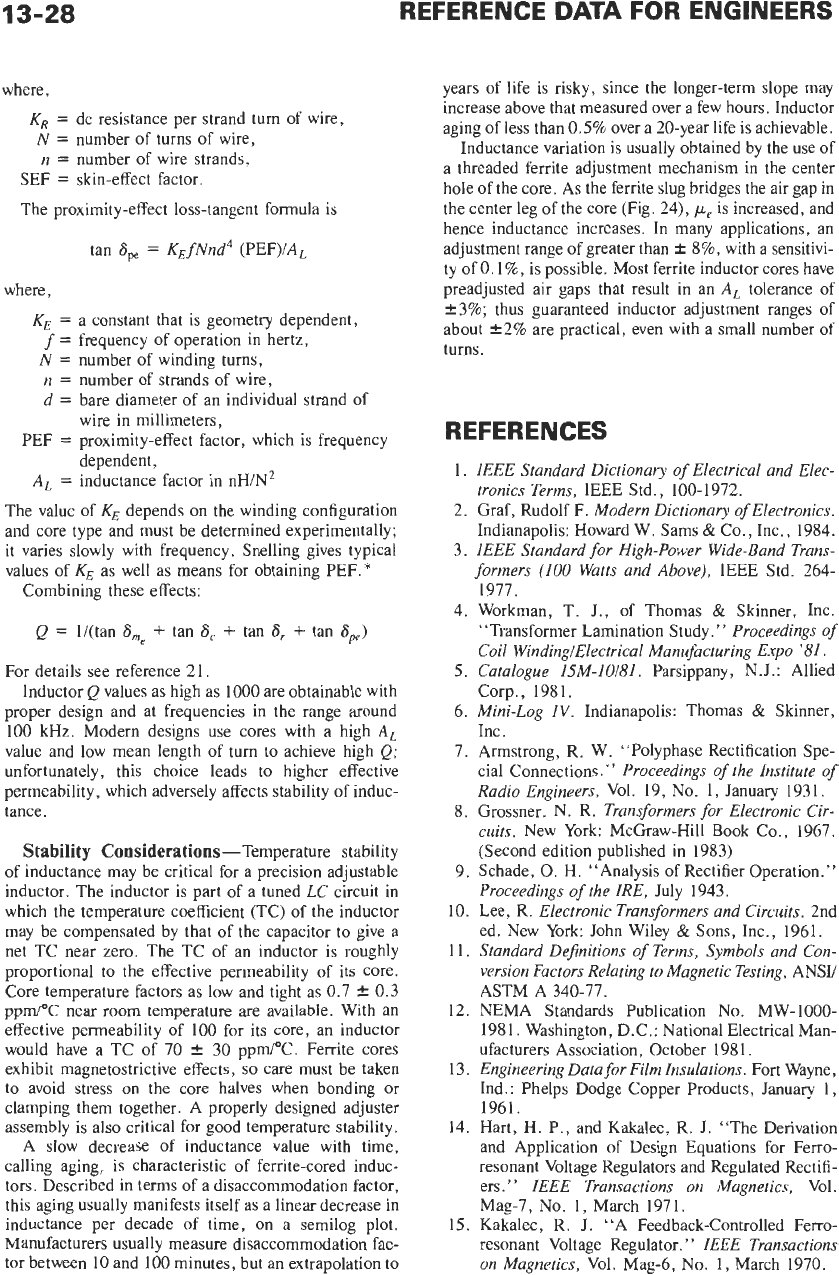
A cross-section of
a
typical pot-core inductor is
shown in Fig. 24. The two core halves are clamped or
cemented around a bobbin that contains the winding.
The ceramic ferrite cores are chosen specifically for
particular performance characteristics. A wide range of
permeabilities, loss characteristics, and stability perfor-
mance exists. The information is available
in
ferrite-
supplier catalogs.
The cores have a recessed center post
so
that when
they are mated,
an
air gap exists. Although the gap
reduces the effective permeability,
p,,
more important-
ly it reduces the core loss and temperature coefficient of
inductance. The gap is used to control the AL value (in
nanohenrys per turn squared), a most important induc-
tor design parameter. Inductors operating at low
fre-
quencies have relatively high values of
pe
and A,. AS
the operating frequency is increased, lower values of
these parameters usually are adequate.
13-24
REFERENCE
1
0
25"
DATA
FOR
p,
AL
(mH/1000T)
60
32
125
68
160
87
200
109
550
320
250
20(1
0
K
0
150
W
d
100
3
Y
50
0
01
10
10
100
FREQUENCY
IN
KILOHERTZ
(A)
0
8
inch
OD
pc
AL
(mH/1000T)
60
75
125
157
160
20
1
200
25
I
55(1
740
ENGINEERS
FREQUENCY IN KILOHERTZ
(E)
2.06
Inch
OD.
Fig.
20.
Quality factor
Q
as a function
of
frequency for several sizes of permalloy-dust toroids.
(Dura
replorredfrom
Permalloy
MAGNETIC-CORE TRANSFORMERS AND REACTORS
I!
4L!l"-
!,
:
i
(1
IO
FREQUENCY
IN
KILOHERTZ
[C)
1.3
Inch
OD.
13-25
Powder Cores,
Catalog PC-303T, Magnetics, Inc., Butler, Pa.)
13-26
REFERENCE
DATA
FOR ENGINEERS
AWG WIRE SIZE, HEAVY ENAMEL
tangents. Many inductor-loss equations are given by
Snelling,* but only four equations are needed in prac-
tice. Optimization equations are given by Banzi.?
Most manufacturers
of
inductor cores list the core-
material loss, tan
a,,
which has been normalized with
respect
to
the
core-material permeability
pj.
To calcu-
late the effective core-loss tangent, it is necessary only
to multiply the advertised value by the effective permea-
bility,
pe,
listed separately in the core literature for
specific geometries and inductance factors
(AL
values).
The effective magnetic core-loss equation is
tan
6me
=
(tan
Srn)(Pe/CLi)
=
Pe/PiQm
where Q, is the core-material
Q.
While it is apparent
that a low ratio of
pelpi
(implying a large air gap)
would reduce the effective core
loss,
a large gap results
in higher winding losses because of flux fringing at the
gap.
Although coils generally have associated capaci-
tances that are distributed in nature, a single lumped
Fig.
21.
Coil
turns
as
a
function
of
wire gauge for various
core sizes and types.
capacitance shunting the winding may be considerid a
sufficiently accurate model for most Q calculations. The
capacitive loss is the product
of
a ratio and a constant,
asshown in the equation below. The ratio is the parallel
winding capacitance,
C,,
divided by the capacitance,
Loss
Mechanisms
and
Q-lnductor
Q'
the
ratio
of reactance to effective resistance at a given frequency,
is controlled bv four loss factors: core loss. winding
-
resistance
loss,
capacitance loss, and proximity-effect
loss. These are expressed in terms
of
loss tangents.
Inductor Q is the reciprocal
of
the sum
of
these four
loss
-
*
Reference
19.
i.
Reference
21.
Fig.
22.
Molybdenum permalloy-dust-core
loss
characteristics.
B,
=
100
gauss.
(Data
replottedfrom
Permalloy Powder Cores,
Catalog
MPP-303T,
Magnetics,
Inc.,
Butler,
Pa)
MAGNETIC-CORE TRANSFORMERS
AND
REACTORS
13-27
TABLE
1 1. ESTIMATION
OF
DISTRIBUTED
CAPACITANCE
FOR
CORE SIZE
AND
WINDING METHOD
Distributed Capacitance
C,
(picofarads)
360"
180"
90"
Toroid Core Size Traverse Traverse Traverse
0.8"
OD 120 60
30
1.06" OD
200
100
50
1.30" OD 300
150
75
1.57"OD 360
180
90
C,,
necessary to resonate the inductor at the frequency
of interest. The value of
C,
can be measured, or it can
be calculated based on the winding geometry.$ Con-
stant
KD
depends on the dielectric constant of the wire
insulating material. The capacitive loss-tangent formula
is
-
*
Reference
8.
(A)
360°
trauerse
Sll
If2
(BJ
180"
traverse
(CJ
90"
trauerse.
Fig. 23. Methods
of
winding toroid cores.
TABLE 12. STABILIZATION
OF
TOROIDAL CORES
Inductance
Temperature
Stability
Temperature
Identification
(%)
Ranee
("0
B
20.1
+13
to
+35
D
20.1
0
to
+55
W
1-0.25
-55
to
+85
tan
8,
=
(C,/C,)K,
Experimental work has shown the value of
KO
to be
0.02 for nylon-served litz wire (groups of individually
insulated wires twisted into a bundle that is then
wrapped in nylon yarn) and
0.01
for polyurethane-
coated solid wire. It is not necessarily advantageous to
use solid wire to minimize capacitive losses. For
multiple-layer windings, litz wire usually results in
lower capacitance than does solid wire because litz-wire
insulation provides more separation between layers. The
high loss associated with the nylon serving, then, tends
to be offset by the lower value of
C,.
For single-layer
windings, though, there may be very little difference in
capacitance between the two wire types, depending on
the number of turns used,
so
that here solid wire
presents an advantage in minimizing capacitive loss.
The winding-resistance loss tangent, tan
a,,
is the
ratio of the ac resistance of the winding,
R,,,
to the coil
reactance,
oL,
at the frequency of interest:
tan
8,
=
R,,loL
Because the dc resistance can be determined, it would
be convenient to calculate the ac resistance in terms of
the dc resistance. The skin-effect factor,
SEF,
is the
ratio of ac to dc resistance. The SEF versus
d/A
(wire
diametedskin depth) characteristic is used in conjunc-
tion with the skin depth versus frequency characteristic.
These characteristics are plotted by Snelling.* The ac
resistance is thus the dc resistance times SEF. This can
be rewritten in more useful terms:
i
Reference
1.
IhDUCTAUCE
BOBBIN
WlYDIhG
ADJUSTER
CORE
tan
8,
=
[KR
(N/n)/wL](SEF)
Fig.
24.
Typical pot-core
coil
13-28
REFERENCE
DATA
FOR ENGINEERS
where,
KR
=
dc resistance per strand turn of wire,
N
=
number of turns of wire,
n
=
number of wire strands,
SEF
=
skin-effect factor.
The proximity-effect loss-tangent formula is
tan
6,,
=
KEfNnd4
(PEF)IA,
where,
KE
=
a constant that is geometry dependent,
f
=
frequency of operation in hertz,
N
=
number of winding turns,
n
=
number of strands of wire,
d
=
bare diameter of an individual strand of
PEF
=
proximity-effect factor, which is frequency
wire in millimeters,
dependent,
A,
=
inductance factor in nHIN2
The value of
KE
depends on the winding configuration
and core type and must be determined experimentally;
it varies slowly with frequency. Snelling gives typical
values of
KE
as well as means for obtaining PEF.*
Combining these effects:
Q
=
li(tan
6,e
+
tan
6,
+
tan
6,
+
tan
ape)
For details see reference 21.
Inductor
Q
values as high as 1000 are obtainable with
proper design and at frequencies in the range around
100 kHz. Modern designs use cores with a high
AL
value and low mean length of turn to achieve high
Q;
unfortunately, this choice leads to higher effective
permeability, which adversely affects stability of induc-
tance.
Stability Considerations-Temperature stability
of inductance may be critical for a precision adjustable
inductor. The inductor is part of a tuned
LC
circuit in
which the temperature coefficient (TC) of the inductor
may be compensated by that of the capacitor to give a
net TC near zero. The TC of an inductor is roughly
proportional to the effective permeability of its core.
Core temperature factors as low and tight as 0.7
f
0.3
ppm/OC near room temperature are available. With an
effective permeability of 100 for its core, an inductor
would have a TC
of
70
k
30 ppm/”C. Ferrite cores
exhibit magnetostrictive effects,
so
care must be taken
to avoid stress on the core halves when bonding or
clamping them together. A properly designed adjuster
assembly is also critical for good temperature stability.
A slow decrease
of
inductance value with time,
calling aging, is characteristic of ferrite-cored induc-
tors. Described in terms of a disaccommodation factor,
this aging usually manifests itself as a linear decrease in
inductance per decade of time,
on
a semilog plot.
Manufacturers usually measure disaccommodation fac-
tor between 10 and 100 minutes, but an extrapolation to
years of life is risky, since the longer-term slope may
increase above that measured over a few hours. Inductor
aging of less than
0.5%
over a 20-year life is achievable.
Inductance variation is usually obtained by the use of
a threaded ferrite adjustment mechanism in the center
hole of the core. As the ferrite slug bridges the air gap in
the center leg of the core (Fig. 24),
pc
is
increased, and
hence inductance increases. In many applications, an
adjustment range of greater than
i
8%,
with a sensitivi-
ty of
0.
I%,
is possible. Most ferrite inductor cores have
preadjusted air gaps that result in an
AL
tolerance
of
+3%;
thus guaranteed inductor adjustment ranges of
about t2% are practical, even with a small number of
turns.
REFERENCES
1.
2.
3.
4.
5.
6.
7.
8.
9.
10.
11.
12.
13.
14.
15.
IEEE Standard Dictionary
of
Electrical and Elec-
tronics Terms,
IEEE Std., 100-1972.
Graf, Rudolf F.
Modern Dictionary
of
Electronics.
Indianapolis: Howard W. Sams
&
Co., Inc., 1984.
IEEE Standard for High-Power Wide-Band Trans-
formers
(100
Watts and Above),
IEEE Std. 264-
1977.
Workman, T. J., of Thomas
&
Skinner, Inc.
“Transformer Lamination Study.
”
Proceedings
of
Coil WindingiElectrical Manufacturing Expo
’81.
Catalogue
I5M-I
Oi81.
Parsippany
,
N.
J
.
:
Allied
Corp., 1981.
Mini-Log
IV.
Indianapolis: Thomas
&
Skinner,
Inc
.
Armstrong, R. W. “Polyphase Rectification Spe-
cial Connections.
”
Proceedings of the Institute
of
Radio Engineers,
Vol. 19,
No.
1,
January 1931.
Grossner,
N.
R.
Transformers for Electronic Cir-
cuits.
New York: McGraw-Hill Book
Co.,
1967.
(Second edition published in 1983)
Schade,
0.
H.
“Analysis of Rectifier Operation.”
Proceedings of the IRE,
July 1943.
Lee, R.
Electronic Transformers and Circuits.
2nd
ed. New York: John Wiley
&
Sons, Inc., 1961.
Standard Dejinitions
of
Terms, Symbols and Con-
version Factors Relating to Magnetic Testing,
ANSU
ASTM A 340-77.
NEMA Standards Publication
No.
MW-1000-
1981. Washington, D.C.: National Electrical Man-
ufacturers Association, October 198
1.
Engineering Data for Film Insulations.
Fort Wayne,
Ind.: Phelps Dodge Copper Products, January
1,
1961.
Hart,
H.
P., and Kakalec,
R.
J. “The Derivation
and Application of Design Equations for Ferro-
resonant Voltage Regulators and Regulated Rectifi-
ers.”
IEEE Transactions
on
Magnetics,
Vol.
Mag-7,
No.
1,
March 1971.
Kakalec, R. J. “A Feedback-Controlled Ferro-
resonant Voltage Regulator.”
IEEE Transactions
on
Magnetics,
Vol. Mag-6, No. 1, March 1970.
MAGNETIC-CORE TRANSFORMERS AND REACTORS
13-29
16. Hart, H. P., and Kakalec, R.
J.
“ANew Feedback
Controlled Ferroresonant Regulator Employing a
Unique Magnetic Component.
’’
IEEE
Transac-
1971.
17. Pressman,
A.
I.
Switching and Linear Power
Sup-
ply, Power Converter Design.
Rochelle Park, New
Jersey: Hayden
Book
Co.,
Inc., 1977.
18. McLyman,
W.
T.
Transformer and Inductor De-
sign Handbook.
New York: Dekker Inc., 1978.
19. Snelling, E. C.
SoftFerrites.
The Chemical Rubber
20.
IEEE
Standard for Low-Power Pulse Transformers,
21. Banzi, Fred J., Jr., “Higher
Q
From Pot Core
Inductors.”
IEEE
Trans. Parts, Hybrids, and Pack-
aging,
Vol. PHP-13,
No.
4,
December 1977.
Co., 1969.
tions
on
Magnetics,
Vol. Mag-7,
No.
3, September
IEEE Std., 390-1975.
Power Electronics-
Rectifiers, Filters,
and
Power Supplies
Fred
G.
Turnbull
Revised
by
Ondrej
Pauk
Characteristics
of
Power Semiconductor Devices
14-3
Rectifiers
Schottky Rectifiers
Zener Diodes
Power Transistors
Insulated-Gate Bipolar Transistors
Field-Effect Transistors
Thyristors (Silicon Controlled Rectifiers)
MOS -Controlled Thyristors
Triacs
Transient-Voltage Suppressors
AC-DC Converter Circuits
14-12
Rectifier Circuits
Single-phase Voltage Multipliers
Phase-Controlled Thyristor Circuits
Linear Transistor Circuits
Switch-Mode Power Supplies
Basic Converters
Forward-Mode Converter Basics
Flyback
or
Boost-Mode Converters Basics
Power Semiconductors
in
Switch-Mode Power Supplies
Power MOSFETs
Bipolar Power Transistors
IGBTs
Rectifiers
Power Losses in Power Semiconductors
Turn-on Losses
14-1