Middleton W.M. (ed.) Reference Data for Engineers: Radio, Electronics, Computer and Communications
Подождите немного. Документ загружается.

+‘
denotes the phase for
s’(t),
the quantity to be
minimized is
loT
ai(t
-
u)
a,(t)
dt
cos(+
-
4’)
Since this should be small for all values of the phase
angles, it is necessary to minimize the magnitude of
for all values of
u.
The goal is to select the signature
sequences to accomplish this minimization (see refer-
ences 24 and 28).
Similar considerations arise for channels with specu-
lar multipath, narrow-band interference, hostile jam-
ming, and other forms of RFI. For complete discussions
of the problems of signature sequence selection see
references 24, 27, and 28. The problems of obtaining
phase and timing references for direct-sequence spread-
spectrum communication systems are discussed in ref-
erence 26. The performance of direct-sequence spread
spectrum with various forms of RFI is considered in
references 24, 25, and 36 through 38.
Frequency-Hop Spread-
Spectrum Communications
Signals with very large RF bandwidths can be gener-
ated by a method known as
frequency hopping
in which
the carrier frequency of a digital communication signal
is changed; or “hopped,” over a wide range of frequen-
cies. If the digital communication signal is
c(t)
=
A
a(t)
~0~[2.rrf,t
+
e(t)
+
41
the resulting
frequency-hopped
signal is
~(t)
=
A
a(t)
cos[2nf(t)t
+
e(t)
+
+I
The function
f(t),
which describes the carrier frequency
as a function of time, is called the (frequency)
hopping
pattern.
The hopping pattern is generated by applying a
random or pseudorandom sequence of inputs to a
frequency synthesizer. Typically, the available RF
bandwidth is partitioned into
q
nonoverlapping frequen-
cy intervals called
slots,
and the
q
different frequencies
generated by the frequency hopper are the center
frequencies for these slots.
A frequency-hop (FH) spread-spectrum signal with
hopping rate R, hops per second is a signal that has the
form
of
s(t)
above for which the frequency
f(t)
can
change every l/Rh seconds. The frequency is constant
on
intervals
of
length
Th
=
l/Rh. The parameter
Th
is
called the
frequency dwell time
or
hop interval.
In
contrast to direct-sequence spread-spectrum signals,
which occupy the full RF bandwidth at all times, FH
spread-spectrum signals occupy only a small fraction of
the RF bandwidth during a given hop interval.
Fast
FH
spread-spectrum systems
have hopping rates
that are larger than the data rate, and
so
the duration of a
data pulse is larger than the hop interval. Since the
transmission of a data pulse utilizes more than one of
the q frequency slots, frequency diversity is obtained
with fast FH spread-spectrum signaling.
Slow
FH
spread-spectrum systems
have hopping rates that are
smaller than the data rate, and thus the hop interval is
greater than the data symbol duration.
The total RF bandwidth of a slow FH spread-
spectrum signal is approximately q times the bandwidth
of the digital communication signal
c(t);
it is virtually
independent of the hopping rate. The total bandwidth of
a fast FH spread-spectrum signal depends
on
the
number of frequency slots and the hopping rate, but it
does not depend very much
on
the data rate.
The multiple-access capability of frequency-hop
spread spectrum is due to the fact that each signal
occupies only the fraction liq of the bandwidth during
each hop interval. Even for totally asynchronous opera-
tion of a large number of transmitters,* the hopping
patterns can be designed such that the probability of
interference between the signals from any two given
transmitters during a given hop interval is no more than
2/q. Since errors occur with high probability whenever
the signals interfere, some form of error-control coding
is necessary for typical multiple-access systems.
In
fact,
error-control coding is virtually a requirement for
frequency-hop spread-spectrum communication in the
presence of any form of partial-band or pulsed interfer-
ence. Convolutional codes and Reed-Solomon block
codes (see Chapter 25) appear to be the most suitable
error-correcting codes for use
in
frequency-hop spread-
spectrum communication systems.
REFERENCES
General References for Digital
Communications
1.
Benedetto,
S.,
Biglieri, E., and Castellani,
V.
Digital Transmission Theory.
Englewood Cliffs,
NJ: Prentice-Hall, 1987.
2. Blahut, R. E.
Digital Transmission
of
Information.
Reading,
MA:
Addison-Wesley, 1990.
3. Golomb,
S.
W., ed.
Digital Communications With
Space Applications.
Englewood Cliffs, NJ:
Prentice-Hall, Inc., 1964.
4. Helstrom, C. W.
Statisticul Theory
of
Signal
Detection.
2d ed. New York: Pergamon Press,
Inc., 1968.
5.
Lindsey, W.
C.,
and Simon,
M.
K.
Telecommuni-
cations Systems Engineering.
Englewood Cliffs,
NJ: Prentice-Hall, Inc., 1973.
~
*
Reference
29.
6.
7.
8.
9.
10.
11.
Proakis, J. G.
Digital Communications.
2nd ed.
New York: McGraw-Hill, 1989.
Pursley, M. B.
Introduction ,to Digital Communi-
cation Systems.
Reading, MA: Addison-Wesley,
scheduled for 1993.
Stein,
S.
Part
111
of
Communication Systems and
Techniques.
New York: McGraw-Hill Book Co.,
1966.
Van Trees, H.
L.
Detection, Estimation, and
Modulation Theory,
Part
I.
New York: John Wiley
&
Sons, Inc., 1968.
Weber, C. L.
Elements
of
Detection and Signal
Design.
New York: McGraw-Hill Book Co., 1968.
Wozencraft, J. M., and Jacobs,
I.
M.
Principles
of
Communication. Engineering.
New York: John
Wiley
&
Sons, Inc., 1965.
20. de Buda,
R.
“Coherent Demodulation of Fre-
quency-Shift Keying With Low Deviation Ratio.
”
IEEE Transactions
on
Communications,
Vol.
COM-20, June 1972, pp. 429-435.
21. Gronemeyer,
S.
A., and McBride, A. L. “MSK
and Offset QPSK Modulation.”
IEEE Transac-
tions
on
Communications,
Vol.
COM-24, August
22. Pasupathy,
S.
“Minimum Shift Keying: A Spec-
trally Efficient Modulation.”
IEEE Communica-
tions Magazine,
July 1979, pp. 14-22.
23. Ungerboeck,
G.
“Channel coding with multilevel/
phase signals.
’’
IEEE Transactions
on
Information
Theory,
Vol.
28,
January 1982, pp. 55-67.
1976, pp. 809-820.
12.
13.
14.
Spread
-
Spectrum
Communications
Noncoherent Communication
Over Nonselective Fading
Channels
24. Pursley, M.
B.
“Spread-Spectrum Multiple-
Access Communications.
’’
In
Multi-User Commu-
Turin, G. L. “Error Probabilities for Binary Sym-
metric Ideal Reception Through Nonselective Slow
Fading and Noise.”
Proceedings
of
the IRE,
Vol.
46, September 1958, pp. 1603-1619.
Lindsey, W. C. “Error Probabilities for Rician
Fading Multichannel Reception
of
Binary and
N-ary Signals.”
IEEE Transactions
on
Informa-
tion Theory,
October 1964, pp. 339-350 (re-
printed in reference 14).
Brayer,
K.,
ed.
Data Communications Via Fading
Channels.
New York: IEEE Press, 1975.
nication Systems.
G. Longo, ed. Vienna and New
York: Springer-Verlag, 1981, pp. 139-199.
25. Pickholtz, R. L., Schilling,
D.
L., and Milstein,
L. B. “Theory
of
Spread-Spectrum Communica-
tions-A Tutorial.
’’
IEEE Transactions
on
Com-
munications,
Vol. COM-30, May 1982, pp. 855-
884.
26. Holmes, J. K.
Coherent Spread Spectrum Systems.
New York: John Wiley
&
Sons, Inc., 1982.
27. MacWilliams, F. J., and Sloane,
N.
J. A.
“Pseudo-Random Sequences and Arrays.”
Pro-
ceedings
of
the IEEE,
Vol. 64, December 1976,
15.
16.
17.
18.
19.
pp. 1715-1729.
28. Sarwate, D.
V.,
and Pursley, M.
B.,
“Cross-
correlation Properties of Pseudorandom and Relat-
ed Sequences.”
Proceedings
of
the IEEE,
Vol. 68,
May 1980, pp. 593-619.
29. Geraniotis, E. A., and Purslev, M.
B.
“Error
’Bandwidth-Eff icient
Modulation (QPSK, OQPSK,
MSK, CPFSK, and Trellis-Coded
Modulation)
Amoroso, F. “The Bandwidth of Digital Data
Signals.
”
IEEE Communications Magazine,
No-
vember 1980, pp. 13-24.
Amoroso, F., and Kivett,
J.
A.
“Simplified
MSK
Signaling Technique.
”
IEEE Transactions
on
Communications,
Vol. COM-25, April 1977, pp.
Anderson, J. B., Aulin,
T.,
and Sundberg, C.-E.
Digital Phase Modulation.
New York: Plenum,
1986.
Biglieri, E., Divsalar, D., McLane,
P.
J.,
and
Simon,
M.
K.
Introduction
to
Trellis-Coded Mod-
ulation with Applications.
New York: Macfnillan,
1991.
Forney, G. D., Jr., Gallager, R. G., Lang, G. R.,
Longstaff, F.
M.,
and Qureshi,
S.
U. “Efficient
modulation for band-limited channels.
”
IEEE
Journal
on
Selected Areas
in
Communications,
Vol.
2,
September 1984, pp. 632-647.
433-441.
Probabilities for Slow-Frequenci-Hopped Spread-
Spectrum Multiple-Access Communications Over
Fading Channels.
”
IEEE Transactions
on
Commu-
nications,
Vol. COM-30, May 1982, pp. 996-
1 009.
30. Stark, W. E. “Coding for frequency-hopped
spread-spectrum communication with partial-band
interference,” Parts
I
and
11.
IEEE Transactions
on
Communications,
Vol.
33, October 1985, pp.
31. Pursley,
M.
B.
“Frequency-hop transmission for
satellite packet switching and terrestrial packet
radio networks.
”
IEEE Transactions
on
Informa-
tion Theory,
Vol. 32, September 1986, pp. 652-
667.
32. Pursley, M. B. “The role
of
spread spectrum in
packet radio networks.”
Proceedings
of
the IEEE,
Vol. 75, January 1987, pp. 116-134.
33. Simon, M. K., Omura,
J.
K.,
Scholtz, R.
A.,
and
1036-1057.
Levitt,
B.
K.
Spread Spectrum Communications,
Vol.
1-111.
Rockville, MD: Computer Science
Press, 1985.
34. Ziemer,
R.
E.,
and Peterson, R. L.
Digital Com-
munications and Spread Spectrum Systems.
New
York: Macmillan, 1985.
35.
Cooper, G.
R.,
and McGillem, C. D.
Modern
Communications and Spread Spectrum.
New York:
McGraw-Hill, 1986.
36. Special
Issue
on Spread-Spectrum Communica-
tions,
IEEE
Transactions
on
Communications,
Vol. COM-25, August 1977.
REFERENCE
DATA
FOR ENGINEERS
37. Special Issue
on
Mobile Spread-Spectrum Com-
munications,
IEEE
Transactions
on
Vehicular
Technology,
Vol: VT-30, February 1981.
38. Special
Issue
on Spread-Spectrum Communica-
tions,
IEEE
Transactions
on
Communications,
Vol. COM-30, May 1982.
39. “Spread Spectrum Communications
I.”
IEEE
Journal
on
Selected Areas in Communications,
Vol.
8,
No.
4,
May 1990.
40. “Spread Spectrum Communications
11.”
IEEE
Journal
on
Selected Areas in Communications,
Vol. 8,
No.
5,
June 1990.
25
Information
Theory
and Coding
Richard
E.
Blahut
Coding for Noiseless Channels
25-4
Capacity of Discrete Noiseless Channels
State Diagrams and Trellises
Source Compaction Codes
25-7
Source Models
The Entropy Function
Source Encoding
Fixed-Length Block Codes
Variable-Length Block Codes
Variable-Length Tree Codes
Universal Codes
Coding for Discrete Noisy Channels
Mutual Information
Channel Capacity
Error-Control Codes
Block Codes
Convolutional Codes
Continuous Channels and Sources
The Sampling Theorem
Differential Entropy
Entropy Power
Capacity
of
a Continuous Channel
25-1
I
25-1 7
The
Additive Gaussian Noise Channel
Waveform Channels
Bit Energy and Bit Error Rate
Signaling Without Bandwidth Constraints
Signaling With a Bandwidth Constraint
25-
1
25-2
REFERENCE
DATA
FOR ENGINEERS
Decision Theory and Estimation Theory
25-22
Hypothesis Testing
Estimation Theory
The Matched-Filter Estimator
Maximum Entropy and Minimum Discrimination
Spectral Estimation
Source Compression Codes 25-25
The Distortion-Rate Function
Multiterminal Information Networks 25-26
Two-way Channels
Broadcast Channels
Degraded Diversity Systems
Remote Compaction
of
Dependent Data
The Communication Games 25-27
The Jammer Saddle Point
Spectrum Spreading
Cry PtograPhY
Information theory is a discipline centered around a
common mathematical approach to the study
of
the
collection and manipulation of information. It studies
the theoretical basis
of
such activities as observation,
measurement, data compression, data storage, commu-
nication, estimation, decision making, and pattern
recognition. Many complex and expensive systems are
built for automating
or
expanding these operations.
Information theory attempts to guide the development
of such systems based on a study of the possibilities and
limitations inherent in mathematics and probability
theory.
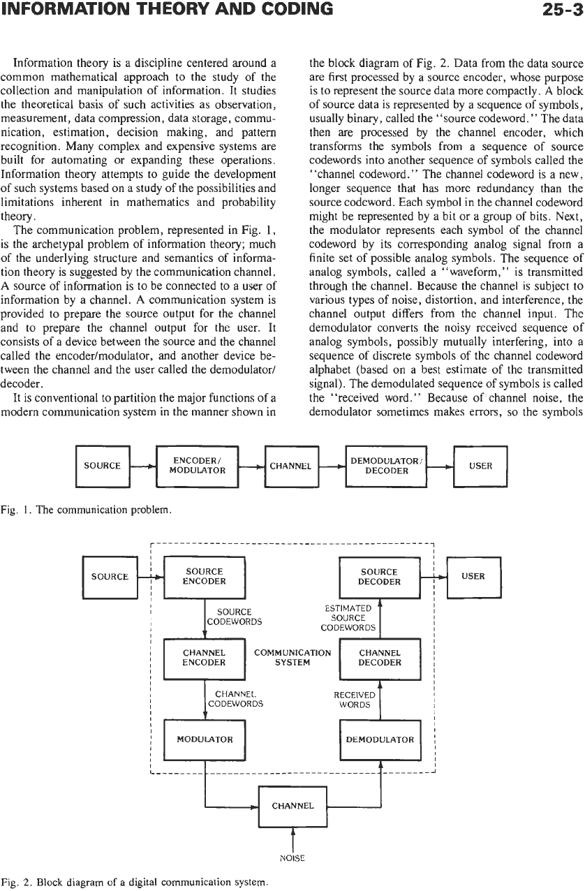
The communication problem, represented in Fig.
1,
is the archetypal problem of information theory; much
of the underlying structure and semantics
of
informa-
tion theory is suggested by the communication channel.
A
source
of
information is to be connected to a user of
information by a channel.
A
communication system is
provided to prepare the source output for the channel
and to prepare the channel output for the user. It
consists of a device between the source and the channel
called the encodedmodulator, and another device be-
tween the channel and the user called the demodulator/
decoder.
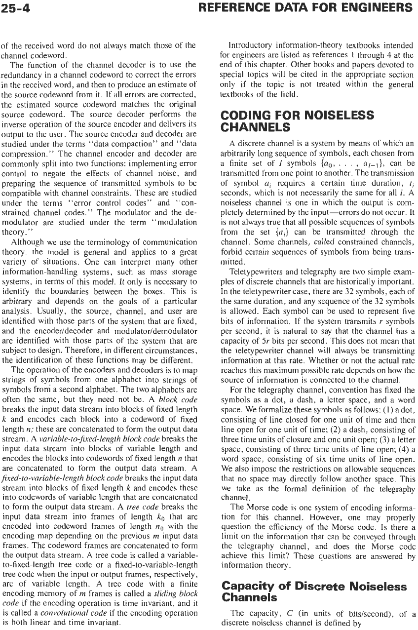
It is conventional to partition the major functions
of
a
modern communication system in the manner shown in
SOURCE
the block diagram
of
Fig.
2.
Data from the data source
are first processed by a source encoder, whose purpose
is to represent the source data more compactly.
A
block
of
source data is represented by a sequence of symbols,
usually binary, called the “source codeword.” The data
then are processed by the channel encoder, which
transforms the symbols from a sequence
of
source
codewords into another sequence of symbols called the
“channel codeword.” The channel codeword
is
a new,
longer sequence that has more redundancy than the
source codeword. Each symbol in the channel codeword
might be represented by a bit or a group
of
bits. Next,
the modulator represents each symbol of the channel
codeword by its corresponding analog signal from a
finite set of possible analog symbols. The sequence of
analog symbols, called a “waveform,” is transmitted
through the channel. Because the channel is subject to
various types of noise, distortion, and interference, the
channel output differs from the channel input. The
demodulator converts the noisy received sequence of
analog symbols, possibly mutually interfering, into a
sequence
of
discrete symbols
of
the channel codeword
alphabet (based on a best estimate of the transmitted
signal). The demodulated sequence
of
symbols is called
the “received word.
”
Because
of’
channel noise, the
demodulator sometimes makes errors,
so
the symbols
USER
DEMODULATOR1
DECODER
-
CHANNEL
L
ENCODER/
MODULATOR
-
--+
-1
I
I
SOURCE
+
I
I
Fig.
1.
The
communication problem
I
I I
I
USER
SOURCE SOURCE
DECODER
4
ENCODER
I
I
/
MODULATOR
I
,
I
Fig.
2.
Block diagram
of
a digital communication system.
I
I
DEMODULATOR
I
I
I
I
I
i
I
L-__-_-----------__----------------------------~
CHANNEL
25-4
REFERENCE DATA FOR ENGINEERS
of the received word do not always match those of the
channel codeword.
The function of the channel decoder is to use the
redundancy in a channel codeword
to
correct the errors
in the received word, and then
to
produce an estimate of
the source codeword from it. If all errors are corrected,
the estimated source codeword matches the original
source codeword. The source decoder performs the
inverse operation of the source encoder and delivers its
output
to
the user. The source encoder and decoder are
studied under the terms “data compaction” and “data
compression.
”
The channel encoder and decoder are
commonly split into two functions: implementing error
control to negate the effects of channel noise, and
preparing the sequence of transmitted symbols to be
compatible with channel constraints. These are studied
under the terms “error control codes” and “con-
strained channel codes.” The modulator and the de-
modulator are studied under the term ‘‘modulation
theory.
”
Although we use the terminology of communication
theory, the model is general and applies to a great
variety of situations. One can interpret many other
information-handling systems, such as mass storage
systems, in terms of this model. It only is necessary to
identify the boundaries between the boxes. This is
arbitrary and depends on the goals of a particular
analysis. Usually, the source, channel, and user are
identified with those parts of the system that are fixed,
and the encoder/decoder and modulator/demodulator
are identified with those parts of the system that are
subject to design. Therefore, in different circumstances,
the identification of these functions may be different.
The operation of the encoders and decoders is to map
strings of symbols from one alphabet into strings of
symbols from a second alphabet. The two alphabets are
often the same, but they need not be. A
block code
breaks the input data stream into blocks of fixed length
k
and encodes each block into a codeword of fixed
length
n;
these are concatenated to form the output data
stream. A
variable-to-fuced-length
block code
breaks the
input data stream into blocks of variable length and
encodes the blocks into codewords of fixed length
n
that
are concatenated
to
form the output data stream. A
fuced-to-variable-length
block code
breaks the input data
stream into blocks of fixed length
k
and encodes these
into codewords of variable length that are concatenated
to form the output data stream. A
tree code
breaks the
input data stream into frames of length
k,
that are
encoded into codeword frames of length
no
with the
encoding map depending
on
the previous
rn
input data
frames. The codeword frames are concatenated to form
the output data stream. A tree code is called a variable-
to-fixed-length tree code or a fixed-to-variable-length
tree code when the input or output frames, respectively,
are of variable length. A tree code with a finite
encoding memory
of
rn
frames is called a
sliding block
code
if the encoding operation is time invariant, and it
is called a
convolutional code
if the encoding operation
is
both linear and time invariant.
Introductory information-theory textbooks intended
for engineers are listed as references
1
through
4
at the
end
of
this chapter. Other books and papers devoted to
special topics will be cited
in
the appropriate section
only if the topic is not treated within the general
textbooks of the field.
CODING FOR NOISELESS
CHANNELS
A discrete channel is a system by means of which an
arbitrarily long sequence of symbols, each chosen from
a finite set of
I
symbols
{ao,
.
.
.
,
a!-,},
can be
transmitted from one point to another. The transmission
of symbol
ai
requires a certain time duration,
ti
seconds, which is not necessarily the same for all
i.
A
noiseless channel is one in which the output is com-
pletely determined by the input-errors do not occur. It
is not always true that all possible sequences of symbols
from the set
{ai}
can be transmitted through the
channel. Some channels, called constrained channels,
forbid certain sequences of symbols from being trans-
mitted.
Teletypewriters and telegraphy are two simple exam-
ples of discrete channels that are historically important.
In
the teletypewriter case, there are
32
symbols, each of
the same duration, and any sequence of the
32
symbols
is allowed. Each symbol can be used to represent five
bits of information. If the system transmits
r
symbols
per second, it is natural to say that the channel has a
capacity of
5r
bits per second. This does not mean that
the teletypewriter channel will always be transmitting
information at this rate. Whether or not the actual rate
reaches this maximum possible rate depends
on
how the
source of information is connected to the channel.
For the telegraphy channel, convention has fixed the
symbols as a dot, a dash, a letter space, and a word
space. We formalize these symbols as follows:
(1)
a dot,
consisting of line closed for one unit of time and then
line open for one unit
of
time;
(2)
a dash, consisting of
three time units of closure and one unit open;
(3)
a letter
space, consisting of three time units of line open;
(4)
a
word space, consisting of six time units of line open.
We also impose the restrictions on allowable sequences
that
no
space may directly follow another space. This
we take as the formal definition
of
the telegraphy
channel.
The Morse code is one system of encoding informa-
tion for this channel. However, one may properly
question the efficiency of the Morse code. Is there a
limit
on
the information that can be conveyed through
the telegraphy channel, and does the Morse code
achieve this limit? These questions are answered by
information theory.
Capacity
of
Discrete Noiseless
Channels
The capacity,
C
(in units of bits/second), of a
discrete noiseless channel is defined by
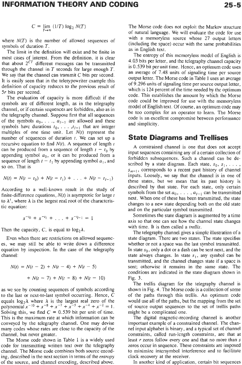
INFORMATION THEORY AND CODING
25-5
C
=
lim
(UT)
log2
N(T)
r-+x
where
N(T)
is the number of allowed sequences of
symbols of duration
T.
The limit in the definition will exist and be finite in
most cases of interest. From the definition, it is clear
that about
2CT
different messages can be transmitted
through the channel in
T
seconds for large enough
T.
We say that the channel can transmit
C
bits per second.
It is easily seen that in the teletypewriter example this
definition of capacity reduces to the previous result of
5r
bits per second.
The evaluation of capacity is more difficult if the
symbols are of different length, as in the telegraphy
channel, or if certain sequences are forbidden, also as in
the telegraphy channel. Suppose first that all sequences
of the symbols
ao,
. .
.,
ul-l
are allowed and these
symbols have durations
to,
.
.
.
,tl-l
that are integer
multiples of one time unit. Let
N(t)
represent the
number of sequences of duration
t.
We can set up a
recursive equation to find
N(t).
A sequence of length
L
can be produced from a sequence of length
t
-
to
by
appending symbol
ao,
or it can be produced from a
sequence of length
t
-
t
I
by appending symbol
a
I,
and
so
on. That is
N(t)
=
N(t
-
to)
+
N(t
-
ti)
+
. . .
+
N(t
-
ti-,)
According to a well-known result in the study of
finite-difference equations,
N(t)
is asymptotic for large
t
to
A',
where
A
is the largest real root of the characteris-
tic equation:
x-'0
+
,?-'I
+
.
.
.
+
x-"-l
=
1
Then the capacity,
C,
is equal to
log2A.
Even when there are restrictions on allowed sequenc-
es, we may still be able to write down a difference
equation by inspection. In the case of the telegraphy
channel:
N(t)
=
N(t
-
2)
+
N(t
-
4)
+
N(t
-
5)
+
N(t
-
7)
+
N(t
-
8)
+
N(t
-
10)
as we see by counting sequences of symbols according
to the last or next-to-last symbol occurring. Hence,
C
equals
log,A
where
A
is
the largest real zero
of
the
polynomial
x-'O
+
x-*
+
x-~
+
x-5
+
+
x-'
=
1.
Solving this, we find
C
=
0.539 bit per unit
of
time.
This is the maximum rate at which information can be
conveyed by the telegraphy channel. One may devise
many codes whose rates are close to the capacity of the
channel, but never greater.
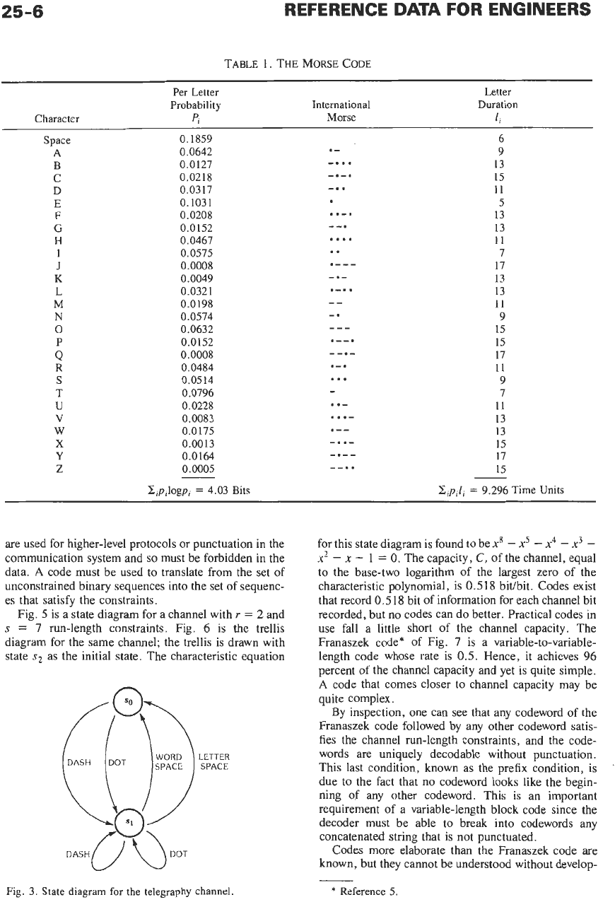
The Morse code shown in Table
1
is a widely used
code for transmitting written text over the telegraphy
channel. The Morse code combines both source encod-
ing, described in the next section in terms of the
entropy
of the source, and channel encoding, described above.
The Morse code does not exploit the Markov structure
of natural language. We will evaluate the code for use
with a memoryless source whose
27
output letters
(including the space) occur with the same probabilities
as in English text.
The entropy of this memoryless model of English is
4.03 bits per letter, and the telegraphy channel capacity
is 0.539 bit per unit time. Hence, an optimum code uses
an average of 7.48 units of signaling time per source
output letter. The Morse code in Table 1 uses an average
of 9.296 units of signaling time per source output letter,
which is 124 percent of the time needed by the optimum
code. This establishes the amount by which the Morse
code could be improved for use with the memoryless
model of English text. Of course, an optimum code may
be too complex for an operator to learn. The Morse
code is an excellent compromise between performance
and simplicity.
State
Diagrams
and
Trellises
A constrained channel is one that does not accept
input sequences containing any of a certain collection of
forbidden subsequences. Such a channel can be de-
scribed by a state diagram. Each state,
so,
sI,
,
.
.
,
sm-l,
corresponds to a recent past history of channel
inputs. Loosely, we say that the channel is in one of
these states, but we mean that its past history is
described by that state. For each state, only certain
symbols from the set
ao.
.
.
.
,
ul-l
can be transmitted
next. When one of these has been transmitted, the state
changes to a new state depending both on the old state
and on the particular symbol transmitted.
Sometimes the state diagram is augmented by a time
axis
so
that one can see how the channel state changes
with time. It is then called a
trellis.
The telegraphy channel gives a simple illustration of a
state diagram. There are two states. The state specifies
whether or not a space was the last symbol transmitted.
In state
so,
only a dot or a dash can be sent next, and the
state always changes. In state
sl,
any symbol can be
transmitted, and the channel changes state if a space is
sent; otherwise it remains in the same state. The
conditions are indicated in the state diagram shown in
Fig. 3.
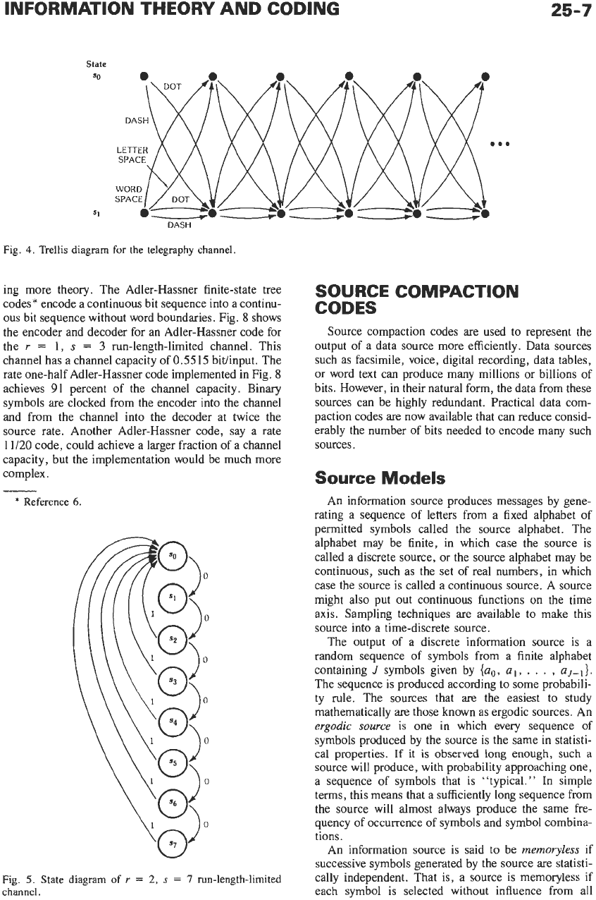
The trellis diagram for the telegraphy channel is
shown in Fig. 4. The Morse code is a collection of some
of
the paths through this trellis. An optimum code
would use all
of
the paths, but the mapping from the set
,of
source output sequences to the
set
of
trellis paths
might be a complicated one.
The digital magnetic-recording channel is another
important example of a constrained channel. The chan-
nel input alphabet is binary, and a typical set
of
channel
constraints, called run-length constraints, are that at
least
r
zeros follow every one and that no more than
s
zeros occur in sequence. These constraints are imposed
to minimize intersymbol interference and to facilitate
clock recovery at the receiver.
In another kind
of
application, certain bit sequences
25-6
TABLE 1. THE MORSE CODE
Character
Per Letter
Probability
pi
International
Morse
Letter
Duration
li
Space
0.1859 6
9
A
0.0642
13
€3
0.0127
15
C
0.0218
11
D
0.0317
E
0.1031 5
13
F
0.0208
13
G
0.0152
11
H
0.0467
7
I
0.0575
..
17
J
0.0008
13
K
0.0049
13
L
0.0321
11
M
0.0198
9
N
0.0574
15
0
0.0632
15
P
0.0152
17
0.0008
11
Q
R
0.0484
9
S
0.0514
...
T
0.0796 7
11
U
0.0228
13
V
0.0083
.
. .-
13
W
0.0175
15
X
0.0013
17
Y
0.0164
15
z
0.0005
x,p,l,
=
9.296
Time Units
.-
-.
. .
-.-.
-. .
..-.
--.
....
.---
-.-
.-.
.
--
-.
---
.--.
--.-
.-.
-
.
.-
.--
-..-
-.--
--..
-
-
x,p,logp,
=
4.03
Bits
are used for higher-level protocols or punctuation in the
communication system and
so
must be forbidden in the
data.
A
code must be used to translate from the set of
unconstrained binary sequences into the set of sequenc-
es that satisfy the constraints.
Fig.
5
is a state diagram for a channel with
Y
=
2
and
s
=
7
run-length constraints. Fig.
6
is the trellis
diagram for the same channel; the trellis is drawn with
state
s2
as the initial state. The characteristic equation
Fig.
3.
State diagram for the telegraphy channel.
for this state diagram is found to be
x8
-
x5
-
x4
-
x3
-
x2
-
x
-
1
=
0.
The capacity,
C,
of the channel, equal
to the base-two logarithm of the largest zero of the
characteristic polynomial, is
0.518
bivbit. Codes exist
that record
0.518
bit of information for each channel bit
recorded, but no codes can do better. Practical codes in
use fall a little short of the channel capacity. The
Franaszek code* of Fig.
7
is a variable-to-variable-
length code whose rate is
0.5.
Hence, it achieves
96
percent of the channel capacity and yet is quite simple.
A
code that comes closer to channel capacity may be
quite complex.
By inspection, one can see that any codeword
of
the
Franaszek code followed by any other codeword satis-
fies the channel run-length constraints, and the code-
words are uniquely decodable without punctuation.
This last condition, known as the prefix condition, is
due to the fact that no codeword looks like the begin-
ning of any other codeword. This is an important
requirement of a variable-length block code since the
decoder must be able to break into codewords any
concatenated string that is not punctuated.
Codes more elaborate than the Franaszek code are
known, but they cannot be understood without develop-
*
Reference
5.
25-7
State
SO
...
S1
DASH
Fig.
4.
Trellis
diagram for the telegraphy channel.
ing more theory. The Adler-Hassner finite-state tree
codes* encode a continuous bit sequence into a continu-
ous bit sequence without word boundaries. Fig.
8
shows
the encoder and decoder for an Adler-Hassner code for
the
r
=
1,
s
=
3
run-length-limited channel. This
channel has a channel capacity of
0.5515
bitlinput. The
rate one-half Adler-Hassner code implemented in Fig.
8
achieves
91
percent of the channel capacity. Binary
symbols are clocked from the encoder into the channel
and from the channel into the decoder at twice the
source rate. Another Adler-Hassner code, say
a
rate
11/20 code, could achieve a larger fraction of a channel
capacity, but the implementation would be much more
complex.
*
Reference
6.
Fig.
5.
State
diagram
of
r
=
2,
s
=
7
run-length-limited
channel.
SOURCE COMPACTION
CODES
Source compaction codes are used to represent the
output of a data source more efficiently. Data sources
such as facsimile, voice, digital recording, data tables,
or word text can produce many millions or billions of
bits. However, in their natural form, the data from these
sources can be highly redundant. Practical data com-
paction codes are now available that can reduce consid-
erably the number of bits needed to encode many such
sources.
Source
Models
An information source produces messages by gene-
rating a sequence of letters from a fixed alphabet of
permitted symbols called the source alphabet. The
alphabet may be finite, in which case the source is
called a discrete source, or the source alphabet may be
continuous, such as the set of real numbers, in which
case the source
is
called a continuous source. A source
might also put out continuous functions on the time
axis. Sampling techniques are available to make this
source into a time-discrete source.
The output of a discrete information source is a
random sequence of symbols from a finite alphabet
containing
J
symbols given by
{ao,
a,,
. .
.
,
aJ-
,}.
The sequence is produced according to some probabili-
ty rule. The sources that are the easiest to study
mathematically are those known as ergodic sources. An
ergodic source
is one in which every sequence of
symbols produced by the source is the same in statisti-
cal properties.
If
it
is
observed long enough, such a
source will produce, with probability approaching one,
a sequence of symbols that is “typical.” In simple
terms, this means that a sufficiently long sequence from
the source will almost always produce the same fre-
quency of occurrence
of
symbols and symbol combina-
tions.
An information source is said to be
memoryless
if
successive symbols generated by the source are statisti-
cally independent, That is, a source is memoryless if
each symbol is selected without influence from all