Moser A.P., Folkman S. Buried Pipe Design
Подождите немного. Документ загружается.

Steel and Ductile Iron Flexible Pipe Products 359
Because cracking and spalling of the mortar lining are the best indi-
cators of distress (performance limit) and because cracking and
spalling are caused primarily by change in radius of curvature of the
ring and by wall thickness t, it is necessary to relate these variables. A
theoretical equation for doing this is as follows:
e
(3.19)
where e maximum tangential strain in pipe ring
t wall thickness
D diameter
y/D vertical ring deflection
It is assumed that the ring remains essentially elliptical during deflec-
tion. As long as the D/t ratio is constant, according to Eq. (3.19), the flex-
ural strain is a function only of ring deflection y/D in an elliptical ring.
The flexural strain in Eq. (3.19) increases as wall thickness increases.
Actually, hydrostatic ring compression will affect strain also,
but usually
to a lesser extent. Therefore, the prediction of mortar cracking by ring
deflection is somewhat imprecise. Clearly it is more precise to predict
mortar cracking in terms of surface strain. However, as demonstrated in
the above equation, strain cannot be predicted unless the assumptions of
ellipticity are made; and under those assumptions, ring deflection is just
as good a fundamental variable as surface strain.
If the performance limit for design is spalling of the mortar lining, the
best parameters for design are D/t and either the single variable y/D
or the two variables and P, where is soil density and P is vertical soil
pressure ( and P determine y/D). Secondary criteria include type of
bell, bedding, etc. Precision does not justify the inclusion of secondary
criteria.
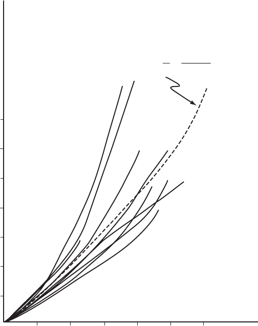
Figure 6.48 shows measured strain as a function of vertical ring
deflection for tests 4 through 12 on buried ductile iron pipe. Up to 3
percent deflection, the probable deviation is under 13 percent which
may not be too bad considering the great variability of soil placement.
It is also interesting to note that the plots fall randomly on both sides
of the theoretical equation, suggesting that greater precision requires
generally better soil control. No single variable is causing the devia-
tion. The assumption of elliptical configuration is as good as can be
achieved under typical techniques for soil placement.
Performance limit 2—bell cracking. Cracking of the bell, although a rare
phenomenon, was found to be basically a function of ring deflection
and the D/t ratio. Here again, design would be the same except for the
strength envelope which is based on a different performance limit.
3y/D
1 2y/D
t
D
360 Chapter Six
Performance limit 3—loss of compression in the gasket. Differential trans-
verse movement between the bell and spigot can cause high compression
of the gasket on one side of the joint with a consequent loss of compres-
sion on the other side. Similar loss of compression of the gasket can be
caused at opposite sides of the joint if either bell or spigot is not circular
(some ring deflection). Because the bell has a ring stiffness greater than
the spigot, when loaded, the bell tends to remain more nearly circular
and the spigot tends to deform out of round. The deflection of a spigot can
be calculated for a concentrated diametral load. However, soil loading is
different. If the ring is semiflexible (as is typical of ductile iron pipes),
then the deflection of the ring due to soil pressure is approximately ellip-
tical. If this assumption is adequate, then the loss of compression in the
gasket is a function of ring deflection y/D and the dimensions t and D.
Figure 6.48 Strain in pipe wall as a function of percent of vertical deflection.
()
Approximate Theoretical
Equation Assuming Elliptical
Configuration
Vertical Ring Deflection Δy/D (Percent)
7000
6000
5000
4000
3000
2000
1000
2
4
6
8
10 12
t
D
=
3 Δy/D
1–2Δy/D
7
8
9
5
10
6
11
12
4
e
Test Numbers
Tangential Strain Top Inside ε (Micro-Inch Per Inch)
Steel and Ductile Iron Flexible Pipe Products 361
As a result, the design method involves the same parameters y/D and
D/t as does cracking and spalling of the mortar lining. The only difference
would be the performance limit. Of course, a hard spot such as a rock out-
crop under the spigot would cause a nonelliptical deformation which
could result in loss of compression in the gasket. There is really no way
of predicting or controlling such an occurrence except by care and control
in the installation of the pipe and placement of the soil.
Instrumentation. On one 24-in and two 36-in tests, the primary objec-
tive was to determine the action of the spigot in relation to the bell
under external load. The secondary objective was to record pipe deflec-
tions for determining the structural performance of the pipe wall. These
three tests were instrumented much more extensively than the remain-
der of the tests. Two instruments especially designed and constructed
were used to trace the inside profile of the bell and spigot during load-
ing. One of these instruments was mounted at each joint. In order to
determine the offset condition at the throat, eight dial indicators were
mounted in tapped holes at 45 points around the circumference at the
position directly opposite the throat. Horizontal and vertical deflections
were taken with dial indicators at the midspan of the pipe. The bell and
spigot of each pipe was carefully measured with inside micrometers and
dial indicator thickness micrometers before and after the tests.
The primary objective of the remainder of the tests was to determine
a structural performance limit of the pipe wall with secondary obser-
vation of the action of the cement lining during loading. Instrumenta-
tion of these tests consisted of strain gages placed inside and outside
of the pipe wall at the midspan and vertical and horizontal deflection
readings at the bell and spigot of both joints and midspan. Joint deflec-
tions and pull-out were measured for all tests. Measurement of the
joints before and after the tests was also performed.
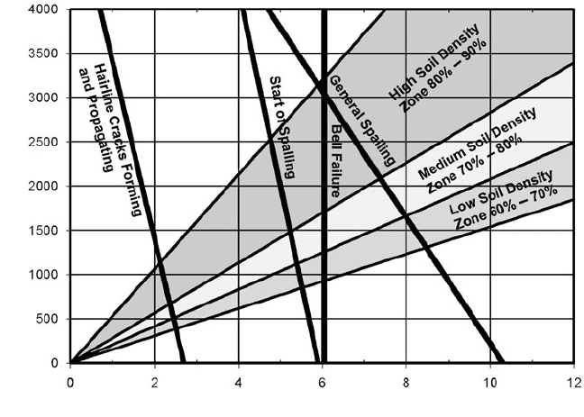
Test results. Figure 6.49 shows apparent ring compression stress ver-
sus percent vertical ring deflection at the midspan for the various
tests. The lower zone is for loose soil tests, the center zone for tests in
medium-dense soil, and the upper zone is for dense soil tests.
Figure 6.48 shows strain data for the various tests plotted as a func-
tion of percent of deflection. The dashed line in the figure is the plot of
the theoretical equation
It is interesting to note how closely this equation follows the data.
This equation can be derived by assuming the pipe deflects as an ellipse.
In other words, this shows that strain in the pipe wall can be determined
to a fair degree of accuracy from pipe geometry and deflection data.
However, it is obvious that other variables such as soil placement also
influence strain.
362 Chapter Six
Tests 4 through 10 were performed on pipes which were cement
lined. Tests 4 and 10 were in loose soil, and tests 5 through 9 were in
medium to dense soil. The cement lining performed similarly in both
loose soil and dense soil.
Prior to loading, each pipe was examined with a strong light, and all
existing cracks were marked. After each increment of load, the lining
was reexamined and any new cracks or old crack changes noted. All
pipe tested had cracked linings prior to installation. These cracks were
mainly confined to the spigot area. In some cases the lining was
unbonded in the spigot areas prior to installation.
As load is applied, the pipe deflects. Its vertical diameter decreases
significantly in the midspan of the pipe and usually to a lesser degree
at the joints. During this loading, the first significant change in the
cement lining is a crackling noise. In conjunction with this noise, small
hairline cracks appear in the tension areas and existing cracks tend to
lengthen. These cracks are generally parallel to the pipe axis and
extend only a short distance (in the range of 1 to 3 ft) down the pipe and
stop. As deflection proceeds, new cracks open parallel to the existing
cracks. These first cracks were approximately the same in appearance
as those cracks which occurred prior to installation. These first cracks
Percent Vertical Deflection
Apparent Ring Compression Stress PD/2A (lb/in
2
)
Figure 6.49 Ring compression stress versus ring deflection for buried ductile iron pipe.
Steel and Ductile Iron Flexible Pipe Products 363
should not be considered a performance limit of the cement lining since
the lining was not in danger of falling out or being washed out.
The second significant occurrence, which happened in every case,
was a spalling or flaking of the cement lining in the vicinity of the
bell. During this occurrence, pieces of cement lining fell out. The failure
was in the compression areas of the pipe bell (horizontal centerli ne).
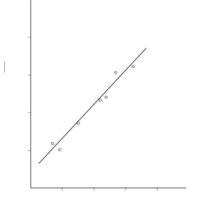
This spalling is defined as the performance li mit for the pipe tested.
Figure 6.50 shows the performance limit (critical ring compression
stress which will cause spalling at bell) as a function of average soil
density.
4000
3000
2000
1000
60 70
80
90
Soil Density r (Percent Standard AASHTO T-99)
Apparent Ring Compression Stress (lb/in
2
)
PD
2
A
10
11
12
9
5
7
6
Test Numbers
Figure 6.50 Performance limits for spalling at the bell.
364 Chapter Six
During the deflection immediately preceding and following the
spalling of the cement lining in the vicinity of the bell, an audible tear-
ing or unbonding occurred in four tests. Although present in the other
three tests, it appeared to have occurred very gradually, and the exter-
nal load at which it first started could not be determined. The load and
deflections at which this unbonding occurs is inconsistent and is seem-
ingly related to initial defects or unbonding which occurs during the
curing and/or handling of the cement-lined pipe prior to installation.
In four of the seven tests on 36-in cement-lined pipe, the perfor-
mance of the lining was climaxed by a general spalling in the com-
pression areas along one of the horizontal centerlines. The cement
lining of the remaining three test pipe was stress-relieved by cracks in
other areas, and general compression spalling did not occur.
As previously mentioned, there is a good possibility that the cement
lining in large-diameter pipes will be cracked due to handling or other
problems prior to installation. If these cracks remain small and unbond-
ing does not take place, the lining will continue to perform its intended
function—the prevention of tuberculation. A phenomenon called autoge-
nous healing takes place in Portland cement exposed to water. This phe-
nomenon in combination with swelling due to water absorption will tend
to close cracks. Therefore, it is more reasonable to define performance
limit as spalling of the lining or general unbonding, whichever occurs
first. Ring deflection, per se, ceases to be a performance limit.
During a test in 85 percent Proctor density soil, the performance limit
of the 36-in pipe was reached at a vertical soil pressure of 18,000 lbs/ft
2
when the bell on the full-length test piece suddenly cracked. Upon
visual examination, the crack was found to be completely through the
bell wall, extending approximately 15 in back from the face of the bell.
On two other tests similar failures occurred. These were installed in
soil of 75 and 67 percent average Proctor density, respectively. It
appears that a bell deflection of 6 percent is the lower limit for bell
failure. This corresponds to a deflection at the midspan of the barrel of
Spalling at Bell (Horizontal Centerline)
Percent deflection at bell
Test no. (100 y/barrel OD)
4 4.03
5 3.62
6 3.24
7 3.38
8 5.5
9 3.54
10 4.46
NOTE: Since the bell is much stiffer than
the midspan of the pipe, the bell deflection
usually occurs at a much lower rate.
Steel and Ductile Iron Flexible Pipe Products 365
approximately 10 percent. Photomicrographs made from specimens
taken from these bells all indicate the material to be a pearlite matrix
with nodular graphite. Tensile tests made from samples also indicated
a pearlitic structure.
Methods of design
The stress theory of design allows a structure to be designed analyti-
cally by setting the performance limit of the structure at a stress level
less than the yield point strength of a simple tensile specimen. Analyt-
ical equations for determining the stress level can be used for most
structures, thus eliminating costly experimental work in the design
stages. As long as the structure and the load are fairly simple and
dependable, a reliable structure can be designed by the so-called stress
theory of design.
It is well known, however, that some structures can fail before the
yield poi nt stress has been reached (elastic buckling) while other
structures continue to perform their functi on long after the yield
point of the outer fibers has been reached (plastic design of struc-
tures, see AISC Manual of Steel Construction). Therefore, the
design methods for many types of structures have been formulated
by the more reasonable approach of relating the variables or para-
meters governing the performance of the structure through experi-
mentation and then limiting the parameters to conservative values.
In the case of an internally pressurized pipe, the performance limit
can be the bursting of the pipe wall or leakage of the joint. If bursting
is the performance limit, the pertinent variables can be related using
the stress theory of design. The pertinent variables are
P
i
internal pressure, lb/in
2
D pipe diameter, in
A pipe wall cross-sectional area per unit length (in
2
/in)
thickness t
The allowable hoop tension stress is
t
where S
t
strength of pipe wall in tension, lb/in
2
, and N safety factor.
For design purposes,
t
is limited to values below the bursting
strength of the pipe by some safety factor N. If bursting strength is not
known, a conservative performance limit to choose is the yield point
(strength) of the pipe material.
S
t
N
P
i
D
2A
366 Chapter Six
In the case of a pipe externally loaded, the important variables are
1. EI/D
3
ring stiffness, lb/in
2
.Since E is a constant (24,000,000
lb/in
2
) for ductile iron, in this case, ring stiffness can be reduced to
D/A or D/t, where t is the wall thickness.
2. E¢ or a measure of soil stiffness, where E¢ soil stiffness and
density of soil (percent compaction).
3. P apparent vertical soil pressure (unit weight of soil, times height
of cover plus effect of surface loads at level of top of pipe).
4. y/D ring deflection, where y vertical decrease in diameter
and D diameter.
5. Performance limit.
Ring stiffness, soil density, and vertical soil pressure are indepen-
dent variables which are set by specification, etc., for each installation.
The performance limit and Δy/D are dependent variables depending
upon various combinations of ring stiffness, soil density, and vertical
soil pressure.
Ring stiffness and vertical soi l pressure can be combined in the con-
venient parameter PD/(2A). This parameter is very useful in the
stress theory of design for external hydrostatic pressure and is widely
used in the design of corrugated culvert pipe under external soil pres-
sure. Therefore, it is easily understood and simplifies design calcula-
tions. This form will be used to relate the independent variables. For
design, the value of PD/(2A) should be limited to a value well below
the performance limit; PD/(2A) has been related to soil density, per-
formance limit, and Δy/D through the tests. This relationship is shown
in Fig. 6.49.
Ring compression stress
c
where P calculated or apparent vertical soil pressure at level of top
of pipe
height of cover times unit weight of soil plus effect of sur-
face loads
D diameter of pipe
A wall cross-sectional area per unit length of pipe
wall thickness t for cylindrical pipe
S
c
compression strength of pipe wall
N safety factor
For design purposes,
c
must be limited to the ultimate compression
strength of the pipe wall and must be reduced by some factor of safety N.
S
c
N
PD
2A
Steel and Ductile Iron Flexible Pipe Products 367
This ultimate compression strength is simply the ring compression
stress PD/(2A) at performance limit as determined by actual tests. Two
examples of design follow.
Example 6.5 A 36-in ductile iron pipe is to be used to function with an
internal pressure of 200 lb/in
2
working pressure with a 100 lb/in
2
surge
pressure allowance and is to be buried under 30 ft of cover. What is the
required thickness for the internal pressure, and what should be the method
of installation, i.e., compaction of surrounding soil?
1. Calculate the required thickness.
t
where P
i
200 100 300 lb/in
2
D 38.30 in
N 2.5
S
t
42,000 lb/in
2
t 0.34 in
2. What is the soil density or percent of compaction required for this pipe to
withstand 30 ft of cover without spalling of the cement lining?
P 30 ft 120 lb/ft
3
3600 lb/ft
2
D 3.2 ft
A 0.34 in 12 in/ft 4.08 in
2
/ft
1412 lb/in
2
Entering Fig. 6.49 at PD/(2A)1412 lb/in
2
, we can see that if the density
of the soil is between 80 and 90 percent standard Proctor density, the deflec-
tion can be kept between 2.5 and 4.5 percent. A safety factor against cement-
lining spalling can be calculated as follows. At PD/(2A) 1412 lb/in
2
, the
cement lining would spall at about 5.2 percent. Therefore, the safety factor
is between 1.2 and 2.1. A 90 percent Proctor should be specified. A 90 percent
Proctor density can be obtained with a moderate amount of work on ordi-
nary soils by placing the soil in 1-ft lifts and passing over it with a rammer-
type compactor.
3600 lb/ft
2
(3.2 ft)
2 (4.08 in
2
/ft)
PD
2A
38.30 in
12 in/ft
300 (38.30) (2.5)
2 (42,000)
P
i
DN
2S
t
P
i
D
2t (1 in)
P
i
D
2A
S
t
N
368 Chapter Six
Example 6.6
A 36-in ductile iron pipe is to be designed for an internal pres-
sure of 200 lb/in
2
working pressure and 100 lb/in
2
surge pressure. It is to be
installed under 5 ft of cover under a roadway. Calculate the required thick-
ness for internal pressure, and recommend an installation procedure.
1. This is identical to Example 6.5. The required thickness is 0.34 in.
2.
P 5 ft 120 lb/ft
3
(live load)
600 340 940 lb/ft
2
369 lb/in
2
See Fig. 6.49.
If it is installed in loose soil (60 to 70 percent standard Proctor density),
the deflection is 1.8 to 2.5 percent. Therefore, the safety factor against cement-
lining spalling is about 2.3 to 3.1.
Note: Tamping is not required in this installation unless it is required to
protect the roadway pavement from damage.
Prequalification Testing of Pipes Used in
Underground Heating Distribution Systems
Introduction
For large institutions with multiple buildings, often there is a central
heating plant. The pipe used to carry the hot fluid to the buildings and
to return the condensate to the plant are insulated and are frequently
actually two concentric pipes (a casing pipe and a carrier pipe) with
insulation in the annulus between them. Such pipe must be tested to
demonstrate that the pipe system meets the criteria specified by the
Federal Agency Pre-Qualification Procedures for Underground Heat
Distribution Systems. The testing program is carried out in accordance
with a set test protocol. Test equipment to meet the protocol was
designed and constructed by the Buried Structures Laboratory at
Utah State University.
The test apparatus is described in the test protocol; however, pho-
tographs and diagrams are included here to give the reader some
visual perception of the actual test setup. Sample results of some tests
are also given. See Figs. 6.51 to 6.66.
Test protocol
System classification.
The thermal pipe and the condensate pipe must
be described and qualified for use in the specific site conditions such
as follows:
940 lb/ft
2
(32 ft)
2 (4.08 in
2
/ft)
PD
2A