Moser A.P., Folkman S. Buried Pipe Design
Подождите немного. Документ загружается.

Use Spangler’s equation.
H 60 ft D 48 in
Let
␥ 120 lb/ft
3
E 30 10
6
lb/in
2
E¢ 1000 lb/in (from Table 3.4)
Solve for EI/r
3
.
0.061 E¢
0.061(1000)
100 61 39
or
I
0.018 in
4
/in
0.22 in
4
/ft
From Table 6.4, the uncoated thickness should be 0.1345 in.
Now assume the yield stress
y
for the steel is 33,000 lb/in
2
. What wall
area is required for ring compression design with a safety factor of 2?
Design compression stress
Vertical soil pressure P
v
(120)(60) 7200 lb/ft
2
or
P
v
50 lb/in
2
f
c
; f
c
16,500 lb/in
2
y
2
PD
2A/L
PDL
2A
7200
144
39 (24)
3
30 10
6
39r
3
E
(0.1)(120)(60)(1/144)
0.05
0.1 ␥H
y/D
EI
r
3
0.1 ␥H
EI/r
3
0.061E¢
y
D
Steel and Ductile Iron Flexible Pipe Products 329

Solve for A/L.
0.073 in
2
/in
(0.073 in
2
/in) (12 in/ft) 0.88 in
2
/ft
From Table 6.4, the uncoated thickness is 0.0598 in. Thus, the deflection
design controls, and the thickness found in the beginning of the example is
the required thickness.
Steel pressure pipes are used in many varied and diverse applica-
tions in industrial, agricultural, and municipal markets. The discus-
sion here will be limited to steel pipe used primarily in the municipal
water market (see Table 6.5). However, principles used are applicable
to all steel pressure pipes.
AWWA M11, Steel Pipe—A Guide for Design
and Installation
This manual gives procedures for determining the required thickness for
steel pressure pipe. The internal pressure used in design should be that to
which the pipe may be subjected during its lifetime. The thickness selected
should be that which satisfies the most severe requirement. The minimum
thickness of a cylinder should be selected to limit the circumferential ten-
sion stress to a certain level. The maximum pressure in the pipe must be
used in the design calculations. Surge or water hammer pressures and
pressures created by the pumping operations must also be considered.
(50)(48)
2(16,500)
PD
2f
c
A
L
330 Chapter Six
TABLE 6.5 Selected Standards for Steel Pressure Pipes in Water Service
AWWA C200 Steel water pipe 6 in and larger
AWWA C203 Coal-tar protective coatings and linings for steel water pipelines—
enamel and tape applied hot
AWWA C205 Cement-mortar protective lining and coating for steel water pipe—
4 in and larger—shop-applied
AWWA C206 Field welding of steel water pipe
AWWA C207 Steel pipe flanges for waterworks service—sizes 4 through 144 in
(100 mm through 3600 mm)
AWWA C208 Dimensions for fabricated steel water pipe fittings
AWWA C209 Cold-applied tape coatings for special sections, connections, and
fittings for steel water pipelines
AWWA C210 Coal-tar epoxy coating system for the interior and exterior of steel
water pipe
AWWA C213 Fusion-bonded epoxy coating for the interior and exterior of steel
w
ater pipelines
AWWA C214 Tape coating systems for the exterior of steel water pipelines
AWWA C602 Cement-mortar lining of water pipelines in place—4 in (100 mm)
and larger
AWWA M11 Steel pipe design and installation

With pressure determined, the wall thickness is found by using
Eq. (4.2):
t
where t minimum specified wall thickness, in
P
i
internal pressure, lb/in
2
D outside diameter of pipe steel cylinder (not including
coatings), in
max
allowable stress, lb/in
2
For steel pipe, a design stress equal to 50 percent of the specified
minimum yield strength is often accepted for steel water pipe. This
design (working) stress is determined with relation to the steel’s yield
strength rather than its ultimate strength. For some applications, other
safety factors may apply. For example, the Bureau of Reclamation in its
design criteria for penstocks have adopted a safety factor of 3 based on
ultimate tensile strength or a safety factor 1.33 based on the minimum
yield strength.
Table 6.6 is reprinted from AWWA M11. It lists grades of steel ref-
erenced in AWWA C200, Standard for Steel Water Pipe 6 Inches and
P
i
D
2
max
Steel and Ductile Iron Flexible Pipe Products 331
TABLE 6.6 Grades of Steel Used in AWWA C200
Design stress Minimum Minimum ultimate
Specifications for 50% of yield point, yield point, tensile strength,
fabricated pipe lb/in
2
lb/in
2
lb/in
2
ASTM A 36 18,000 36,000 58,000
ASTM A 283 GR C 15,000 30,000 55,000
GR D 16,500 33,000 60,000
ASTM A 570 GR 30 15,000 30,000 49,000
GR 33 16,500 33,000 52,000
GR 36 18,000 36,000 53,000
GR 40 20,000 40,000 55,000
GR 45 22,500 45,000 60,000
GR 50 25,000 50,000 65,000
ASTM A 572 GR 42 21,000 42,000 60,000
GR 50 25,000 50,000 65,000
GR 60 30,000 60,000 75,000
Design stress Minimum Minimum ultimate
Specifications for 50% of yield point, yield point, tensile strength,
manufactured pipe lb/in
2
lb/in
2
lb/in
2
ASTM A 53,
A 135,
and A 139 GR A 15,000 30,000 48,000
GR B 17,500 35,000 60,000
ASTM A 139 GR C 21,000 42,000 60,000
GR D 23,000 46,000 60,000
GR E 26,000 52,000 66,000
Larger, and gives design stresses to be used as a basis for working
pressure. Also given are the yield stresses and the ultimate stresses for
the various grades of steel.
The designer can easily calculate working pressure, via Eq. (4.2),
corresponding to 50 percent of the specified minimum yield strength
for several types of steel commonly used. A required thickness may not
be available from a manufacturer. It is, therefore, recommended that
the pipe manufacturers be consulted before final selection of diameter
and wall thicknesses.
For transient pressures, the hoop stress may be allowed to rise,
within limits, above 50 percent of yield for transient loads. When
ultimate tensile strength is considered, a safety factor well over 2 is
realized. The stress of transitory surge pressures together with sta-
tic pressure may be taken at 75 percent of the yield point stress, but
should not exceed the mill test pressure. The designer should, how-
ever, never overlook the effect of water hammer or surge pressures
in design.
Internal pressure, external pressure, special physical loading, type
of lining and coating, and other practical requirements govern wall
thickness. Good practice with regard to internal pressure is to use a
working tensile stress of 50 percent of the yield point stress under the
influence of maximum design pressure. Select linings, coatings, and
cathodic protection, as necessary, to provide the required level of corrosion
protection.
The wall thickness selected must resist external loadings imposed
on the pipe. Such loadings may take the form of outside pressure,
either atmospheric or hydrostatic, both of which are uniform and act
radially as collapsing forces. Buried pipe must be designed to resist
earth pressure in trench or fill condition. These considerations are dis-
cussed in Chaps. 2 and 3.
For external pressure or internal vacuum, buckling should be con-
sidered. The following formula from Chap. 3 applies:
P
cr
3
(3.14)
where R radius to neutral axis of shell (for thin pipes, difference
between inside diameter, outside diameter, and neutral-
axis diameter is negligible), in
t wall thickness, in
P
cr
collapsing pressure, lb/in
2
E modulus of elasticity (30,000,000 for steel)
Poisson’s ratio (usually taken as 0.30 for steel)
t
R
E
4(1
2
)
332 Chapter Six
Substituting the above values of E and gives
P
c
528 10
6
3
(6.3)
For convenience to the reader, the more exact approach to buckling
is repeated here from Chap. 3 as follows:
q
a
32 RwB¢E¢
1/2
where q
a
allowable buckling pressure, lb/in
2
FS design factor
2.5 for (h/D) 2
3.0 for (h/D) 2
h height of ground surface above top of pipe, in
D diameter of pipe, in
R
w
water buoyancy factor
1 0.33(h
w
/h)0 h
w
h
h
w
height of water surface above top of pipe, in
B¢ empirical coefficient of elastic support (dimensionless)
Coefficient B¢ was given by Luscher in 1966. The equation is as follows:
B¢
The B¢ has some dependence on Poisson’s ratio for the soil. However,
this effect is small, as is shown in Fig. 3.22. The above equation sim-
plifies when the value for Poisson’s ratio is taken as
1
2
.This equation
is conservative and should be used for the calculation of B¢.
B¢
Minimum plate or sheet thicknesses for handling are based on two
formulas adopted by many specifying agencies:
t pipe sizes up to 54-in ID (6.4)
t pipe sizes greater than 54-in ID (6.5)
In no case shall the shell thickness be less than 14 gage (0.0747 in).
D 20
400
D
288
4(h
2
Dh)
1.5(2h D)
2
4 (h
2
Dh)
(1 )[(2h D)
2
D
2
(1 2)]
EI
D
3
1
FS
t
R
Steel and Ductile Iron Flexible Pipe Products 333
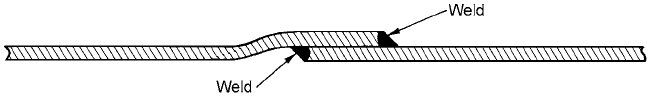
Example 6.3—108-in transmission A 108-in-diameter water transmission
line is to be installed. Steel has been selected as the piping material. The
joint is to be a bell-and-spigot type joint welded both inside and out as
shown:
334 Chapter Six
The wall thickness is to be 0.5 in. Because of the large diameter, the pipe
will be very flexible and will be braced with internal bracing (stills) when
manufactured. These stills will remain in the pipe sections until the pipes
have been installed and pipe zone soil has been placed and compacted to
the specified density. The stills wi ll be removed after backfilling is com-
plete. The pipeline will then be lined with a Portland cement type mortar
before the line is placed in service.
Design parameters:
Wall thickness 0.5 in
Yield stress 36,000 lb/in
2
Ultimate strength 60,000 lb/in
2
Modulus 29 10
6
lb/in
2
Poisson’s ratio 0.3
Thermal coefficient of expansion 6.5 10
6
(1/°F)
Ductile-brittle transition temperature 70°F
Surge pressure allowance 40 lb/in
2
Cover depth 6 ft
Pipe zone soil Crushed stone
Pipe zone density 90 percent standard Proctor
Water temperature 34°F
Evaluate the proposed steel pipe for this application. Are there any spe-
cial precautions which should be taken or special construction methods
which should be followed?
1. Check pipe stiffness PS and evaluate possible ring deflection.
PS 6.7
12.85 lb/in
2
This pipe is quite flexible. However, the pipe is going to be held in the
undeflected state until pipe zone soil is compacted and the overburden is
placed. The resulting deflection after the stills are removed will be quite low.
6.7 (29 10
6
) (0.5)
3
(12) (54)
3
EI
r
3
F
y
2. Check the pressure design. First, find the hoop stress for design pres-
sure plus surge.
h
17,280 lb/in
2
Second, find the hoop stress for design pressure only.
h
12,960 lb/in
2
The yield stress is 36,000 lb/in
2
. The safety factor is greater than 2; there-
fore, pressure design is all right.
3. Consider longitudinal stresses. AWWA C206 indicates that tempera-
ture considerations should be made in design. AWWA C206 and AWWA M11
suggest the use of either closure welds or expansion joints to alleviate
stresses due to temperature change.
Longitudinal stresses will also be produced by the Poisson effect. Tem-
perature stresses and Poisson stresses, along with bending stresses due to
nonparallel loading in the bell-spigot connection, may be large enough to
cause failure.
Assume the pipe is placed and tack-welded during the day. It is July and
August, and the pipe temperature during tack welding is between 80 and
130°F. The tack welds hold firm, and the welding process is completed by a
welding crew who are following behind the pipe-la
y
ing crew. No closure
welds or expansion joints are being used. After the line is completed, it is put
in service with water at 120 lb/in
2
and 34°F. (See Chap. 4, the steel pipe lon-
gitudinal stresses section.)
First, find the longitudinal stress due to the Poisson effect.
p
h
but
h
12,960 lb/in
2
p
(0.3)(12,960) 3888 lb/in
2
Second, find the longitudinal stress due to temperature change.
T
E (T)
(29 10
6
)(6.5 10
6
)(T)
(188.5)(T)
Assume T 70°F. Then
T
13,195 lb/in
2
Third, what is the total longitudinal stress?
L
(Poisson) (temperature)
3888 13,195 17,083 lb/in
2
(120) (108)
2 (0.5)
PD
2t
(120 40) (108)
2 (0.5)
PD
2t
Steel and Ductile Iron Flexible Pipe Products 335
Fourth, the nonparallel loading in the bell and spigot will produce a bend-
ing moment and will effectively magnify the stress found above. What is
that magnification factor?
Bending stress
B
where M moment
L
At
L
(bt)(t)
t thickness
A area bt
C
I
Therefore,
B
6
L
Then, the bending stress is 6 times the longitudinal stress. However, the
maximum stress is the sum of the bending stress and the longitudinal stress.
max
B
L
7
L
The magnification factor is 7. Therefore,
max
(7)(17,083) 119,581 lb/in
2
.
The pipe will fail before this stress is reached. In fact, it did. This pipeline
was actually designed and constructed as described in this example. The
designer failed to consider longitudinal stresses and did not allow for clo-
sure or expansion joints. There were three separate failures caused by lon-
gitudinal stresses. Each time a repair was made, the line was returned to
service. After the third failure, a general repair was ordered. Every other
joint was cut to relieve the built-in stresses. As the joints were cut, there
were snap-back openings of as much as 1 in. The temperature of the pipe
during the repair was 55F, w hich
i
s 21 higher than the service tempera-
ture, so there will still be some stress at 34F. Had the steel been more duc-
tile, it might have been able to relieve itself by simply stretching. For the
steel selected, the ductile-brittle transition temperature was 70F. There-
fore, the steel behaved in a brittle manner and failed.
Ductile Iron Pipe
Ductile iron pipe has essentially replaced gray cast iron pipe. Ductile
iron (DI) is, as its name implies, more ductile than gray cast iron, but still
retains somewhat brittle properties. It is very popular among public
(
L
) (bt) (t) (t/2)
bt
3
/12
bt
3
12
t
2
MC
I
336 Chapter Six

works people who repair and maintain water systems. Many of them
perceive this pipe to be able to withstand abuse during handling and
repair operations.
Corrosion rate for ductile iron is essentially the same as for gray cast
iron. However, since the wall is usually thinner, corrosion is more crit-
ical. Design procedures call for a corrosion allowance called a service
factor. When pipe is installed in highly corrosive soil, steps should be
taken to protect it. Ductile iron pipe usually has a cement-mortar lin-
ing. This lining improves the hydraulic efficiency and also provides
some corrosion protection. Other linings and coatings are available.
See Table 6.7.
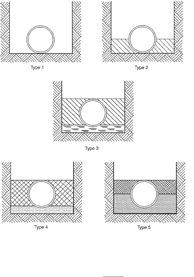
Example 6.4—30-in DI pipe. Calculate the thickness for 30-in ductile-iron
(DI) pipe laid on a flat-bottom trench with backfill tamped to centerline of
pipe, laying condition type 2 (Fig. 6.46 and Table 6.9), under 10 ft of cover
for a working pressure of 200 lb/in
2
. (See ductile iron section in Chap. 4 for
design procedure for pressure pipe). Also, see AWWA C150. Certain tables
(Tables 6.7 through 6.17) from AWWA C150 have been reproduced here for
the reader’s convenience. This example is taken from AWWA C150).
1. Design for trench load. First, earth load (Table 6.8) P
e
8.3 lb/in
2
may
be obtained from Fig. 2.19. Truck load (Table 6.8) P
t
0.7 lb/in
2
, and trench
load P
v
P
e
P
t
9.0 lb/in
2
.
Second, select Table 6.13 for diameter-thickness ratios for laying condi-
tion type 2. Third, entering the P
v
of 9.0 lb/in
2
in Table 6.13, we see that the
bending stress design requires a D/t of 128. From Table 6.12, diameter D of
30-in-OD pipe is 32.00 in. Net thickness t for bending stress is
t 0.25 in
Fourth, also from Table 6.13, the deflection design requires D/t
1
of 108.
Minimum thickness t
1
for deflection design is
t
1
0.30 in
32.0
108
D
D/t
1
32.0
128
D
D/t
Steel and Ductile Iron Flexible Pipe Products 337
TABLE 6.7 Selected Standards for Ductile Iron Pipe
AWWA C104 Cement mortar lining for ductile iron
AWWA C105 Polyethylene encasement for ductile iron
AWWA C110 Ductile iron and gray iron fittings
AWWA C111 Rubber-gasket joints for ductile iron
AWWA C115 Flanged ductile iron
AWWA C150 Thickness design of ductile iron pipe
AWWA C151 Ductile iron pipe in metal- and sand-lined molds
AWWA C600 Installation of ductile iron water mains and their appurtenances
ASTM E 8 Materials properties test
ASTM A 539 Physical properties
338 Chapter Six
Figure 6.46 Standard pipe-laying conditions. (Reprinted, by permission, from ANSI/AWWA
C-150/A21.50-96, American Water Works Association, 1996.)
Minimum thickness 0.30 in
Less service allowance
0.08 in
Net thickness t for deflection control 0.22 in
Fifth, the larger net thickness is 0.25 in, obtained by the design for bend-
ing stress.