Munson B.R. Fundamentals of Fluid Mechanics
Подождите немного. Документ загружается.

where is the fluid density, and V is the mean velocity in the tube.
Some experimental data obtained with
and are given in the following table:V ⫽ 2 ft
Ⲑ
s
r ⫽ 2.0 slugs
Ⲑ
ft
3
,D ⫽ 0.2 ft,
r
Problems
377
F I G U R E P7.30
0.06 0.08 0.10 0.15
493.8 156.2 64.0 12.6¢p 1lb
Ⲑ
ft
2
2
d 1ft2
D
V
d
Δp
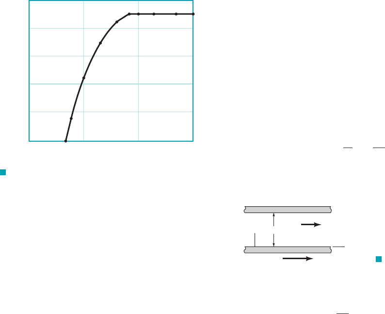
Plot the results of these tests, using suitable dimensionless parame-
ters, on log–log graph paper. Use a standard curve-fitting technique
to determine a general equation for . What are the limits of ap-
plicability of the equation?
¢p
mh, mH, m
2.0 0.10 0.833
4.0 0.10 0.833
2.0 0.20 0.417
4.0 0.20 0.417
2.0 0.35 0.238
4.0 0.35 0.238
/,
F I G U R E P7.32
CG
C
b
H
h
7.33 The time, t, it takes to pour a certain volume of liquid from a
cylindrical container depends on several factors, including the vis-
cosity of the liquid. (See Video V1.3.) Assume that for very viscous
liquids the time it takes to pour out 2/3 of the initial volume depends
on the initial liquid depth, the cylinder diameter, D, the liquid vis-
cosity, and the liquid specific weight, The data shown in theg.m,
/,
following table were obtained in the laboratory. For these tests
and (a) Perform a
dimensional analysis, and based on the data given, determine if vari-
ables used for this problem appear to be correct. Explain how you
arrived at your answer. (b) If possible, determine an equation relating
the pouring time and viscosity for the cylinder and liquids used in
these tests. If it is not possible, indicate what additional information
is needed.
g ⫽ 9.60 kN/m
3
.D ⫽ 67 mm,/ ⫽ 45 mm,
(N
•
s/m
2
) 11 17 39 61 107
15 23 53 83 145t1s2
7.34 In order to maintain uniform flight, smaller birds must beat
their wings faster than larger birds. It is suggested that the relation-
ship between the wingbeat frequency, , beats per second, and the
bird’s wingspan, , is given by a power law relationship,
(a) Use dimensional analysis with the assumption that the wingbeat
frequency is a function of the wingspan, the specific weight of the
bird, , the acceleration of gravity, g, and the density of the air, ,
to determine the value of the exponent . (b) Some typical data for
various birds are given in the table below. Does this data support
your result obtained in part (a)? Provide appropriate analysis to
show how you arrived at your conclusion.
n
r
a
g
v /
n
./
v
Wingbeat frequency,
Bird Wingspan, m beats/s
purple martin 0.28 5.3
robin 0.36 4.3
mourning dove 0.46 3.2
crow 1.00 2.2
Canada goose 1.50 2.6
great blue heron 1.80 2.0
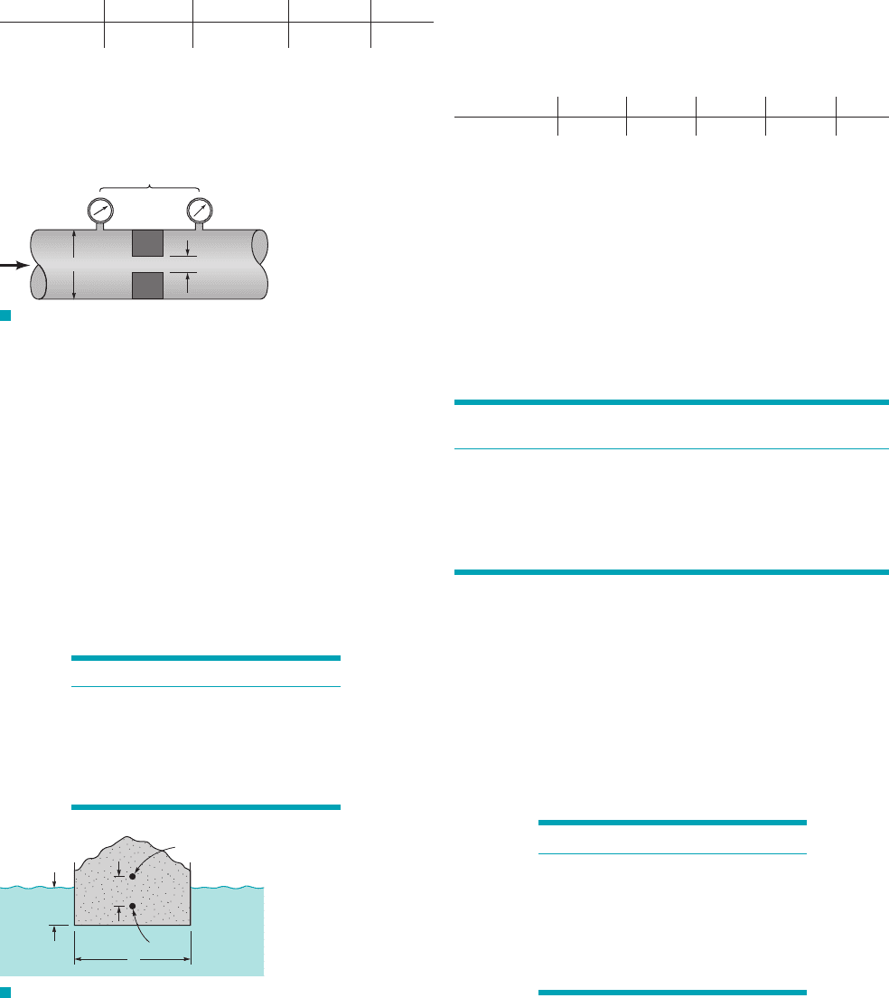
*7.35 The concentric cylinder device of the type shown in Fig.
P7.35 is commonly used to measure the viscosity, , of liquids by
relating the angle of twist, , of the inner cylinder to the angular ve-
locity, , of the outer cylinder. Assume that
where K depends on the suspending wire properties and has the di-
mensions FL. The following data were obtained in a series of tests
for which , , and and
were constant.D
2
D
1
/ ⫽ 1 ftm ⫽ 0.01 lb ⴢ s
Ⲑ
ft
2
, K ⫽ 10 lb ⴢ ft
u ⫽ f 1v, m, K, D
1
, D
2
, /2
v
u
m
(rad) (rad/s)
0.89 0.30
1.50 0.50
2.51 0.82
3.05 1.05
4.28 1.43
5.52 1.86
6.40 2.14
VU
Determine from these data, with the aid of dimensional analysis,
the relationship between , , and for this particular apparatus.
Hint: Plot the data using appropriate dimensionless parameters,
and determine the equation of the resulting curve using a standard
curve-fitting technique. The equation should satisfy the condition
that for .v ⫽ 0u ⫽ 0
mvu
*7.31 Describe some everyday situations involving fluid flow and
estimate the Reynolds numbers for them. Based on your results, do
you think fluid inertia is important in most typical flow situations?
Explain.
*7.32 As shown in Fig. 2.26, Fig. P7.32, and Video V2.10, a rec-
tangular barge floats in a stable configuration provided the dis-
tance between the center of gravity, CG, of the object (boat and
load) and the center of buoyancy, C, is less than a certain amount,
H. If this distance is greater than H, the boat will tip over. Assume
H is a function of the boat’s width, b, length, and draft, h. (a)
Put this relationship into dimensionless form. (b) The results of a
set of experiments with a model barge with a width of 1.0 m are
shown in the table. Plot these data in dimensionless form and
determine a power-law equation relating the dimensionless para-
meters.
/,
JWCL068_ch07_332-382.qxd 9/23/08 10:47 AM Page 377
Section 7.8 Modeling and Similitude
7.36 Obtain a photograph/image of a prototype and the corre-
sponding model that was used for testing. Print these photos and
write a brief paragraph that describes the situation involved.
7.37 Air at is to flow through a 2-ft pipe at an average veloc-
ity of 6 ft s. What size pipe should be used to move water at
and average velocity of 3 ft s if Reynolds number similarity is en-
forced?
7.38 To test the aerodynamics of a new prototype automobile, a
scale model will be tested in a wind tunnel. For dynamic similarity,
it will be required to match Reynolds number between model and
prototype. Assuming that you will be testing a one-tenth-scale
model and both model and prototype will be exposed to standard
air pressure, will it be better for the wind tunnel air to be colder or
hotter than standard sea-level air temperature of ? Why?
7.39 You are to conduct wind tunnel testing of a new football de-
sign that has a smaller lace height than previous designs (see
Videos V6.1 and V6.2). It is known that you will need to maintain
Re and St similarity for the testing. Based on standard college quar-
terbacks, the prototype parameters are set at and
The prototype football has a 7-in. diameter. Due to
instrumentation required to measure pressure and shear stress on
the surface of the football, the model will require a length scale of
2:1 (the model will be larger than the prototype). Determine the re-
quired model freestream velocity and model angular velocity.
7.40 A model of a submarine, 1 : 15 scale, is to be tested at 180 ft
s in a wind tunnel with standard sea-level air, while the prototype
will be operated in seawater. Determine the speed of the prototype
to ensure Reynolds number similarity.
7.41 SAE 30 oil at is pumped through a 3-ft-diameter
pipeline at a rate of A model of this pipeline is to be
designed using a 3-in.-diameter pipe and water at as the work-
ing fluid. To maintain Reynolds number similarity between these
two systems, what fluid velocity will be required in the model?
7.42 The water velocity at a certain point along a 1 : 10 scale
model of a dam spillway is 3 m s. What is the corresponding pro-
totype velocity if the model and prototype operate in accordance
with Froude number similarity?
7.43 The drag characteristics of a torpedo are to be studied in a
water tunnel using a 1 : 5 scale model. The tunnel operates with
freshwater at , whereas the prototype torpedo is to be used in20 °C
Ⲑ
60 °F
6400 gal
Ⲑ
min.
60 °F
Ⲑ
v ⫽ 300 rpm.
V ⫽ 40 mph
15 °C
Ⲑ
60 °F
Ⲑ
80 °F
378 Chapter 7 ■ Dimensional Analysis, Similitude, and Modeling
F I G U R E P7.35
Liquid
Rotating
outer cylinder
Wire
Fixed support
θ
ᐉ
D
1
D
2
Inner
cylinder
seawater at To correctly simulate the behavior of the pro-
totype moving with a velocity of 30 m兾s, what velocity is required
in the water tunnel?
7.44 For a certain fluid-flow problem it is known that both the
Froude number and the Weber number are important dimensionless
parameters. If the problem is to be studied by using a 1 : 15 scale
model, determine the required surface tension scale if the density
scale is equal to 1. The model and prototype operate in the same
gravitational field.
7.45 The fluid dynamic characteristics of an airplane flying
240 mph at 10,000 ft are to be investigated with the aid of a 1 : 20
scale model. If the model tests are to be performed in a wind tunnel
using standard air, what is the required air velocity in the wind tun-
nel? Is this a realistic velocity?
7.46 If an airplane travels at a speed of 1120 km兾hr at an altitude
of 15 km, what is the required speed at an altitude of 8 km to satisfy
Mach number similarity? Assume the air properties correspond to
those for the U.S. standard atmosphere.
7.47 (See Fluids in the News article “Modeling parachutes in a wa-
ter tunnel,” Section 7.8.1.) Flow characteristics for a 30-ft-diameter
prototype parachute are to be determined by tests of a 1-ft-diameter
model parachute in a water tunnel. Some data collected with the model
parachute indicate a drag of 17 lb when the water velocity is .
Use the model data to predict the drag on the prototype parachute
falling through air at . Assume the drag to be a function of the
velocity, V, the fluid density, , and the parachute diameter, D.
7.48 The lift and drag developed on a hydrofoil are to be deter-
mined through wind tunnel tests using standard air. If full-scale
tests are to be run, what is the required wind tunnel velocity corre-
sponding to a hydrofoil velocity in seawater at 15 mph? Assume
Reynolds number similarity is required.
7.49 A scale model is to be used in a towing tank to study the
water motion near the bottom of a shallow channel as a large barge
passes over. (See Video V7.16.) Assume that the model is operated
in accordance with the Froude number criteria for dynamic simili-
tude. The prototype barge moves at a typical speed of 15 knots.
(a)At what speed (in ) should the model be towed? (b) Near the
bottom of the model channel a small particle is found to move
0.15 ft in one second so that the fluid velocity at that point is ap-
proximately Determine the velocity at the corresponding
point in the prototype channel.
7.50 A solid sphere having a diameter d and specific weight is
immersed in a liquid having a specific weight and then
released. It is desired to use a model system to determine the max-
imum height, h, above the liquid surface that the sphere will rise
upon release from a depth H. It can be assumed that the important
liquid properties are the density, , specific weight, , and vis-
cosity, . Establish the model design conditions and the prediction
equation, and determine whether the same liquid can be used in
both the model and prototype systems.
7.51 A thin layer of an incompressible fluid flows steadily over a
horizontal smooth plate as shown in Fig. P7.51. The fluid surface is
open to the atmosphere, and an obstruction having a square cross
section is placed on the plate as shown. A model with a length scale
m
f
g
f
g
f
Ⲑ
g
g
f
1g
f
7 g
s
2
g
s
0.15 ft/s.
ft/s
1/50
r
10 ft
Ⲑ
s
4 ft
Ⲑ
s
15.6 °C.
F I G U R E P7.51
V
Free surface
JWCL068_ch07_332-382.qxd 9/23/08 10:47 AM Page 378
of and a fluid density scale of 1.0 is to be designed to predict the
depth of fluid, y, along the plate. Assume that inertial, gravitational,
surface tension, and viscous effects are all important. What are the
required viscosity and surface tension scales?
7.52 The drag on a 2-m-diameter satellite dish due to an 80-km hr
wind is to be determined through a wind tunnel test using a geomet-
rically similar 0.4-m-diameter model dish. Assume standard air for
both model and prototype. (a) At what air speed should the model
test be run? (b)With all similarity conditions satisfied, the measured
drag on the model was determined to be 170 N. What is the pre-
dicted drag on the prototype dish?
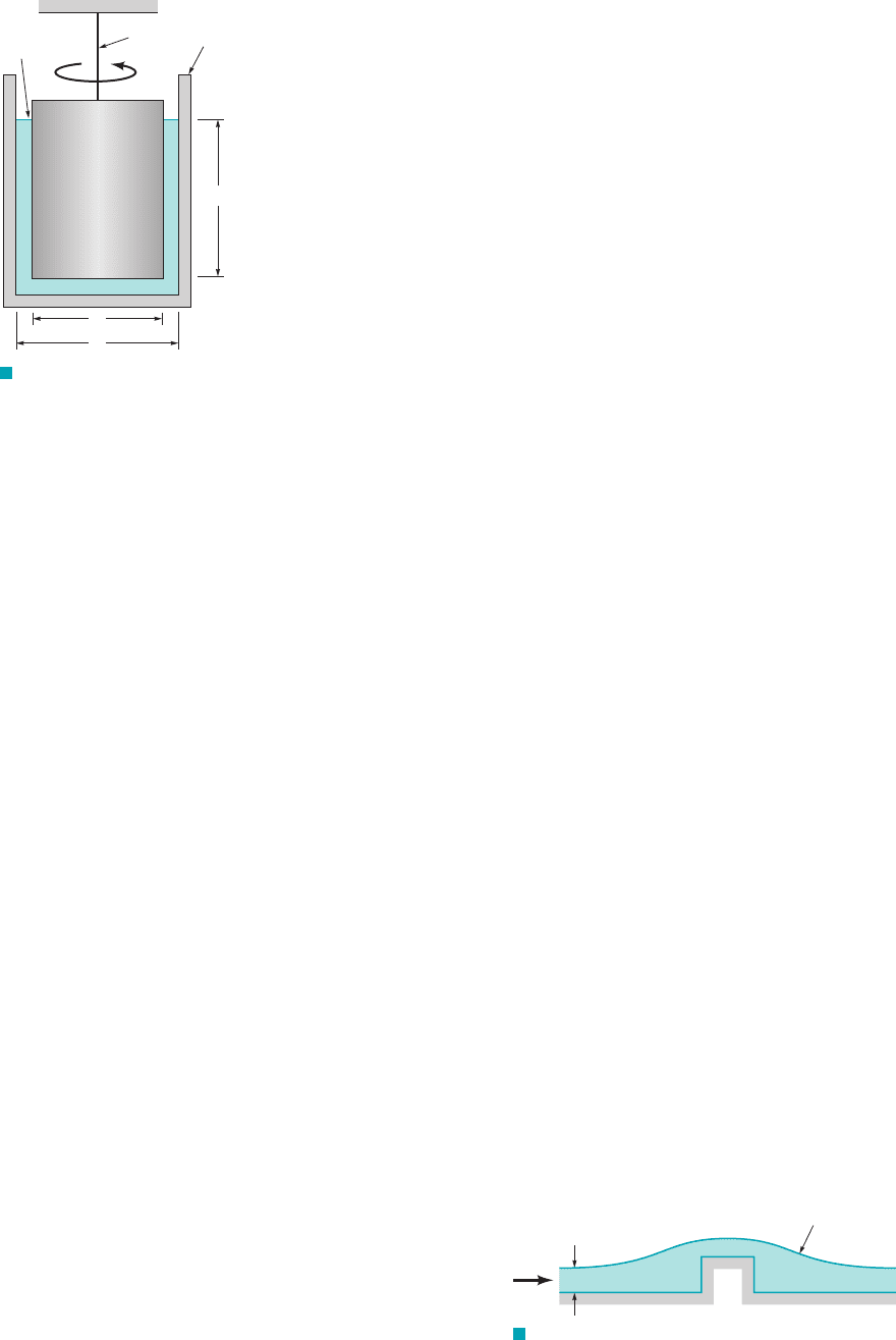
7.53 A large, rigid, rectangular billboard is supported by an elastic
column as shown in Fig. P7.53. There is concern about the deflec-
tion, , of the top of the structure during a high wind of velocity V.
A wind tunnel test is to be conducted with a 1 : 15 scale model. As-
sume the pertinent column variables are its length and cross-
sectional dimensions, and the modulus of elasticity of the material
used for the column. The only important “wind” variables are the
air density and velocity. (a) Determine the model design conditions
and the prediction equation for the deflection. (b) If the same struc-
tural materials are used for the model and prototype, and the wind
tunnel operates under standard atmospheric conditions, what is the
required wind tunnel velocity to match an 80 km hr wind?
Ⲑ
d
Ⲑ
1
4
Problems 379
F I G U R E P7.53
Billboard
V
Front View
Side View
δ
7.54 A thin flat plate having a diameter of 0.3 ft is towed through
a tank of oil at a velocity of . The plane of the
plate is perpendicular to the direction of motion, and the plate is
submerged so that wave action is negligible. Under these condi-
tions the drag on the plate is 1.4 lb. If viscous effects are neglected,
predict the drag on a geometrically similar, 2-ft-diameter plate that
is towed with a velocity of through water at under con-
ditions similar to those for the smaller plate.
7.55 For a certain model study involving a 1 : 5 scale model it is
known that Froude number similarity must be maintained. The pos-
sibility of cavitation is also to be investigated, and it is assumed that
the cavitation number must be the same for model and prototype.
The prototype fluid is water at and the model fluid is water at
If the prototype operates at an ambient pressure of 101 kPa
1abs2, what is the required ambient pressure for the model system?
7.56 A thin layer of particles rests on the bottom of a horizontal
tube as shown in Fig. P7.56. When an incompressible fluid flows
70 °C.
30 °C,
60 °F3 ft
Ⲑ
s
5 ft
Ⲑ
s1g ⫽ 53 lb
Ⲑ
ft
3
2
through the tube, it is observed that at some critical velocity the par-
ticles will rise and be transported along the tube. A model is to be
used to determine this critical velocity. Assume the critical velocity,
, to be a function of the pipe diameter, D, particle diameter, d, the
fluid density, , and viscosity, , the density of the particles, , and
the acceleration of gravity, g. (a) Determine the similarity require-
ments for the model, and the relationship between the critical
velocity for model and prototype (the prediction equation). (b) For
a length scale of and a fluid density scale of 1.0, what will be the
critical velocity scale (assuming all similarity requirements are
satisfied)?
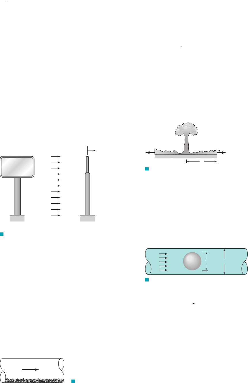
7.57 The pressure rise, across a blast wave, as shown in Fig.
P7.57 and Video V11.7, is assumed to be a function of the amount
of energy released in the explosion, E, the air density, the speed
of sound, c, and the distance from the blast, d. (a) Put this relation-
ship in dimensionless form. (b) Consider two blasts: the prototype
blast with energy release E and a model blast with the en-
ergy release At what distance from the model blast
will the pressure rise be the same as that at a distance of 1 mile from
the prototype blast?
1E
m
⫽ 0.001 E2.
1/1000th
r,
¢p,
1
2
r
p
mr
V
c
F I G U R E P7.56
V
c
F I G U R E P7.57
Air ( , c)
ρ
(2)
Δp = p
2
– p
1
(1)
d
7.58 The drag, on a sphere located in a pipe through which a
fluid is flowing is to be determined experimentally 1see Fig. P7.582.
Assume that the drag is a function of the sphere diameter, d, the
pipe diameter, D, the fluid velocity, V, and the fluid density, (a)
What dimensionless parameters would you use for this problem?
(b) Some experiments using water indicate that for
and the drag is If possible,
estimate the drag on a sphere located in a 2-ft-diameter pipe
through which water is flowing with a velocity of 6 ft兾s. The sphere
diameter is such that geometric similarity is maintained. If it is not
possible, explain why not.
1.5 ⫻ 10
⫺3
lb.V ⫽ 2 ft
Ⲑ
s,D ⫽ 0.5 in.,
d ⫽ 0.2 in.,
r.
d,
F I G U R E P7.58
V
dD
Sphere
7.59 An incompressible fluid oscillates harmonically (
where V is the velocity) with a frequency of 10 rad s in a
4-in.-diameter pipe. scale model is to be used to determine the
pressure difference per unit length, (at any instant) along the
pipe. Assume that
where D is the pipe diameter, the frequency, t the time, the fluid
viscosity, and the fluid density. (a) Determine the similarity re-
quirements for the model and the prediction equation for . (b) If
the same fluid is used in the model and the prototype, at what fre-
quency should the model operate?
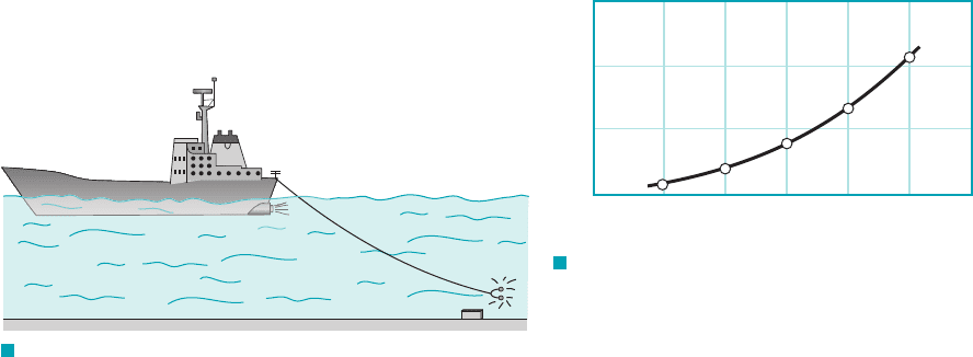
7.60 As shown in Fig. P7.60, a “noisemaker” B is towed behind a
minesweeper A to set off enemy acoustic mines such as at C. The
drag force of the noisemaker is to be studied in a water tunnel at a
1
⁄4 scale model (model
1
⁄4 the size of the prototype). The drag force is
¢p
/
r
mv
¢p
/
⫽ f 1D, V
0
, v, t, m, r2
¢p
/
A
1
4
Ⲑ
V
0
sin vt,
V ⫽
JWCL068_ch07_332-382.qxd 9/30/08 8:23 AM Page 379
assumed to be a function of the speed of the ship, the density and
viscosity of the fluid, and the diameter of the noisemaker. (a) If the
prototype towing speed in 3 m s, determine the water velocity in
the tunnel for the model tests. (b) If the model tests of part (a) pro-
duced a model drag of 900 N, determine the drag expected on the
prototype.
Ⲑ
380 Chapter 7 ■ Dimensional Analysis, Similitude, and Modeling
C
B
A
F I G U R E P7.60
6
4
2
0
0 2 4 6 8 10 12
Model velocity, ft/s
Model drag,lb
F I G U R E P7.65
7.61 The drag characteristics for a newly designed automobile
having a maximum characteristic length of 20 ft are to be deter-
mined through a model study. The characteristics at both low speed
1approximately 20 mph2and high speed 190 mph2are of interest. For
a series of projected model tests, an unpressurized wind tunnel that
will accommodate a model with a maximum characteristic length
of 4 ft is to be used. Determine the range of air velocities that would
be required for the wind tunnel if Reynolds number similarity is de-
sired. Are the velocities suitable? Explain.
7.62 The drag characteristics of an airplane are to be determined
by model tests in a wind tunnel operated at an absolute pressure of
1300 kPa. If the prototype is to cruise in standard air at 385 km兾hr,
and the corresponding speed of the model is not to differ by more
than 20% from this 1so that compressibility effects may be ignored2,
what range of length scales may be used if Reynolds number simi-
larity is to be maintained? Assume the viscosity of air is unaffected
by pressure, and the temperature of air in the tunnel is equal to the
temperature of the air in which the airplane will fly.
7.63 Wind blowing past a flag causes it to “flutter in the breeze.”
The frequency of this fluttering, is assumed to be a function of
the wind speed, V, the air density, the acceleration of gravity, g,
the length of the flag, and the “area density,” 1with dimensions
of 2of the flag material. It is desired to predict the flutter fre-
quency of a large flag in a wind. To do this a
model flag with is to be tested in a wind tunnel. (a) Deter-
mine the required area density of the model flag material if the large
flag has (b) What wind tunnel velocity is re-
quired for testing the model? (c) If the model flag flutters at 6 Hz,
predict the frequency for the large flag.
†7.64 If a large oil spill occurs from a tanker operating near a
coastline, the time it would take for the oil to reach shore is of
great concern. Design a model system that can be used to investi-
gate this type of problem in the laboratory. Indicate all assump-
tions made in developing the design and discuss any difficulty that
may arise in satisfying the similarity requirements arising from
your model design.
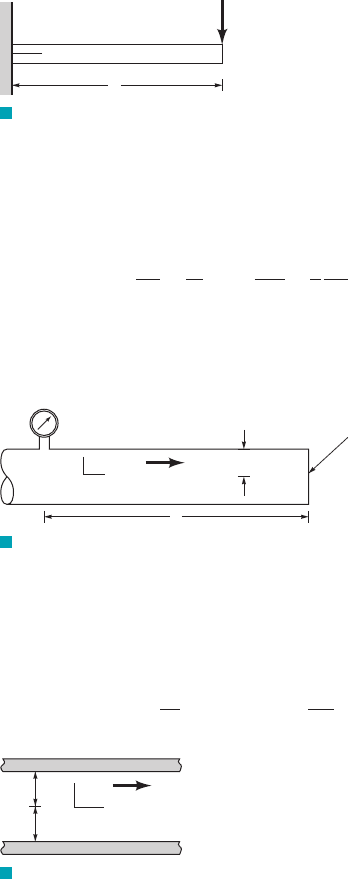
7.65 The drag on a sphere moving in a fluid is known to be a func-
tion of the sphere diameter, the velocity, and the fluid viscosity and
density. Laboratory tests on a 4-in.-diameter sphere were performed
in a water tunnel and some model data are plotted in Fig. P7.65.
For these tests the viscosity of the water was
and the water density was . Estimate the drag on an
8-ft-diameter balloon moving in air at a velocity of . Assume3 ft
Ⲑ
s
1.94 slugs
Ⲑ
ft
3
2.3 ⫻ 10
⫺5
lb
#
s
Ⲑ
ft
2
r
A
⫽ 0.006 slugs
Ⲑ
ft
2
.
/ ⫽ 4 ft
V ⫽ 30 ft
Ⲑ
s/ ⫽ 40 ft
ML
⫺2
r
A
/,
r,
v,
Section 7.9 Some Typical Model Studies
7.66 Obtain a photograph/image of a situation where a flow
around an immersed body is being experimentally tested. Print this
photo and write a brief paragraph that describes the situation in-
volved.
7.67 Drag measurements were taken for a sphere, with a diameter
of 5 cm, moving at 4 m s in water at . The resulting drag on
the sphere was 10 N. For a balloon with 1-m diameter rising in air
with standard temperature and pressure, determine (a) the velocity
if Reynolds number similarity is enforced and (b) the drag force if
the drag coefficient (Eq. 7.19) is the dependent pi term.
7.68 A prototype automobile is designed to travel at 65 km hr. A
model of this design is tested in a wind tunnel with identical stan-
dard sea-level air properties at a 1: 5 scale. The measured model
drag is 400 N, enforcing dynamic similarity. Determine (a) the drag
force on the prototype and (b) the power required to overcome this
drag. See Eq. 7.19.
7.69 A new blimp will move at 6 m s in air, and we want to
predict the drag force. Using a 1 : 13-scale model in water at
and measuring a 2500-N drag force on the model, determine (a) the
required water velocity, (b) the drag on the prototype blimp and, (c)
the power that will be required to propel it through the air.
7.70 At a large fish hatchery the fish are reared in open, water-filled
tanks. Each tank is approximately square in shape with curved cor-
ners, and the walls are smooth. To create motion in the tanks, water
is supplied through a pipe at the edge of the tank. The water is
drained from the tank through an opening at the center. (See Video
V7.9.) A model with a length scale of 1 13 is to be used to deter-
mine the velocity, V, at various locations within the tank. Assume
that V ⫽ f (, , , ,g, Q) where is some characteristic length
such as the tank width, represents a series of other pertinent
lengths, such as inlet pipe diameter, fluid depth, etc., is the fluid
density, is the fluid viscosity, g is the acceleration of gravity, and
Q is the discharge through the tank. (a) Determine a suitable set of
dimensionless parameters for this problem and the prediction equa-
tion for the velocity. If water is to be used for the model, can all of
the similarity requirements be satisfied? Explain and support your
answer with the necessary calculations. (b) If the flowrate into the
full-sized tank is 250 gpm, determine the required value for the
model discharge assuming Froude number similarity. What model
depth will correspond to a depth of 32 in. in the full-sized tank?
7.71 Flow patterns that develop as winds blow past a vehicle, such
as a train, are often studied in low-speed environmental (meteoro-
logical) wind tunnels. (See Video V7.16.) Typically, the air veloci-
ties in these tunnels are in the range of to Consider
a cross wind blowing past a train locomotive. Assume that the local
30 m/s.0.1 m/s
m
r
/
i
/mr/
i
/
20 °C
20 °C
Ⲑ
Ⲑ
20 °C
Ⲑ
the air to have a viscosity of and a density of
.2.38 ⫻ 10
⫺3
slugs
Ⲑ
ft
3
3.7 ⫻ 10
⫺7
lb
#
s
Ⲑ
ft
2
JWCL068_ch07_332-382.qxd 9/30/08 3:39 PM Page 380
wind velocity, V, is a function of the approaching wind velocity (at
some distance from the locomotive), U, the locomotive length,
height, h, and width, b, the air density, and the air viscosity, (a)
Establish the similarity requirements and prediction equation for a
model to be used in the wind tunnel to study the air velocity, V,
around the locomotive. (b) If the model is to be used for cross winds
gusting to explain why it is not practical to maintain
Reynolds number similarity for a typical length scale 1⬊50.
7.72 (See Fluids in the News article titled “Galloping Gertie,” Sec-
tion 7.8.2.) The Tacoma Narrows bridge failure is a dramatic exam-
ple of the possible serious effects of wind-induced vibrations. As a
fluid flows around a body, vortices may be created which are shed
periodically creating an oscillating force on the body. If the fre-
quency of the shedding vortices coincides with the natural frequency
of the body, large displacements of the body can be induced as was
the case with the Tacoma Narrows bridge. To illustrate this type of
phenomenon, consider fluid flow past a circular cylinder. Assume
the frequency, n, of the shedding vortices behind the cylinder is a
function of the cylinder diameter, D, the fluid velocity, V, and the
fluid kinematic viscosity, . (a) Determine a suitable set of dimen-
sionless variables for this problem. One of the dimensionless vari-
ables should be the Strouhal number, . (b) Some results of ex-
periments in which the shedding frequency of the vortices (in Hz)
was measured, using a particular cylinder and Newtonian, incom-
pressible fluid, are shown in Fig. P7.72. Is this a “universal curve”
that can be used to predict the shedding frequency for any cylinder
placed in any fluid? Explain. (c) A certain structural component in
the form of a 1-in.-diameter, 12-ft-long rod acts as a cantilever beam
with a natural frequency of 19 Hz. Based on the data in Fig. P7.72,
estimate the wind speed that may cause the rod to oscillate at its
natural frequency. Hint: Use a trial and error solution.
nD
Ⲑ
V
n
U ⫽ 25 m
Ⲑ
s,
m.r,
/,
Problems
381
0.22
0.20
0.18
0.16
0.14
0.12
10 100 1,000 10,000
Re =VD/v
St=nD/V
F I G U R E P7.72
7.73 (See Fluids in the News article titled “Ice engineering,” Sec-
tion 7.9.3.) A model study is to be developed to determine the force
exerted on bridge piers due to floating chunks of ice in a river. The
piers of interest have square cross sections. Assume that the force,
R, is a function of the pier width, b, the depth of the ice, d, the ve-
locity of the ice, V, the acceleration of gravity, g, the density of the
ice, , and a measure of the strength of the ice, , where has the
dimensions (a) Based on these variables determine a suitable
set of dimensionless variables for this problem. (b) The prototype
conditions of interest include an ice thickness of 12 in. and an ice
velocity of . What model ice thickness and velocity would be
required if the length scale is to be 1 10? (c) If the model and pro-
totype ice have the same density, can the model ice have the same
strength properties as that of the prototype ice? Explain.
Ⲑ
6 ft
Ⲑ
s
FL
⫺2
.
E
i
E
i
r
i
7.74 As illustrated in Video V7.9, models are commonly used to
study the dispersion of a gaseous pollutant from an exhaust stack
located near a building complex. Similarity requirements for the pol-
lutant source involve the following independent variables: the stack
gas speed, V, the wind speed, U, the density of the atmospheric air,
the difference in densities between the air and the stack gas,
the acceleration of gravity, g, the kinematic viscosity of the
stack gas, and the stack diameter, D. (a) Based on these variables,
determine a suitable set of similarity requirements for modeling the
pollutant source. (b) For this type of model a typical length scale
might be 1⬊200. If the same fluids were used in model and proto-
type, would the similarity requirements be satisfied? Explain and
support your answer with the necessary calculations.
7.75 River models are used to study many different types of flow
situations. (See, for example, Video V7.12.) A certain small river
has an average width and depth of 60 ft and 4 ft, respectively, and
carries water at a flowrate of A model is to be designed
based on Froude number similarity so that the discharge scale is
1兾250. At what depth and flowrate would the model operate?
7.76 As winds blow past buildings, complex flow patterns can de-
velop due to various factors such as flow separation and interactions
between adjacent buildings. (See Video V7.13.) Assume that the lo-
cal gage pressure, p, at a particular loaction on a building is a func-
tion of the air density, the wind speed, V, some characteristic
length, and all other pertinent lengths, needed to characterize
the geometry of the building or building complex. (a) Determine a
suitable set of dimensionless parameters that can be used to study
the pressure distribution. (b) An eight-story building that is 100 ft
tall is to be modeled in a wind tunnel. If a length scale of 1⬊300 is to
be used, how tall should the model building be? (c) How will a mea-
sured pressure in the model be related to the corresponding proto-
type pressure? Assume the same air density in model and prototype.
Based on the assumed variables, does the model wind speed have to
be equal to the prototype wind speed? Explain.
Section 7.10 Similitude Based on Governing
Differential Equations
7.77 Start with the two-dimensional continuity equation and the
Navier–Stokes equations 1Eqs. 7.28, 7.29, and 7.302and verify the
nondimensional forms of these equations 1Eqs. 7.31, 7.34, and 7.352.
7.78 A viscous fluid is contained between wide, parallel plates
spaced a distance h apart as shown in Fig. P7.78. The upper plate is
fixed, and the bottom plate oscillates harmonically with a velocity
amplitude U and frequency The differential equation for the
velocity distribution between the plates is
where u is the velocity, t is time, and and are fluid density and
viscosity, respectively. Rewrite this equation in a suitable nondi-
mensional form using h, U, and as reference parameters.v
mr
r
0u
0t
⫽ m
0
2
u
0y
2
v.
/
i
,/,
r,
700 ft
3
/s.
v
s
,
r ⫺ r
s
,
r,
F I G U R E P7.78
y
h
u
u
= Ucos t
ω
x
Fixed plate
7.79 The deflection of the cantilever beam of Fig. P7.79 is gov-
erned by the differential equation
EI
d
2
y
dx
2
⫽ P1x ⫺ / 2
JWCL068_ch07_332-382.qxd 9/23/08 10:47 AM Page 381
where E is the modulus of elasticity and I is the moment of inertia
of the beam cross section. The boundary conditions are at
and at (a) Rewrite the equation and
boundary conditions in dimensionless form using the beam length,
as the reference length. (b) Based on the results of part 1a2, what
are the similarity requirements and the prediction equation for a
model to predict deflections?
/,
x ⫽ 0.dy
Ⲑ
dx ⫽ 0x ⫽ 0
y ⫽ 0
382 Chapter 7 ■ Dimensional Analysis, Similitude, and Modeling
F I G U R E P7.80
x
P
y
ᐉ
F I G U R E P7.79
p
1
r
z
End initially
closed
v
z
R
ᐉ
F I G U R E P7.81
h
h
u
x
y
7.81 An incompressible fluid is contained between two infinite
parallel plates as illustrated in Fig. P7.81. Under the influence of a
harmonically varying pressure gradient in the x direction, the fluid
oscillates harmonically with a frequency The differential equa-
tion describing the fluid motion is
r
0u
0t
⫽ X cos vt ⫹ m
0
2
u
0y
2
v.
where X is the amplitude of the pressure gradient. Express this
equation in nondimensional form using h and as reference para-
meters.
■ Lab Problems
7.82 This problem involves the time that it takes water to drain
from two geometrically similar tanks. To proceed with this problem,
go to the book’s web site, www.wiley.com/college/munson.
7.83 This problem involves determining the frequency of vortex
shedding from a circular cylinder as water flows past it. To proceed
with this problem, go to the book’s web site, www.wiley.com/
college/munson.
7.84 This problem involves the determination of the head loss for
flow through a valve. To proceed with this problem, go to the
book’s web site, www.wiley.com/college/munson.
7.85 This problem involves the calibration of a rotameter. To pro-
ceed with this problem, go to the book’s web site, www.wiley.com/
college/munson.
■ Life Long Learning Problems
7.86 Microfluidics is the study of fluid flow in fabricated devices
at the micro scale. Advances in microfluidics have enhanced the
ability of scientists and engineers to perform laboratory experi-
ments using miniaturized devices known as a “lab-on-a-chip.” Ob-
tain information about a lab-on-a-chip device that is available com-
mercially and investigate its capabilities. Summarize your findings
in a brief report.
7.87 For some types of aerodynamic wind tunnel testing, it is dif-
ficult to simultaneously match both the Reynolds number and
Mach number between model and prototype. Engineers have de-
veloped several potential solutions to the problem including pres-
surized wind tunnels and lowering the temperature of the flow.
Obtain information about cryogenic wind tunnels and explain the
advantages and disadvantages. Summarize your findings in a brief
report.
■ FlowLab Problems
*7.88 This FlowLab problem involves investigation of the
Reynolds number significance in fluid dynamics through the sim-
ulation of flow past a cylinder. To proceed with this problem, go to
the book’s web site, www.wiley.com/college/munson.
■ FE Exam Problems
Sample FE (Fundamental of Engineering) exam questions for fluid
mechanics are provided on the book’s web site, www.wiley.com/
college/munson.
v
7.80 A liquid is contained in a pipe that is closed at one end as
shown in Fig. P7.80. Initially the liquid is at rest, but if the end is
suddenly opened the liquid starts to move. Assume the pressure
remains constant. The differential equation that describes the re-
sulting motion of the liquid is
where is the velocity at any radial location, r, and t is time. Rewrite
this equation in dimensionless form using the liquid density, the
viscosity, and the pipe radius, R, as reference parameters.m,
r,
v
z
r
0v
z
0t
⫽
p
1
/
⫹ m a
0
2
v
z
0r
2
⫹
1
r
0v
z
0r
b
p
1
JWCL068_ch07_332-382.qxd 9/23/08 10:47 AM Page 382

383
CHAPTER OPENING PHOTO: Turbulent jet: The jet of water from the pipe is turbulent. The complex, irregular,
unsteady structure typical of turbulent flows is apparent. (Laser-induced fluorescence of dye in water.) (Pho-
tography by P. E. Dimotakis, R. C. Lye, and D. Z. Papantoniou.)
Learning Objectives
After completing this chapter, you should be able to:
■ identify and understand various characteristics of the flow in pipes.
■ discuss the main properties of laminar and turbulent pipe flow and appreciate
their differences.
■ calculate losses in straight portions of pipes as well as those in various
pipe system components.
■ apply appropriate equations and principles to analyze a variety of pipe
flow situations.
■ predict the flowrate in a pipe by use of common flowmeters.
In the previous chapters we have considered a variety of topics concerning the motion of fluids.
The basic governing principles concerning mass, momentum, and energy were developed and ap-
plied, in conjunction with rather severe assumptions, to numerous flow situations. In this chapter
we will apply the basic principles to a specific, important topic—the incompressible flow of vis-
cous fluids in pipes and ducts.
The transport of a fluid 1liquid or gas2in a closed conduit 1commonly called a pipe if it is of
round cross section or a duct if it is not round2is extremely important in our daily operations. A brief
consideration of the world around us will indicate that there is a wide variety of applications of pipe
flow. Such applications range from the large, man-made Alaskan pipeline that carries crude oil al-
most 800 miles across Alaska, to the more complex 1and certainly not less useful2natural systems of
“pipes” that carry blood throughout our body and air into and out of our lungs. Other examples
8
8
V
iscous Flow
in Pipes
V
iscous Flow
in Pipes
Pipe flow is very
important in our
daily operations.
V8.1 Turbulent jet
JWCL068_ch08_383-460.qxd 9/23/08 10:50 AM Page 383
include the water pipes in our homes and the distribution system that delivers the water from the
city well to the house. Numerous hoses and pipes carry hydraulic fluid or other fluids to various
components of vehicles and machines. The air quality within our buildings is maintained at com-
fortable levels by the distribution of conditioned 1heated, cooled, humidified兾dehumidified2air
through a maze of pipes and ducts. Although all of these systems are different, the fluid mechan-
ics principles governing the fluid motions are common. The purpose of this chapter is to under-
stand the basic processes involved in such flows.
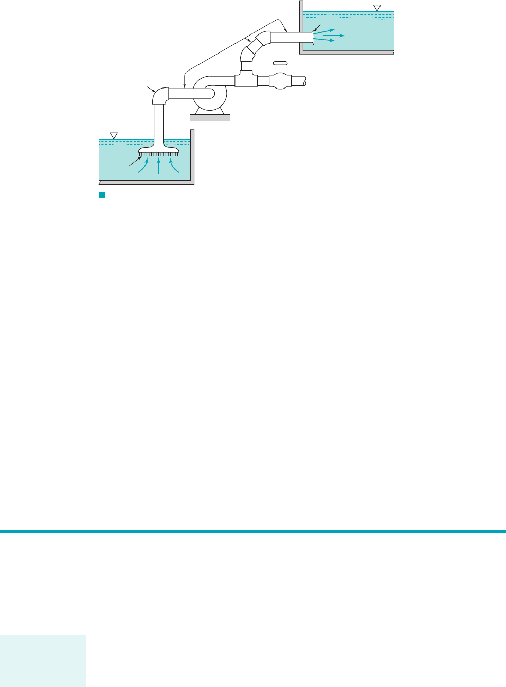
Some of the basic components of a typical pipe system are shown in Fig. 8.1. They include
the pipes themselves 1perhaps of more than one diameter2, the various fittings used to connect the
individual pipes to form the desired system, the flowrate control devices 1valves2, and the pumps
or turbines that add energy to or remove energy from the fluid. Even the most simple pipe systems
are actually quite complex when they are viewed in terms of rigorous analytical considerations.
We will use an “exact” analysis of the simplest pipe flow topics 1such as laminar flow in long,
straight, constant diameter pipes2and dimensional analysis considerations combined with experi-
mental results for the other pipe flow topics. Such an approach is not unusual in fluid mechanics
investigations. When “real-world” effects are important 1such as viscous effects in pipe flows2, it
is often difficult or “impossible” to use only theoretical methods to obtain the desired results. A
judicious combination of experimental data with theoretical considerations and dimensional analy-
sis often provides the desired results. The flow in pipes discussed in this chapter is an example of
such an analysis.
384 Chapter 8 ■ Viscous Flow in Pipes
F I G U R E 8.1 Typical pipe system components.
Pump
Tee
Valve
Outlet
Elbow
Inlet
Pipe
Before we apply the various governing equations to pipe flow examples, we will discuss some of
the basic concepts of pipe flow. With these ground rules established we can then proceed to for-
mulate and solve various important flow problems.
Although not all conduits used to transport fluid from one location to another are round in
cross section, most of the common ones are. These include typical water pipes, hydraulic hoses, and
other conduits that are designed to withstand a considerable pressure difference across their walls
without undue distortion of their shape. Typical conduits of noncircular cross section include heat-
ing and air conditioning ducts that are often of rectangular cross section. Normally the pressure dif-
ference between the inside and outside of these ducts is relatively small. Most of the basic princi-
ples involved are independent of the cross-sectional shape, although the details of the flow may be
dependent on it. Unless otherwise specified, we will assume that the conduit is round, although we
will show how to account for other shapes.
8.1 General Characteristics of Pipe Flow
The pipe is as-
sumed to be com-
pletely full of the
flowing fluid.
JWCL068_ch08_383-460.qxd 9/23/08 10:50 AM Page 384
For all flows involved in this chapter, we assume that the pipe is completely filled with the
fluid being transported as is shown in Fig. 8.2a. Thus, we will not consider a concrete pipe through
which rainwater flows without completely filling the pipe, as is shown in Fig. 8.2b. Such flows,
called open-channel flow, are treated in Chapter 10. The difference between open-channel flow and
the pipe flow of this chapter is in the fundamental mechanism that drives the flow. For open-chan-
nel flow, gravity alone is the driving force—the water flows down a hill. For pipe flow, gravity
may be important 1the pipe need not be horizontal2, but the main driving force is likely to be a
pressure gradient along the pipe. If the pipe is not full, it is not possible to maintain this pressure
difference,
8.1.1 Laminar or Turbulent Flow
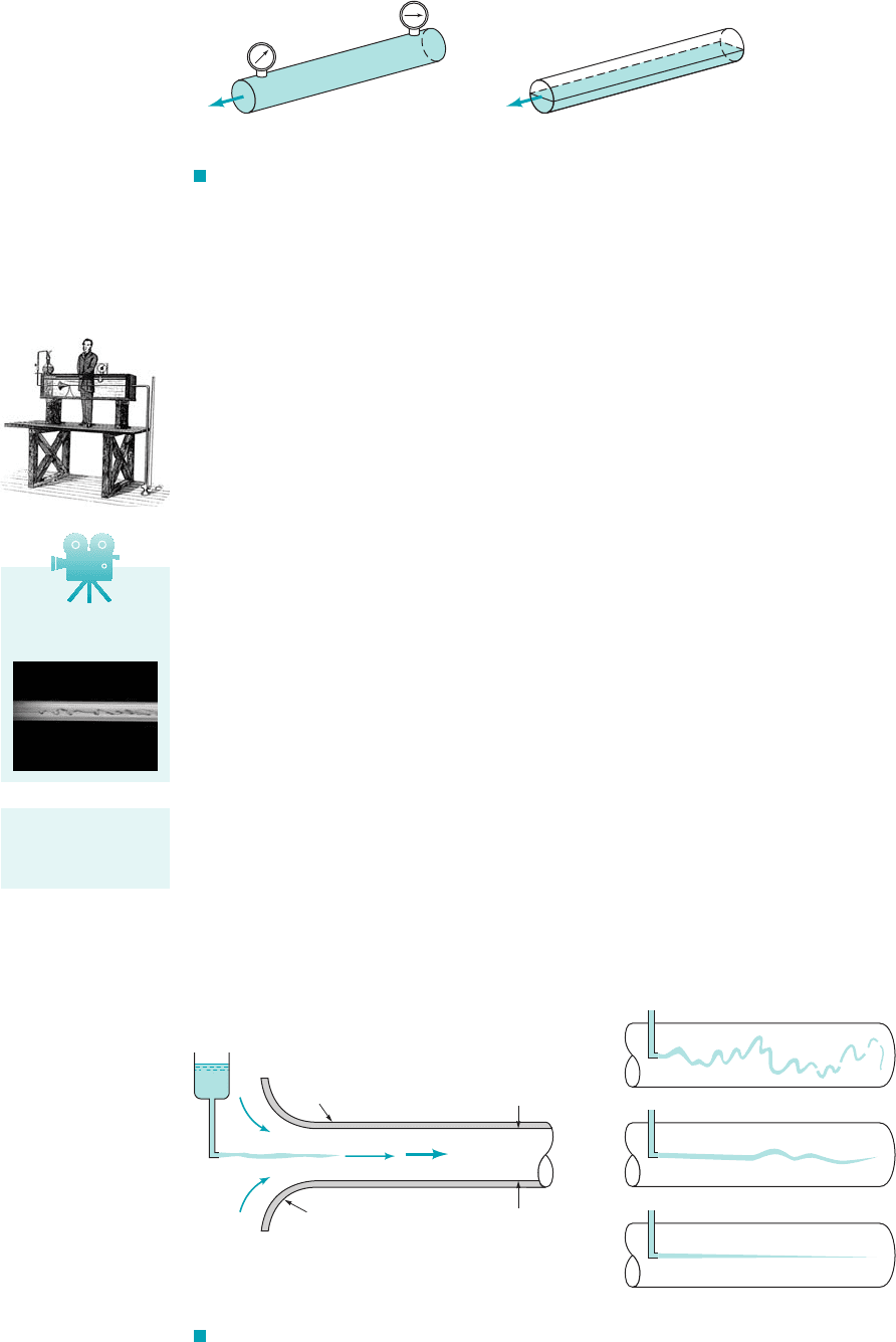
The flow of a fluid in a pipe may be laminar flow or it may be turbulent flow. Osborne Reynolds
11842–19122, a British scientist and mathematician, was the first to distinguish the difference be-
tween these two classifications of flow by using a simple apparatus as shown by the figure in the
margin, which is a sketch of Reynolds’ dye experiment. Reynolds injected dye into a pipe in which
water flowed due to gravity. The entrance region of the pipe is depicted in Fig. 8.3a. If water runs
through a pipe of diameter D with an average velocity V, the following characteristics are ob-
served by injecting neutrally buoyant dye as shown. For “small enough flowrates” the dye streak
1a streakline2will remain as a well-defined line as it flows along, with only slight blurring due to
molecular diffusion of the dye into the surrounding water. For a somewhat larger “intermediate
flowrate” the dye streak fluctuates in time and space, and intermittent bursts of irregular behav-
ior appear along the streak. On the other hand, for “large enough flowrates” the dye streak al-
most immediately becomes blurred and spreads across the entire pipe in a random fashion. These
three characteristics, denoted as laminar, transitional, and turbulent flow, respectively, are illus-
trated in Fig. 8.3b.
The curves shown in Fig. 8.4 represent the x component of the velocity as a function of
time at a point A in the flow. The random fluctuations of the turbulent flow 1with the associated
particle mixing2are what disperse the dye throughout the pipe and cause the blurred appearance
illustrated in Fig. 8.3b. For laminar flow in a pipe there is only one component of velocity,
p
1
⫺ p
2
.
8.1 General Characteristics of Pipe Flow 385
V8.2 Laminar/
turbulent pipe flow
A flow may be lam-
inar, transitional,
or turbulent.
(2)
(
a)(b)
(1)
(2)
(1)
QQ
p
2
≠ p
1
p
1
= p
2
F I G U R E 8.2 (a) Pipe flow. (b) Open-channel flow.
Q = VA
D
Dye streak
Dye
Smooth, well-rounded
entrance
Pipe
(
a)(b)
Laminar
Transitional
Turbulent
F I G U R E 8.3 (a) Experiment to illustrate type of flow. (b) Typical dye streaks.
JWCL068_ch08_383-460.qxd 9/23/08 10:50 AM Page 385
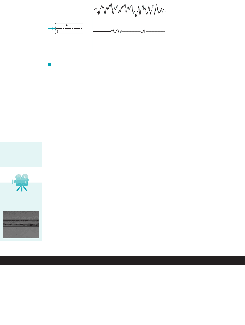
For turbulent flow the predominant component of velocity is also along the pipe, but it
is unsteady 1random2and accompanied by random components normal to the pipe axis,
Such motion in a typical flow occurs too fast for our eyes to follow. Slow
motion pictures of the flow can more clearly reveal the irregular, random, turbulent nature of the
flow.
As was discussed in Chapter 7, we should not label dimensional quantities as being “large”
or “small,” such as “small enough flowrates” in the preceding paragraphs. Rather, the appropriate
dimensionless quantity should be identified and the “small” or “large” character attached to it. A
quantity is “large” or “small” only relative to a reference quantity. The ratio of those quantities re-
sults in a dimensionless quantity. For pipe flow the most important dimensionless parameter is the
Reynolds number, Re—the ratio of the inertia to viscous effects in the flow. Hence, in the previ-
ous paragraph the term flowrate should be replaced by Reynolds number, where V
is the average velocity in the pipe. That is, the flow in a pipe is laminar, transitional, or turbulent
provided the Reynolds number is “small enough,” “intermediate,” or “large enough.” It is not only
the fluid velocity that determines the character of the flow—its density, viscosity, and the pipe size
are of equal importance. These parameters combine to produce the Reynolds number. The distinc-
tion between laminar and turbulent pipe flow and its dependence on an appropriate dimensionless
quantity was first pointed out by Osborne Reynolds in 1883.
The Reynolds number ranges for which laminar, transitional, or turbulent pipe flows are ob-
tained cannot be precisely given. The actual transition from laminar to turbulent flow may take place
at various Reynolds numbers, depending on how much the flow is disturbed by vibrations of the pipe,
roughness of the entrance region, and the like. For general engineering purposes 1i.e., without undue
precautions to eliminate such disturbances2, the following values are appropriate: The flow in a round
pipe is laminar if the Reynolds number is less than approximately 2100. The flow in a round pipe is
turbulent if the Reynolds number is greater than approximately 4000. For Reynolds numbers between
these two limits, the flow may switch between laminar and turbulent conditions in an apparently ran-
dom fashion 1transitional flow2.
Re ⫽ rVD
Ⲑ
m,
V ⫽ ui
ˆ
⫹ vj
ˆ
⫹ wk
ˆ
.
V ⫽ ui
ˆ
.
386 Chapter 8 ■ Viscous Flow in Pipes
F I G U R E 8.4 Time dependence of fluid velocity at a point.
Q
A
x
u
A
t
Laminar
Transitional
Turbulent
Fluids in the News
Nanoscale flows The term nanoscale generally refers to objects
with characteristic lengths from atomic dimensions up to a few hun-
dred nanometers (nm). (Recall that .) Nanoscale
fluid mechanics research has recently uncovered many surprising
and useful phenomena. No doubt many more remain to be discov-
ered. For example, in the future researchers envision using
nanoscale tubes to push tiny amounts of water-soluble drugs to ex-
actly where they are needed in the human body. Because of the tiny
diameters involved, the Reynolds numbers for such flows are ex-
tremely small and the flow is definitely laminar. In addition, some
1 nm ⫽ 10
⫺9
m
standard properties of everyday flows (for example, the fact that a
fluid sticks to a solid boundary) may not be valid for nanoscale
flows. Also, ultratiny mechanical pumps and valves are difficult to
manufacture and may become clogged by tiny particles such as bio-
logical molecules. As a possible solution to such problems, re-
searchers have investigated the possibility of using a system that
does not rely on mechanical parts. It involves using light-sensitive
molecules attached to the surface of the tubes. By shining light onto
the molecules, the light-responsive molecules attract water and
cause motion of water through the tube. (See Problem 8.10.)
Pipe flow character-
istics are dependent
on the value of the
Reynolds number.
V8.3 Intermittent
turbulent burst in
pipe flow
JWCL068_ch08_383-460.qxd 9/23/08 10:50 AM Page 386