Neamen D. Microelectronics: Circuit Analysis and Design
Подождите немного. Документ загружается.

338 Part 1 Semiconductor Devices and Basic Applications
while the collector current is
I
CQ
= β I
BQ
, and the collector–emitter voltage is given by
V
CEQ
= V
CC
− I
CQ
R
C
+
1 + β
β
R
E
The Q-point values for three values of
β
are shown in the following table.
Comment: The Q-point in this example is now considered to be stabilized against
variations in
β
, and the voltage divider resistors
R
1
and
R
2
have reasonable values in
the kilohm range. We see that the collector current changes by only
−8.2
percent
when
β
changes by a factor of 2 (from 120 to 60), and changes by only
+3.0
percent
when
β
changes by
+50
percent (from 120 to 180). Compare these changes to those
of the single-base resistor design in Example 5.14.
β 60 120 180
I
BQ
= 20.4 μ
A
I
BQ
= 11.2 μ
A
I
BQ
= 7.68 μ
A
Q-point values
I
CQ
= 1.23
mA
I
CQ
= 1.34
mA
I
CQ
= 1.38
mA
V
CEQ
= 3.13
V
V
CEQ
= 2.97
V
V
CEQ
= 2.91
V
20 kΩ
8.2 kΩ
0.51 kΩ
0
1 kΩ
5 V
2N2222
+
–
V
6
R
1
R
3
R
13
R
6
Q
1
Figure 5.56 PSpice circuit schematic for Design Example 5.16
Computer Simulation:
Figure 5.56 shows the PSpice circuit schematic diagram
with the standard resistor values and with a standard 2N2222 transistor from the
PSpice library for the circuit designed in this example. A dc analysis was performed
and the resulting transistor Q-point values are shown. The collector–emitter voltage
is
V
CE
= 2.80
V, which is close to the design value of 3 V. One reason for the differ-
ence is that the standard-valued resistors are not exactly equal to the design values.
Another reason for the slight difference is that the effective
β
of the 2N2222 is 157
compared to the assumed value of 120.
**** BIPOLAR JUNCTION TRANSISTORS
NAME Q_Q1
MODEL Q2N2222
IB 9.25E−06
IC 1.45E−03
VBE 6.55E−01
VBC −2.15E+00
VCE 2.80E+00
BETADC 1.57E+02
nea80644_ch05_285-368.qxd 06/13/2009 05:07 PM Page 338 F506 Hard disk:Desktop Folder:Rakesh:MHDQ134-05:

Chapter 5 The Bipolar Junction Transistor 339
EXERCISE PROBLEM
Ex 5.16: In the circuit shown in Figure 5.54(a), let
V
CC
= 5
V,
R
E
= 0.2
k
,
R
C
= 1
k
,
β = 150
, and
V
BE
(on) = 0.7
V. Design a bias-stable circuit such that
the Q-point is in the center of the load line. (Ans.
R
1
= 13
k
,
R
2
= 3.93
k
)
Another advantage of including an emitter resistor is that it stabilizes the
Q-point with respect to temperature. To explain, we noted in Figure 1.20 that the
current in a pn junction increases with increasing temperature, for a constant junc-
tion voltage. We then expect the transistor current to increase as the temperature
increases. If the current in a junction increases, the junction temperature increases
(because of
I
2
R
heating), which in turn causes the current to increase, thereby fur-
ther increasing the junction temperature. This phenomenon can lead to thermal
runaway and to device destruction. However, from Figure 5.54(b), we see that as
the current increases, the voltage drop across
R
E
increases. The Thevenin equiva-
lent voltage and resistance are assumed to be essentially independent of tempera-
ture, and the temperature-induced change in the voltage drop across
R
TH
will be
small. The net result is that the increased voltage drop across
R
E
reduces the B–E
junction voltage, which then tends to stabilize the transistor current against in-
creases in temperature.
Test Your Understanding
TYU 5.17 The parameters of the circuit shown in Figure 5.54(a) are
V
CC
= 5
V,
R
E
= 1
k
,
R
C
= 4
k
,
R
1
= 440
k
, and
R
2
= 230
k
. The transistor parameters
are
β = 150
and
V
BE
(
on
)
= 0.7
V. (a) Find
V
TH
and
R
TH
. (b) Determine
I
CQ
and
V
CEQ
. (c) Repeat parts (a) and (b) for
β = 90
. (Ans. (a)
V
TH
= 1.716
V,
R
TH
= 151
k
; (b)
I
CQ
= 0.505
mA,
V
CEQ
= 2.47
V; (c)
I
CQ
= 0.378
mA,
V
CEQ
= 3.11
V)
TYU 5.18 Consider the circuit in Figure 5.54(a). The circuit parameters are
V
CC
= 5
V
and
R
E
= 1
k
. The transistor parameters are
β = 150
and
V
BE
(
on
)
= 0.7
V.
(a) Design a bias-stable circuit such that
I
CQ
= 0.40
mA and
V
CEQ
= 2.7
V. (b) Using
the results of part (a), determine
I
CQ
and
V
CEQ
for
β = 90
. (Ans. (a)
R
1
= 66
k
,
R
2
= 19.6
k
,
R
C
= 4.74
k
; (b)
I
CQ
= 0.376
mA,
V
CEQ
= 2.84
V)
Positive and Negative Voltage Biasing
There are applications in which biasing a transistor with both positive and negative
dc voltages is desirable. We will see this especially in Chapter 11 when we are dis-
cussing the differential amplifier. Biasing with dual supplies allows us, in some ap-
plications, to eliminate the coupling capacitor and allows dc input voltages as input
signals. The following example demonstrates this biasing scheme.
EXAMPLE 5.17
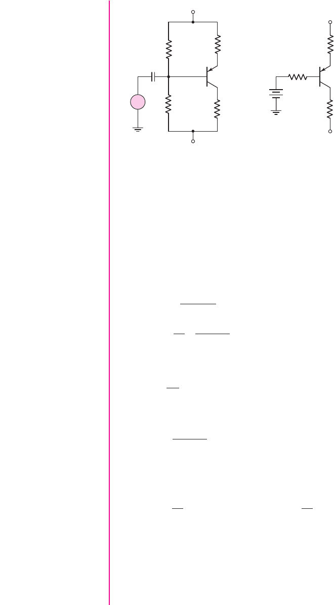
Objective: Design a bias-stable pnp transistor circuit to meet a set of specifications.
Specifications: The circuit configuration to be designed is shown in Figure 5.57(a).
The transistor Q-point values are to be:
V
ECQ
= 7
V,
I
CQ
∼
=
0.5
mA, and
V
RE
∼
=
1
V.
5.4.3
nea80644_ch05_285-368.qxd 06/12/2009 08:42 PM Page 339 F506 Tempwork:Dont' Del Rakesh:June:Rakesh 06-12-09:MHDQ134-05:
340 Part 1 Semiconductor Devices and Basic Applications
Choices: Assume transistor parameters of
β = 80
and
V
EB
(on) = 0.7
V. Standard
resistor values are to be used in the final design.
Solution: The Thevenin equivalent circuit is shown in Figure 5.57(b). The Thevenin
equivalent resistance is
R
TH
= R
1
R
2
and the Thevenin equivalent voltage, mea-
sured with respect to ground, is given by
V
TH
=
R
2
R
1
+ R
R
(V
+
− V
−
) + V
−
=
1
R
1
R
1
R
2
R
1
+ R
2
(V
+
− V
−
) + V
−
For
V
RE
∼
=
1
V and
I
CQ
∼
=
0.5
mA, then we can set
R
E
=
1
0.5
= 2k
For a bias stable circuit, we want
R
TH
=
R
1
R
2
R
1
+ R
2
= (0.1)(1 +β)R
E
= (0.1)(81)(2) = 16.2k
Then the Thevenin equivalent voltage can be written as
V
TH
=
1
R
1
(16.2)[9 − (−9)] + (−9) =
1
R
1
(291.6) − 9
The KVL equation around the E–B loop is given by
V
+
= I
EQ
R
E
+ V
EB
(on) + I
BQ
R
TH
+ V
TH
The transistor is to be biased in the forward-active mode so that
I
EQ
= (1 +β)I
BQ
.
We then have
V
+
= (1 +β)I
BQ
R
E
+ V
EB
(on) + I
BQ
R
TH
+ V
TH
v
s
R
1
R
E
C
C
R
C
R
2
V
–
= –9 V
+
–
V
+
= +9 V
+
–
V
RE
+
–
V
TH
R
TH
R
E
R
C
V
–
= –9 V
V
+
= +9 V
(a) (b)
Figure 5.57 (a) Circuit for Example 5.17 and (b) Thevenin equivalent circuit
nea80644_ch05_285-368.qxd 06/12/2009 08:42 PM Page 340 F506 Tempwork:Dont' Del Rakesh:June:Rakesh 06-12-09:MHDQ134-05:

Chapter 5 The Bipolar Junction Transistor 341
For
I
CQ
= 0.5
mA, then
I
BQ
= 0.00625
mA so we can write
9 = (81)(0.00625)(2) + 0.7 +(0.00625)(16.2) +
1
R
1
(291.6) − 9
We find
R
1
= 18.0
k
. Then, from
R
TH
= R
1
R
2
= 16.2
k
, we find
R
2
= 162
k
.
For
I
CQ
= 0.5
mA, then
I
EQ
= 0.506
mA. The KVL equation around the E–C
loop yields
V
+
= I
EQ
R
E
+ V
ECQ
+ I
CQ
R
C
+ V
−
or
9 = (0.506)(2) + 7 + (0.50)R
C
+(−9)
which yields
R
C
∼
=
20 k
Trade-offs: All resistor values are standard values except for
R
2
= 162
k
. A stan-
dard discrete value of 160 k
is available. However, because of the bias-stable de-
sign, the Q-point will not change significantly. The change in Q-point values with a
change in transistor current gain
β
is considered in end-of-chapter problems such as
Problems 5.31 and 5.34.
Comment: In many cases, specifications such as a collector current level or an
emitter–collector voltage value are not absolute, but are given as approximate values.
For this reason, the emitter resistor, for example, is determined to be 2 k
, which is
a standard discrete resistor value. The final bias resistor values are also chosen to be
standard values. However, these small changes compared to the calculated resistor
values will not change the Q-point values significantly.
EXERCISE PROBLEM
Ex 5.17: Consider the circuit shown in Figure 5.58. The transistor parameters are
β = 150
and
V
BE
(
on
)
= 0.7
V. The circuit parameters are
R
E
= 2
k
and
R
C
= 10
k
. Design a bias-stable circuit such that the quiescent output voltage is
zero. What are the values of
I
CQ
and
V
CEQ
? (Ans.
I
CQ
= 0.5
mA,
V
CEQ
= 3.99
V,
R
1
= 167
k
,
R
2
= 36.9
k
)
R
C
C
C
R
E
R
2
R
1
v
s
V
–
= –5 V
+
–
V
+
= +5 V
+
–
v
O
Figure 5.58 Figure for Exercise Ex 5.17
nea80644_ch05_285-368.qxd 06/12/2009 08:42 PM Page 341 F506 Tempwork:Dont' Del Rakesh:June:Rakesh 06-12-09:MHDQ134-05:
342 Part 1 Semiconductor Devices and Basic Applications
Integrated Circuit Biasing
The resistor biasing of transistor circuits considered up to this point is primarily
applied to discrete circuits. For integrated circuits, we would like to eliminate as
many resistors as possible since, in general, they require a larger surface area than
transistors.
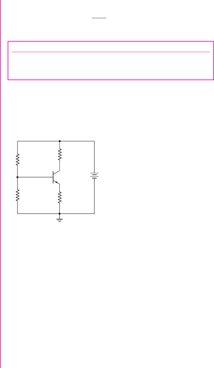
A bipolar transistor can be biased by using a constant-current source
I
Q
,as
shown in Figure 5.59. The advantages of this circuit are that the emitter current is
independent of
β
and
R
B
, and the collector current and C–E voltage are essentially
independent of transistor current gain, for reasonable values of
β
. The value of
R
B
can be increased, thus increasing the input resistance at the base, without jeopardiz-
ing the bias stability.
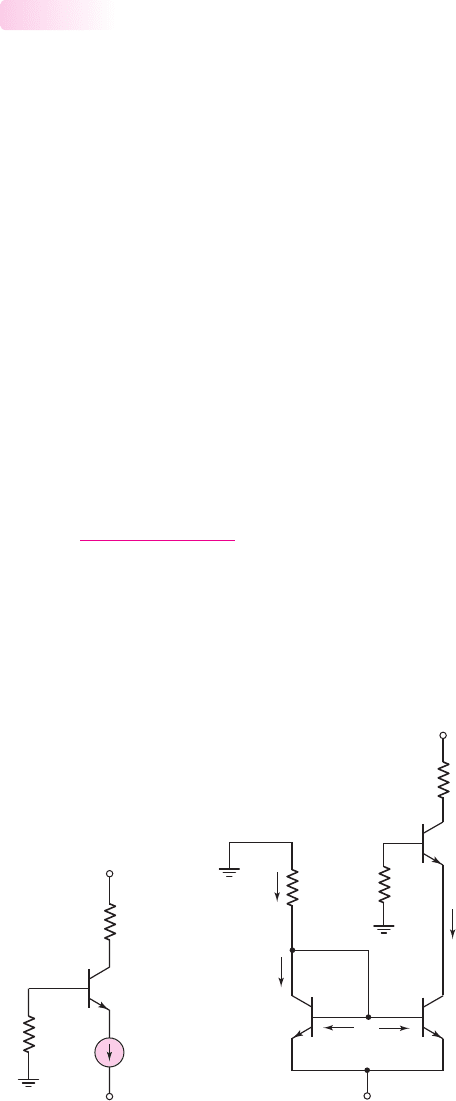
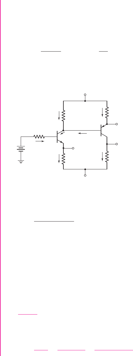
The constant current source can be implemented by using transistors as shown
in Figure 5.60. The transistor
Q
1
is a diode-connected transistor, but still operates in
the forward-active mode. The transistor
Q
2
must also operate in the forward-active
mode
(V
CE
≥ V
BE
(on)).
Current
I
1
is called the reference current and is found by writing Kirchhoff’s
voltage law equation around the
R
1
–
Q
1
loop. We have
0 = I
1
R
1
+ V
BE
(on) + V
−
(5.43(a))
which yields
I
1
=
−(V
−
+ V
BE
(on))
R
1
(5.43(b))
Since
V
BE1
= V
BE2
, the circuit mirrors the reference current in the left branch into
the right branch. The circuit of
R
1
,
Q
1
, and
Q
2
is then referred to as a current mirror.
Summing the currents at the collector of
Q
1
gives
I
1
= I
C1
+ I
B1
+ I
B2
(5.44)
5.4.4
R
B
R
C
I
Q
Q
O
V
–
V
+
Figure 5.59 Bipolar
transistor biased with a
constant-current source
R
C
R
1
R
B
V
+
= +5 V
V
–
= –5 V
I
B2
I
B1
I
C2
= I
Q
I
C1
I
1
Q
1
Q
O
Q
2
Figure 5.60 Transistor
Q
O
biased with a
constant current source. The transistors
Q
1
and
Q
2
form a current mirror.
nea80644_ch05_285-368.qxd 06/12/2009 08:42 PM Page 342 F506 Tempwork:Dont' Del Rakesh:June:Rakesh 06-12-09:MHDQ134-05:

Chapter 5 The Bipolar Junction Transistor 343
The B–E voltages of
Q
1
and
Q
2
are equal. If
Q
1
and
Q
2
are identical transistors and
are held at the same temperature, then
I
B1
= I
B2
and
I
C1
= I
C2
. Equation (5.44) can
then be written as
I
1
= I
C1
+2I
B2
= I
C2
+
2I
C2
β
= I
C2
1 +
2
β
(5.45)
Solving for
I
C2
, we find
I
C2
= I
Q
=
I
1
1 +
2
β
(5.46)
This current biases the transistor
Q
O
in the active region.
The circuit with
Q
1
,
Q
2
, and
R
1
is referred to as a two-transistor current source.
EXAMPLE 5.18
Objective: Determine the currents in a two-transistor current source.
For the circuit in Figure 5.60, the circuit and transistor parameters are:
R
1
=
10 k
,
β = 50
, and
V
BE
(on) = 0.7
V.
Solution: The reference current is
I
1
=
−(V
−
+ V
BE
(on))
R
1
=
−((−5) + 0.7)
10
= 0.43 mA
From Equation (5.46), the bias current
I
Q
is
I
C2
= I
Q
=
I
1
1 +
2
β
=
0.43
1 +
2
50
= 0.413 mA
The base currents are then
I
B1
= I
B2
=
I
C2
β
=
0.413
50
⇒ 8.27 μA
Comment: For relatively large values of current gain
β
, the bias current
I
Q
is essen-
tially the same as the reference current
I
1
.
EXERCISE PROBLEM
Ex 5.18: In the circuit shown in Figure 5.60, the parameters are
V
+
= 3.3
V,
V
−
=−3.3
V, and
R
B
= 0
. The transistor parameters are
β = 60
and
V
BE
(
on
)
=
0.7
V. Design the circuit such that
I
CQ
(
Q
O
)
= 0.12
mA and
V
CEQ
(
Q
O
)
= 1.6
V.
What are the values of
I
Q
and
I
1
? (Ans.
I
Q
= 0.122
mA,
I
1
= 0.126
mA,
R
1
= 20.6
k
,
R
C
= 20
k
)
As mentioned, constant-current biasing is used almost exclusively in integrated
circuits. As we will see in Part 2 of the text, circuits in integrated circuits use a min-
imum number of resistors, and transistors are often used to replace these resistors.
Transistors take up much less area than resistors on an IC chip, so it’s advantageous
to minimize the number of resistors.
nea80644_ch05_285-368.qxd 06/12/2009 08:42 PM Page 343 F506 Tempwork:Dont' Del Rakesh:June:Rakesh 06-12-09:MHDQ134-05:
344 Part 1 Semiconductor Devices and Basic Applications
Test Your Understanding
TYU 5.19 The parameters of the circuit shown in Figure 5.57(a) are
V
+
= 5
V,
V
−
=−5
V,
R
E
= 0.5
k
, and
R
C
= 4.5
k
. The transistor parameters are
β = 120
and
V
EB
(
on
)
= 0.7
V. Design a bias-stable circuit such that the
Q
-point is in the cen-
ter of the load line. What are the values of
I
CQ
and
V
ECQ
? (Ans.
I
CQ
= 1
mA,
V
ECQ
= 5
V,
R
1
= 6.92
k
,
R
2
= 48.1
k
)
TYU 5.20 For Figure 5.59, the circuit parameters are
I
Q
= 0.25
mA,
V
+
= 2.5
V,
V
−
=−2.5
V,
R
B
= 75
k
, and
R
C
= 4
k
. The transistor parameters are
I
S
= 3 ×10
−14
A and
β = 120
. (a) Determine the dc voltage at the base of the tran-
sistor and also
V
CEQ
. (b) Repeat part (a) for
β = 60
. (Ans. (a)
V
B
=−0.155
V,
V
CEQ
= 2.26V;
(b)
V
B
=−0.307
V,
V
CEQ
= 2.42
V)
5.5 MULTISTAGE CIRCUITS
Objective: • Consider the dc biasing of multistage or multitransistor
circuits.
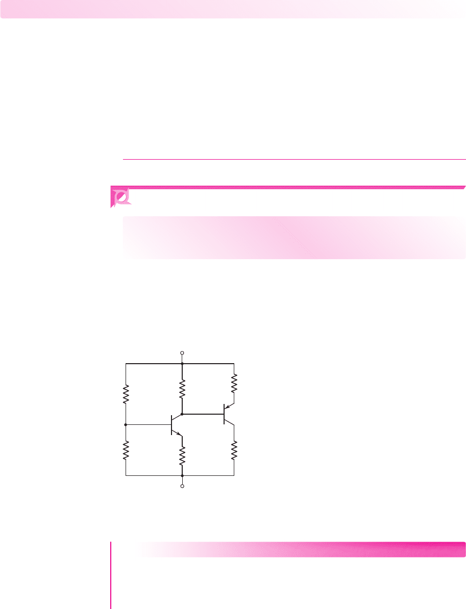
Most transistor circuits contain more than one transistor. We can analyze and design
these multistage circuits in much the same way as we studied single-transistor
circuits. As an example, Figure 5.61 shows an npn transistor,
Q
1
, and a pnp bipolar
transistor,
Q
2
, in the same circuit.
R
1
= 100 kΩ
R
C1
= 5 kΩ
R
E2
= 2 kΩ
R
C2
= 1.5 kΩ
R
E1
= 2 kΩ
–5 V
+5 V
R
2
= 50 kΩ
Q
1
Q
2
Figure 5.61 A multistage transistor circuit
EXAMPLE 5.19
Objective: Calculate the dc voltages at each node and the dc currents through the
elements in a multistage circuit.
For the circuit in Figure 5.61, assume the B–E turn-on voltage is 0.7 V and
β = 100
for each transistor.
nea80644_ch05_285-368.qxd 06/13/2009 05:06 PM Page 344 F506 Hard disk:Desktop Folder:Rakesh:MHDQ134-05:
Chapter 5 The Bipolar Junction Transistor 345
Solution:
The Thevenin equivalent circuit of the base circuit of
Q
1
is shown in
Figure 5.62. The various currents and nodal voltages are defined as shown. The
Thevenin resistance and voltage are
R
TH
= R
1
R
2
= 10050 = 33.3k
and
V
TH
=
R
2
R
1
+ R
2
(10) − 5 =
50
150
(10) − 5 =−1.67 V
Kirchhoff’s voltage law equation around the B–E loop of
Q
1
is
V
TH
= I
B1
R
TH
+ V
BE
(on) + I
E1
R
E1
−5
R
C1
= 5 kΩ
R
E2
= 2 kΩ
V
E2
V
C2
R
C2
= 1.5 kΩ
R
E1
= 2 kΩ
V
E1
–5 V
+5 V
Q
1
Q
2
+
–
V
TH
R
TH
= R
1
⎜⎜
R
2
I
E2
I
C2
I
E1
V
C1
I
R1
I
B2
I
B1
I
C1
Figure 5.62 Multistage transistor circuit with a Thevenin equivalent circuit in the base of
Q
1
Noting that
I
E1
= (1 +β)I
B1
, we have
I
B1
=
−1.67 + 5 −0.7
33.3 + (101)(2)
⇒ 11.2 μA
Therefore,
I
C1
= 1.12 mA
and
I
E1
= 1.13 mA
Summing the currents at the collector of
Q
1
, we obtain
I
R1
+ I
B2
= I
C1
which can be written as
5 − V
C1
R
C1
+ I
B2
= I
C1
(5.47)
The base current
I
B2
can be written in terms of the emitter current
I
E2
,as
follows:
I
B2
=
I
E2
1 + β
=
5 − V
E2
(1 + β)R
E2
=
5 − (V
C1
+0.7)
(1 + β)R
E2
(5.48)
nea80644_ch05_285-368.qxd 06/12/2009 08:42 PM Page 345 F506 Tempwork:Dont' Del Rakesh:June:Rakesh 06-12-09:MHDQ134-05:

346 Part 1 Semiconductor Devices and Basic Applications
Substituting Equation (5.48) into (5.47), we obtain
5 − V
C1
R
C1
+
5 − (V
C1
+0.7)
(1 + β)R
E2
= I
C1
= 1.12 mA
which can be solved for
V
C1
to yield
V
C1
=−0.482 V
Then,
I
R1
=
5 − (−0.482)
5
= 1.10 mA
To find
V
E2
, we have
V
E2
= V
C1
+ V
EB
(on) =−0.482 +0.7 = 0.218 V
The emitter current
I
E2
is
I
E2
=
5 − 0.218
2
= 2.39 mA
Then,
I
C2
=
β
1 + β
I
E2
=
100
101
(2.39) = 2.37 mA
and
I
B2
=
I
E2
1 + β
=
2.39
101
⇒ 23.7 μA
The remaining nodal voltages are
V
E1
= I
E1
R
E1
−5 = (1.13)(2) − 5 ⇒ V
E1
=−2.74 V
and
V
C2
= I
C2
R
C2
−5 = (2.37)(1.5) −5 =−1.45 V
We then find that
V
CE1
= V
C1
− V
E1
=−0.482 − (−2.74) = 2.26 V
and that
V
EC2
= V
E2
− V
C2
= 0.218 −(−1.45) = 1.67 V
Comment: These results show that both
Q
1
and
Q
2
are biased in the forward-active
mode, as originally assumed. However, when we consider the ac operation of this cir-
cuit as an amplifier in the next chapter, we will see that a better design would increase
the value of
V
EC2
.
EXERCISE PROBLEM
Ex 5.19: In the circuit shown in Figure 5.61, determine new values of
R
C1
and
R
C2
such that
V
CEQ1
= 3.25
V and
V
ECQ2
= 2.5
V. (Ans.
R
C1
= 4.08
k
,
R
C2
=
1.97
k
)
nea80644_ch05_285-368.qxd 06/12/2009 08:42 PM Page 346 F506 Tempwork:Dont' Del Rakesh:June:Rakesh 06-12-09:MHDQ134-05:
Chapter 5 The Bipolar Junction Transistor 347
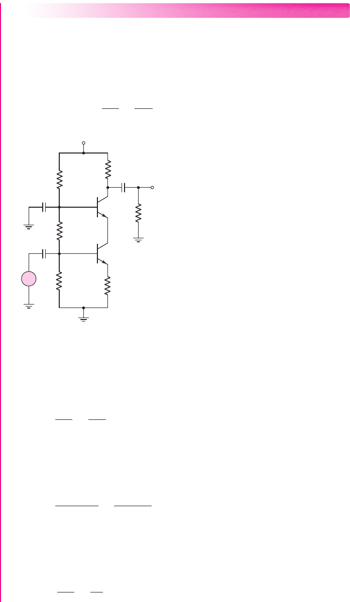
EXAMPLE 5.20
Objective: Design the circuit shown in Figure 5.63, called a cascode circuit, to meet
the following specifications:
V
CE1
= V
CE2
= 2.5
V,
V
RE
= 0.7
V,
I
C1
∼
=
I
C2
∼
=
1mA
, and
I
R1
∼
=
I
R2
∼
=
I
R3
∼
=
0.10 mA
.
Solution: The initial design will neglect base currents. We can then define
I
Bias
=
I
R1
= I
R2
= I
R3
= 0.10
mA. Then
R
1
+ R
2
+ R
3
=
V
+
I
Bias
=
9
0.10
= 90 k
v
i
v
o
R
1
R
2
Q
2
Q
1
R
E
C
C1
C
B
C
C2
R
C
R
3
+
–
V
+
= +9 V
+
–
V
RE
R
L
Figure 5.63 A bipolar cascode circuit for Example 5.20
The voltage at the base of
Q
1
is
V
B1
= V
RE
+ V
BE
(on) = 0.7 +0.7 = 1.4V
Then
R
3
=
V
B1
I
Bias
=
1.4
0.10
= 14 k
The voltage at the base of
Q
2
is
V
B2
= V
RE
+ V
CE1
+ V
BE
(on) = 0.7 +2.5 +0.7 = 3.9V
Then
R
2
=
V
B2
− V
B1
I
Bias
=
3.9 − 1.4
0.10
= 25 k
We then obtain
R
1
= 90 −25 −14 = 51 k
The emitter resistor
R
E
can be found as
R
E
=
V
RE
I
C1
=
0.7
1
= 0.7k
nea80644_ch05_285-368.qxd 06/12/2009 08:42 PM Page 347 F506 Tempwork:Dont' Del Rakesh:June:Rakesh 06-12-09:MHDQ134-05: