Neamen D. Microelectronics: Circuit Analysis and Design
Подождите немного. Документ загружается.

nea80644_ch05_285-368.qxd 06/12/2009 08:43 PM Page 368 F506 Tempwork:Dont' Del Rakesh:June:Rakesh 06-12-09:MHDQ134-05:

Chapter
In the previous chapter, we described the structure and operation of the bipolar junc-
tion transistor, and analyzed and designed the dc response of circuits containing these
devices. In this chapter, we emphasize the use of the bipolar transistor in linear am-
plifier applications. Linear amplifiers imply that, for the most part, we are dealing
with analog signals. The magnitude of an analog signal may have any value, within
limits, and may vary continuously with respect to time. A linear amplifier then means
that the output signal is equal to the input signal multiplied by a constant, where the
magnitude of the constant of proportionality is, in general, greater than unity.
PREVIEW
In this chapter, we will:
• Investigate the process by which a transistor circuit can amplify a small, time-
varying input signal, and develop the small-signal models of the transistor
that are used in the analysis of linear amplifiers.
• Discuss the three basic transistor amplifier configurations.
• Analyze the common-emitter amplifier and become familiar with the general
characteristics of this circuit.
• Understand the concept of the ac load line and determine the maximum sym-
metrical swing of the output signal.
• Analyze the emitter-follower amplifier and become familiar with the general
characteristics of this circuit.
• Analyze the common-base amplifier and become familiar with the general
characteristics of this circuit.
• Compare the general characteristics of the three basic amplifier configurations.
• Analyze multitransistor or multistage amplifiers and understand the advan-
tages of these circuits over single-transistor circuits.
• Understand the concept of signal power gain in an amplifier circuit.
• As an application, incorporate bipolar transistors in a design of a multistage
amplifier circuit configuration to provide a specified output signal power.
Basic BJT Amplifiers
6
6
369
nea80644_ch06_369-468.qxd 06/13/2009 07:32 PM Page 369 F506 Hard disk:Desktop Folder:Rakesh:MHDQ134-06:

370 Part 1 Semiconductor Devices and Basic Applications
6.1 ANALOG SIGNALS AND LINEAR AMPLIFIERS
Objective: • Understand the concept of an analog signal and the
principle of a linear amplifier.
In this chapter, we will be considering signals, analog circuits, and amplifiers. A
signal contains some type of information. For example, sound waves produced by
a speaking human contain the information the person is conveying to another
person. A sound wave is an analog signal. The magnitude of an analog signal can
take on any value, within limits, and may vary continuously with time. Electronic
circuits that process analog signals are called analog circuits. One example of an
analog circuit is a linear amplifier. A linear amplifier magnifies an input signal and
produces an output signal whose magnitude is larger and directly proportional to the
input signal.
Time-varying signals from a particular source very often need to be amplified
before the signal is capable of being “useful.” For example, Figure 6.1 shows a sig-
nal source that may be the output of a microphone. The output of the microphone will
need to be amplified in order to drive the speakers at the output. The amplifier is the
circuit that performs this function. A dc voltage source is also an input to the ampli-
fier. The amplifier contains transistors that must be biased so that the transistors can
act as amplifying devices.
In this chapter, we analyze and design linear amplifiers that use bipolar transis-
tors as the amplifying device. The term small-signal means that we can linearize the
ac equivalent circuit. We will define what is meant by small signal in the case of BJT
circuits. The term linear amplifier means that we can use superposition so that the dc
analysis and ac analysis of the circuits can be performed separately and the total re-
sponse is the sum of the two individual responses.
The mechanism by which BJT circuits amplify small time-varying signals was
introduced in the last chapter. In this section, we will expand that discussion, using
the graphical technique, dc load line, and ac load line. In the process, we will develop
the various small-signal parameters of linear circuits and the corresponding equiva-
lent circuits.
Figure 6.1 suggests that there are two types of analyses of the amplifier that we
must consider. The first is a dc analysis because of the applied dc voltage source, and
the second is a time-varying or ac analysis because of the time-varying signal source.
dc power
supply input
Signal
output
Signal
input
Ground or
Electronic
circuit
v
O
V
DC
v
I
Figure 6.1 Schematic of an electronic circuit with two input signals: the dc power supply
input, and the signal input
nea80644_ch06_369-468.qxd 06/13/2009 07:32 PM Page 370 F506 Hard disk:Desktop Folder:Rakesh:MHDQ134-06:
Chapter 6 Basic BJT Amplifiers 371
A linear amplifier means that the superposition principle applies. The principle of
superposition states: The response of a linear circuit excited by multiple independent
input signals is the sum of the responses of the circuit to each of the input signals
alone.
For the linear amplifier, then, the dc analysis can be performed with the ac
source set to zero. This analysis, called a large signal analysis, establishes the
Q-point of the transistors in the amplifier. This analysis and design was the primary
objective of the previous chapter. The ac analysis, called a small-signal analysis, can
be performed with the dc source set to zero. The total response of the amplifier cir-
cuit is the sum of the two individual responses.
6.2 THE BIPOLAR LINEAR AMPLIFIER
Objective: • Investigate the process by which a single-transistor cir-
cuit can amplify a small, time-varying input signal and develop the
small-signal models of the transistor that are used in the analysis of
linear amplifiers.
The transistor is the heart of an amplifier. In this chapter, we will consider bipolar
transistor amplifiers. Bipolar transistors have traditionally been used in linear ampli-
fier circuits because of their relatively high gain.
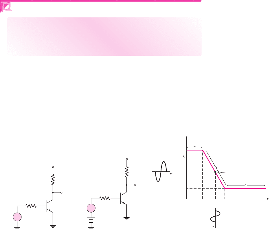
We begin our discussion by considering the same bipolar circuit that was dis-
cussed in the last chapter. Figure 6.2(a) shows the circuit where the input signal
v
I
contains both a dc and an ac signal. Figure 6.2(b) shows the same circuit where
V
BB
is a dc voltage to bias the transistor at a particular Q-point and
v
s
is the ac signal that
is to be amplified. Figure 6.2(c) shows the voltage transfer characteristics that were
+
–
v
I
R
B
v
O
R
C
V
CC
Q
+
–
v
s
V
BB
+
–
R
B
v
O
R
C
V
CC
V
CE
(sat)
V
BB
t
Q cutoff
Q in saturation
Q-point
Q in forward-active region
V
CEQ
t
V
CC
v
O
v
I
(a) (b) (c)
Figure 6.2 (a) Bipolar transistor inverter circuit, (b) inverter circuit showing both dc bias and
ac signal sources in the base circuit, and (c) transistor inverter voltage transfer characteristics
showing desired Q-point
nea80644_ch06_369-468.qxd 06/13/2009 07:32 PM Page 371 F506 Hard disk:Desktop Folder:Rakesh:MHDQ134-06:

372 Part 1 Semiconductor Devices and Basic Applications
Table 6.1 Summary of notation
Variable Meaning
i
B
,
v
BE
Total instantaneous values
I
B
,
V
BE
DC values
i
b
,
v
be
Instantaneous ac values
I
b
,
V
be
Phasor values
developed in Chapter 5. To use the circuit as an amplifier, the transistor needs to be
biased with a dc voltage at a quiescent point (Q-point), as shown in the figure, such
that the transistor is biased in the forward-active region. This dc analysis or design of
the circuit was the focus of our attention in Chapter 5. If a time-varying (e.g., sinu-
soidal) signal is superimposed on the dc input voltage,
V
BB
, the output voltage will
change along the transfer curve producing a time-varying output voltage. If the time-
varying output voltage is directly proportional to and larger than the time-varying
input voltage, then the circuit is a linear amplifier. From this figure, we see that if the
transistor is not biased in the active region (biased either in cutoff or saturation), the
output voltage does not change with a change in the input voltage. Thus, we no
longer have an amplifier.
In this chapter, we are interested in the ac analysis and design of bipolar transis-
tor amplifiers, which means that we must determine the relationships between the
time-varying output and input signals. We will initially consider a graphical tech-
nique that can provide an intuitive insight into the basic operation of the circuit. We
will then develop a small-signal equivalent circuit that will be used in the mathe-
matical analysis of the ac signals. In general, we will be considering a steady-state,
sinusoidal analysis of circuits. We will assume that any time-varying signal can be
written as a sum of sinusoidal signals of different frequencies and amplitudes
(Fourier series), so that a sinusoidal analysis is appropriate.
We will be dealing with time-varying as well as dc currents and voltages in this
chapter. Table 6.1 gives a summary of notation that will be used. This notation was
discussed in the Prologue, but is repeated here for convenience. A lowercase letter
with an uppercase subscript, such as
i
B
or
v
BE
, indicates total instantaneous values.
An uppercase letter with an uppercase subscript, such as
I
B
or
V
BE
, indicates dc
quantities. A lowercase letter with a lowercase subscript, such as
i
b
or
v
be
, indicates
instantaneous values of ac signals. Finally, an uppercase letter with a lowercase
subscript, such as
I
b
or
V
be
, indicates phasor quantities. The phasor notation, which
was reviewed in the Prologue becomes especially important in Chapter 7 during the
discussion of frequency response. However, the phasor notation will be generally
used in this chapter in order to be consistent with the overall ac analysis.
Graphical Analysis and ac Equivalent Circuit
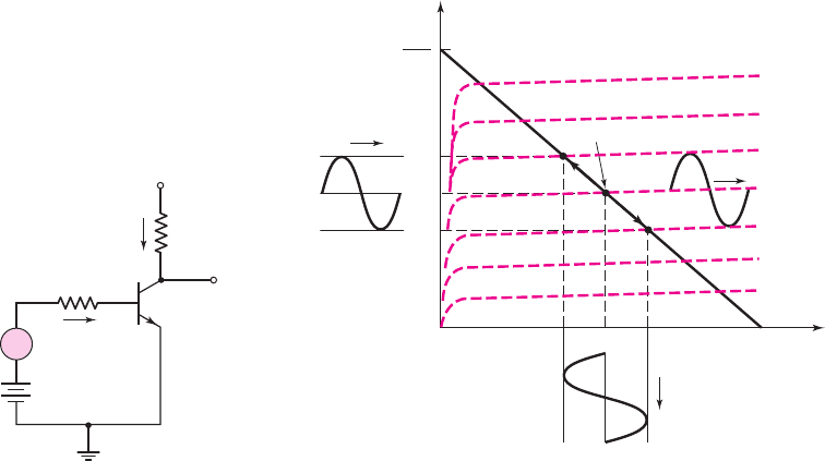
Figure 6.3 shows the same basic bipolar inverter circuit that has been discussed, but
now includes a sinusoidal signal source in series with the dc source as was shown in
Figure 6.2(b).
6.2.1
nea80644_ch06_369-468.qxd 06/13/2009 07:32 PM Page 372 F506 Hard disk:Desktop Folder:Rakesh:MHDQ134-06:
Chapter 6 Basic BJT Amplifiers 373
+
+
–
–
V
BB
–
v
BE
V
CC
R
C
i
B
R
B
i
C
+
v
CE
v
s
v
O
+
–
Figure 6.3 A common-emitter circuit
with a time-varying signal source in
series with the base dc source
v
C
E
I
CQ
I
BQ
i
C
i
+
B
v
CE
v
CE
i
B
V
CC
V
CEQ
Time
Time
Q-point
Time
i
C
V
CC
R
C
i
C
–
–
–
+
+
Figure 6.4 Common-emitter transistor characteristics, dc load
line, and sinusoidal variation in base current, collector current,
and collector–emitter voltage
Figure 6.4 shows the transistor characteristics, the dc load line, and the Q-point.
The sinusoidal signal source,
v
s
, will produce a time-varying or ac base current
superimposed on the quiescent base current as shown in the figure. The time-varying
base current will induce an ac collector current superimposed on the quiescent col-
lector current. The ac collector current then produces a time-varying voltage across
R
C
, which induces an ac collector–emitter voltage as shown in the figure. The ac
collector–emitter voltage, or output voltage, in general, will be larger than the sinu-
soidal input signal, so that the circuit has produced signal amplification—that is, the
circuit is an amplifier.
We need to develop a mathematical method or model for determining the
relationships between the sinusoidal variations in currents and voltages in the cir-
cuit. As already mentioned, a linear amplifier implies that superposition applies so
that the dc and ac analyses can be performed separately. To obtain a linear ampli-
fier, the time-varying or ac currents and voltages must be small enough to ensure
a linear relation between the ac signals. To meet this objective, the time-varying
signals are assumed to be small signals, which means that the amplitudes of the ac
signals are small enough to yield linear relations. The concept of “small enough,”
or small signal, will be discussed further as we develop the small-signal equivalent
circuits.
A time-varying signal source,
v
s
, in the base of the circuit in Figure 6.3 gener-
ates a time-varying component of base current, which implies there is also a time-
varying component of base–emitter voltage. Figure 6.5 shows the exponential
relationship between base-current and base–emitter voltage. If the magnitudes of
the time-varying signals that are superimposed on the dc quiescent point are small,
then we can develop a linear relationship between the ac base–emitter voltage
and ac base current. This relationship corresponds to the slope of the curve at the
Q-point.
nea80644_ch06_369-468.qxd 06/13/2009 07:32 PM Page 373 F506 Hard disk:Desktop Folder:Rakesh:MHDQ134-06:

374 Part 1 Semiconductor Devices and Basic Applications
r
p
i
B
I
BQ
v
B
E
V
BEQ
Slope =
Time
Time
1
Figure 6.5 Base current versus base–emitter voltage characteristic with superimposed
sinusoidal signals. Slope at the Q-point is inversely proportional to r
π
, a small-signal parameter.
Small Signal
Using Figure 6.5, we can now determine one quantitative definition of small signal.
From the discussion in Chapter 5, in particular, Equation (5.6), the relation between
base–emitter voltage and base current can be written as
i
B
=
I
S
β
· exp
v
BE
V
T
(6.1)
If
v
BE
is composed of a dc term with a sinusoidal component superimposed, i.e.,
v
BE
= V
BEQ
+v
be
, then
i
B
=
I
S
β
· exp
V
BEQ
+v
be
V
T
=
I
S
β
· exp
V
BEQ
V
T
· exp
v
be
V
T
(6.2)
where
V
BEQ
is normally referred to as the base–emitter turn-on voltage,
V
BE
(on).
The term
[I
S
/β] · exp(V
BEQ
/V
T
)
is the quiescent base current, so we can write
i
B
= I
BQ
· exp
v
be
V
T
(6.3)
The base current, given in this form, is not linear and cannot be written as an ac
current superimposed on a dc quiescent value. However, if
v
be
V
T
, then we can
expand the exponential term in a Taylor series, keeping only the linear term. This
approximation is what is meant by small signal. We then have
i
B
∼
=
I
BQ
1 +
v
be
V
T
= I
BQ
+
I
BQ
V
T
· v
be
= I
BQ
+i
b
(6.4(a))
nea80644_ch06_369-468.qxd 06/13/2009 07:32 PM Page 374 F506 Hard disk:Desktop Folder:Rakesh:MHDQ134-06:

Chapter 6 Basic BJT Amplifiers 375
where
i
b
is the time-varying (sinusoidal) base current given by
i
b
=
I
BQ
V
T
v
be
(6.4(b))
The sinusoidal base current,
i
b
, is linearly related to the sinusoidal base–emitter volt-
age,
v
be
. In this case, the term small-signal refers to the condition in which
v
be
is
sufficiently small for the linear relationships between
i
b
and
v
be
given by Equa-
tion (6.4(b)) to be valid. As a general rule, if
v
be
is less than l0 mV, then the expo-
nential relation given by Equation (6.3) and its linear expansion in Equation (6.4(a))
agree within approximately 10 percent. Ensuring that
v
be
< 10
mV is another useful
rule of thumb in the design of linear bipolar transistor amplifiers.
If the
v
be
signal is assumed to be sinusoidal, but if its magnitude becomes
too large, then the output signal will no longer be a pure sinusoidal voltage but will
become distorted and contain harmonics (see box “Harmonic Distortion”).
Harmonic Distortion
If an input sinusoidal signal becomes too large, the output signal may no longer
be a pure sinusoidal signal because of nonlinear effects. A nonsinusoidal output
signal may be expanded into a Fourier series and written in the form
v
O
(t) = V
O
+ V
1
sin(ωt + φ
1
) + V
2
sin(2ωt + φ
2
) + V
3
sin(3ωt + φ
3
) +···
dc desired 2nd harmonic 3rd harmonic
linear output distortion distortion
(6.5)
The signal at the frequency
ω
is the desired linear output signal for a sinusoidal
input signal at the same frequency.
The time-varying input base-emitter voltage is contained in the exponential
term given in Equation (6.3). Expanding the exponential function into a Taylor
series, we find
e
x
= 1 + x +
x
2
2
+
x
3
6
+···
(6.6)
where, from Equation (6.3), we have
x = v
be
/V
T
. If we assume the input signal is
a sinusoidal function, then we can write
x =
v
be
V
T
=
V
π
V
T
sin ωt
(6.7)
The exponential function can then be written as
e
x
= 1 +
V
π
V
T
sin ωt +
1
2
·
V
π
V
T
2
sin
2
ωt +
1
6
·
V
π
V
T
3
sin
3
ωt +···
(6.8)
From trigonometric identities, we can write
sin
2
ωt =
1
2
[1 − cos(2ωt)] =
1
2
[1 − sin(2ωt +90
◦
)]
(6.9a)
and
sin
3
ωt =
1
4
[3 sin ωt −sin(3ωt)]
(6.9b)
nea80644_ch06_369-468.qxd 06/13/2009 07:32 PM Page 375 F506 Hard disk:Desktop Folder:Rakesh:MHDQ134-06:

376 Part 1 Semiconductor Devices and Basic Applications
Substituting Equations (6.9a) and (6.9b) into Equation (6.8), we obtain
e
x
=
1 +
1
4
V
π
V
T
2
+
V
π
V
T
1 +
1
8
V
π
V
T
2
sin ωt
−
1
4
V
π
V
T
2
sin(2ωt + 90
◦
) −
1
24
V
π
V
T
3
sin(3ωt) +···
(6.10)
Comparing Equation (6.10) to Equation (6.8), we find the coefficients as
V
O
=
1 +
1
4
V
π
V
T
2
V
1
=
V
π
V
T
1 +
1
8
V
π
V
T
2
V
2
=−
1
4
V
π
V
T
2
V
3
=−
1
24
V
π
V
T
3
(6.11)
We see that as
(V
π
/V
T
)
increases, the second and third harmonic terms become
non-zero. In addition, the dc and first harmonic coefficients also become nonlin-
ear. A figure of merit is called the percent total harmonic distortion (THD) and is
defined as
THD(%) =
∞
2
V
2
n
V
1
×100%
(6.12)
Considering only the second and third harmonic terms, the THD is plotted in
Figure 6.6. We see that, for
V
π
≤ 10
mV, the THD is less than 10 percent. This
total harmonic distortion value may seem excessive, but as we will see later in
Chapter 12, distortion can be reduced when feedback circuits are used.
THD (%)
V
p
(mV)
5
0 5 10 15 20
10
15
20
Figure 6.6 Total harmonic distortion of the function
e
v
BE
/V
T
, where
v
BE
= V
π
sin ωt
,as
a function of
V
π
nea80644_ch06_369-468.qxd 06/13/2009 07:32 PM Page 376 F506 Hard disk:Desktop Folder:Rakesh:MHDQ134-06:
Chapter 6 Basic BJT Amplifiers 377
The AC Equivalent Circuit
From the concept of small signal, all the time-varying signals shown in Figure 6.4
will be linearly related and are superimposed on dc values. We can write (refer to no-
tation given in Table 6.1)
i
B
= I
BQ
+i
b
(6.13(a))
i
C
= I
CQ
+i
c
(6.13(b))
v
CE
= V
CEQ
+v
ce
(6.13(c))
and
v
BE
= V
BEQ
+v
be
(6.13(d))
The Base–Emitter Loop: If the signal source,
v
s
, is zero, then the base-emitter loop
equation is
V
BB
= I
BQ
R
B
+ V
BEQ
(6.14)
Taking into account the time-varying signals, we find the base–emitter loop
equation is
V
BB
+v
s
= i
B
R
B
+v
BE
(6.15(a))
or
V
BB
+v
s
= (I
BQ
+i
b
)R
B
+(V
BEQ
+v
be
)
(6.15(b))
Rearranging terms, we find
V
BB
− I
BQ
R
B
− V
BEQ
= i
b
R
B
+v
be
−v
s
(6.15(c))
From Equation (6.14), we see that the left side of Equation (6.15(c)) is zero. Equa-
tion (6.15(c)) can then be written as
v
s
= i
b
R
B
+v
be
(6.16)
which is the base-emitter loop equation with all dc term effectively set equal to zero.
The Collector–Emitter Loop: Again, if the signal source,
v
s
, is zero, then the collec-
tor-emitter loop equation is
V
CC
= I
CQ
R
C
+ V
CEQ
(6.17)
Taking into account the time-varying signals, the collector-emitter loop equation be-
comes
V
CC
= i
C
R
C
+v
CE
= (I
CQ
+i
c
)R
C
+(V
CEQ
+v
ce
)
(6.18(a))
Rearranging terms, we find
V
CC
− I
CQ
R
C
− V
CEQ
= i
c
R
C
+v
ce
(6.18(b))
From Equation (6.17), we see that the left side of Equation (6.18(b)) is zero. Equa-
tion (6.18(b)) can be written as
i
c
R
C
+v
ce
= 0
(6.19)
which is the collector–emitter loop equation with all dc terms set equal to zero.
Equations (6.16) and (6.19) relate the ac parameters in the circuit. These equa-
tions can be obtained directly by setting all dc currents and voltages equal to zero, so
the dc voltage sources become short circuits and any dc current sources would
nea80644_ch06_369-468.qxd 06/13/2009 07:32 PM Page 377 F506 Hard disk:Desktop Folder:Rakesh:MHDQ134-06: