Neamen D. Microelectronics: Circuit Analysis and Design
Подождите немного. Документ загружается.

398 Part 1 Semiconductor Devices and Basic Applications
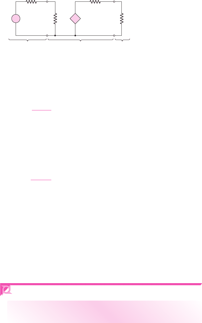
If we wish to design a voltage amplifier (preamp) so that the output voltage of a
microphone, for example, is amplified, the total equivalent circuit may be that shown
in Figure 6.25. The input voltage to the amplifier is given by
v
in
=
R
i
R
i
+ R
S
· v
s
(6.46)
In general, we would like the input voltage
v
in
to the amplifier to be as nearly equal
to the source voltage
v
s
as possible. This means, from Equation (6.46), that we need to
design the amplifier such that the input resistance
R
i
is much larger than the signal
source output resistance
R
S
. (The output resistance of an ideal voltage source is zero,
but is not zero for most practical voltage sources.) To provide a particular voltage gain,
the amplifier must have a gain parameter
A
vo
of a certain value. The output voltage sup-
plied to the load (where the load may be a second power amplifier stage) is given by
v
o
=
R
L
R
L
+ R
o
· A
vo
v
in
(6.47)
Normally, we would like the output voltage to the load to be equal to the
Thevenin equivalent voltage generated by the amplifier. This means that we need
R
o
R
L
for the voltage amplifier. So again, for a voltage amplifier, the output re-
sistance should be very small. The input and output resistances are significant in the
design of an amplifier.
For a current amplifier, we would like to have
R
i
R
S
and
R
o
R
L
. We will
see as we proceed through the chapter that each of the three basic transistor amplifier
configurations exhibits characteristics that are desirable for particular applications.
We should note that, in this chapter, we will be primarily using the two-port
equivalent circuits shown in Table 6.3 to model single-transistor amplifiers. How-
ever, these equivalent circuits are also used to model multitransistor circuits. This
will become apparent as we get into Part 2 of the text.
6.4 COMMON-EMITTER AMPLIFIERS
Objective: • Analyze the common-emitter amplifier and become
familiar with the general characteristics of this circuit.
In this section, we consider the first of the three basic amplifiers—the common-
emitter circuit. We will apply the equivalent circuit of the bipolar transistor that was
previously developed. In general, we will use the hybrid-
π
model throughout the text.
+
–
+
–
v
in
v
s
R
o
R
S
R
i
R
L
+
–
Equivalent
circuit of
microphone
Equivalent
amplifier
circuit
Equivalent
load circui
t
v
o
+
–
A
vo
v
in
Figure 6.25 Equivalent preamplifier circuit
nea80644_ch06_369-468.qxd 06/13/2009 07:32 PM Page 398 F506 Hard disk:Desktop Folder:Rakesh:MHDQ134-06:
Chapter 6 Basic BJT Amplifiers 399
If the signal source is a sinusoidal voltage at frequency f, then the magnitude of
the capacitor impedance is
|
Z
c
|
= [1/(2π fC
C
)]
. For example, assume that
C
C
=
10 μF
and
f = 2
kHz. The magnitude of the capacitor impedance is then
|
Z
c
|
=
1
2π fC
C
=
1
2π(2 ×10
3
)(10 × 10
−6
)
∼
=
8
(6.48)
The magnitude of this impedance is in general much less than the Thevenin resis-
tance at the capacitor terminals, which in this case is
R
1
R
2
r
π
. We can therefore as-
sume that the capacitor is essentially a short circuit to signals with frequencies
greater than 2 kHz. We are also neglecting any capacitance effects within the transis-
tor. Using these results, our analyses in this chapter assume that the signal frequency
is sufficiently high that any coupling capacitance acts as a perfect short circuit, and is
also sufficiently low that the transistor capacitances can be neglected. Such frequen-
cies are in the midfrequency range, or simply at the midband of the amplifier.
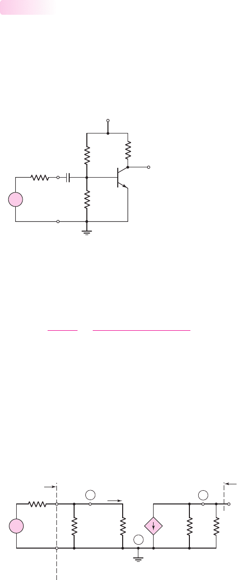
The small-signal equivalent circuit in which the coupling capacitor is assumed
to be a short circuit is shown in Figure 6.27. The small-signal variables, such as the
R
2
R
1
R
S
R
C
v
s
v
O
V
CC
C
C
+
–
+
–
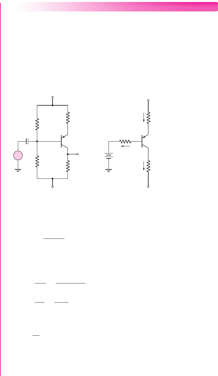
Figure 6.26 A common-emitter circuit with a voltage-divider biasing circuit and a coupling
capacitor
+
–
V
p
r
p
V
o
r
o
R
o
g
m
V
p
R
C
I
b
R
1
⎜⎜ R
2
R
S
V
s
C
B
E
R
i
Signal
source
Amplifier
+
–
Figure 6.27 The small-signal equivalent circuit, assuming the coupling capacitor is a short circuit
Basic Common-Emitter Amplifier Circuit
Figure 6.26 shows the basic common-emitter circuit with voltage-divider biasing. We
see that the emitter is at ground potential—hence the name common emitter. The sig-
nal from the signal source is coupled into the base of the transistor through the cou-
pling capacitor
C
C
, which provides dc isolation between the amplifier and the signal
source. The dc transistor biasing is established by
R
1
and
R
2
, and is not disturbed
when the signal source is capacitively coupled to the amplifier.
6.4.1
nea80644_ch06_369-468.qxd 06/13/2009 07:32 PM Page 399 F506 Hard disk:Desktop Folder:Rakesh:MHDQ134-06:
400 Part 1 Semiconductor Devices and Basic Applications
input signal voltage and input base current, are given in phasor form. The control
voltage
V
π
is also given as a phasor.
The output voltage is
V
o
=−g
m
V
π
(
r
o
R
C
)
(6.49)
and the control voltage
V
π
is found to be
V
π
=
R
1
R
2
r
π
R
1
R
2
r
π
+ R
S
· V
s
(6.50)
Combining Equations (6.49) and (6.50), we see that the small-signal voltage gain is
A
v
=
V
o
V
s
=−g
m
(r
o
R
C
)
R
1
R
2
r
π
R
1
R
2
r
π
+ R
S
(6.51)
The circuit in Figure 6.26 is not very practical. The voltage across
R
2
provides the
base–emitter voltage to bias the transistor in the forward-active region. However, a
slight variation in the resistor value or a slight variation in the transistor characteristics
may cause the transistor to be biased in cutoff or saturation. The next section discusses
an improved circuit configuration.
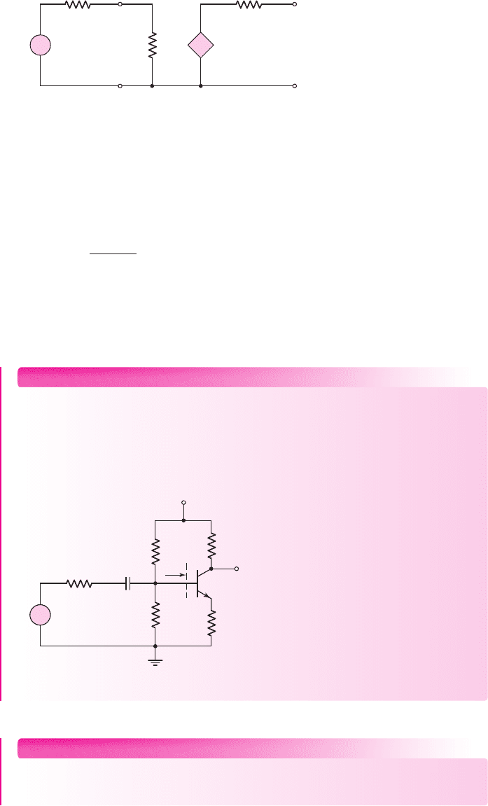
Circuit with Emitter Resistor
In the last chapter, we found that the Q-point was stabilized against variations in
β
if an
emitter resistor were included in the circuit, as shown in Figure 6.28. We will find a
similar property for the ac signals, in that the voltage gain of a circuit with
R
E
will be
less dependent on the transistor current gain
β
. Even though the emitter of this circuit
is not at ground potential, this circuit is still referred to as a common-emitter circuit.
Assuming that
C
C
acts as a short circuit, Figure 6.29 shows the small-signal
hybrid-
π
equivalent circuit. As we have mentioned previously, to develop the
small-signal equivalent circuit, start with the three terminals of the transistor.
Sketch the hybrid-
π
equivalent circuit between the three terminals and then sketch
6.4.2
R
2
=
12.2 kΩ
R
1
=
56 kΩ
R
S
= 0.5 kΩ
R
C
= 2 kΩ
R
E
= 0.4 kΩ
v
s
v
O
V
CC
= 10 V
C
C
+
–
Figure 6.28 An npn common-emitter circuit with
an emitter resistor, a voltage-divider biasing
circuit, and a coupling capacitor
+
+
–
–
V
p
r
p
V
s
V
in
V
o
R
o
R
ib
R
i
R
1
⎜⎜ R
2
= 10.0 kΩ
I
b
R
E
= 0.4 kΩ
R
S
= 0.5 kΩ
R
C
= 2 kΩ
+
–
bI
b
Figure 6.29 The small-signal equivalent circuit of the circuit
shown in Figure 6.28
nea80644_ch06_369-468.qxd 06/13/2009 07:32 PM Page 400 F506 Hard disk:Desktop Folder:Rakesh:MHDQ134-06:

Chapter 6 Basic BJT Amplifiers 401
in the remaining circuit elements around these three terminals. In this case, we are
using the equivalent circuit with the current gain parameter
β
, and we are assum-
ing that the Early voltage is infinite so the transistor output resistance
r
o
can be ne-
glected (an open circuit). The ac output voltage is
V
o
=−(β I
b
)R
C
(6.52)
To find the small-signal voltage gain, it is worthwhile finding the input resis-
tance first. The resistance
R
ib
is the input resistance looking into the base of the tran-
sistor. We can write the following loop equation
V
in
= I
b
r
π
+(I
b
+β I
b
)R
E
(6.53)
The input resistance
R
ib
is then defined as, and found to be,
R
ib
=
V
in
I
b
= r
π
+(1 +β)R
E
(6.54)
In the common-emitter configuration that includes an emitter resistance, the
small-signal input resistance looking into the base of the transistor is
r
π
plus the
emitter resistance multiplied by the factor
(1 + β)
. This effect is called the resis-
tance reflection rule. We will use this result throughout the text without further
derivation.
The input resistance to the amplifier is now
R
i
= R
1
R
2
R
ib
(6.55)
We can again relate
V
in
to
V
s
through a voltage-divider equation as
V
in
=
R
i
R
i
+ R
S
· V
s
(6.56)
Combining Equations (6.52), (6.54), and (6.56), we find the small-signal voltage
gain is
A
v
=
V
o
V
s
=
−(β I
b
)R
C
V
s
=−β R
C
V
in
R
ib
·
1
V
s
(6.57)
or
A
v
=
−β R
C
r
π
+(1 +β)R
E
R
i
R
i
+ R
S
(6.58)
From this equation, we see that if
R
i
R
S
and if
(1 + β)R
E
r
π
, then the small-
signal voltage gain is approximately
A
v
∼
=
−β R
C
(1 + β)R
E
∼
=
−R
C
R
E
(6.59)
Equations (6.58) and (6.59) show that the voltage gain for this circuit is less de-
pendent on the current gain
β
than in the previous circuit (Equation (6.51), which
means that there is a smaller change in voltage gain when the transistor current gain
changes. The circuit designer now has more control in the design of the voltage gain,
but this advantage is at the expense of a smaller gain.
In Chapter 5, we discussed the variation in the Q-point with variations or toler-
ances in resistor values. Since the voltage gain is a function of resistor values, it is
also a function of the tolerances in those values. This must be considered in a circuit
design.
nea80644_ch06_369-468.qxd 06/13/2009 07:32 PM Page 401 F506 Hard disk:Desktop Folder:Rakesh:MHDQ134-06:

402 Part 1 Semiconductor Devices and Basic Applications
EXAMPLE 6.5
Objective: Determine the small-signal voltage gain and input resistance of a
common-emitter circuit with an emitter resistor.
For the circuit in Figure 6.28, the transistor parameters are:
β = 100
,
V
BE
(on) = 0.7
V, and
V
A
=∞
.
DC Solution: From a dc analysis of the circuit, we can determine that
I
CQ
=
2.16 mA and
V
CEQ
= 4.81
V, which shows that the transistor is biased in the
forward-active mode.
AC Solution: The small-signal hybrid-
π
parameters are determined to be
r
π
=
V
T
β
I
CQ
=
(0.026)(100)
(2.16)
= 1.20 k
g
m
=
I
CQ
V
T
=
2.16
0.026
= 83.1mA/V
and
r
o
=
V
A
I
CQ
=∞
The input resistance to the base can be determined as
R
ib
= r
π
+(1 +β)R
E
= 1.20 +(101)(0.4) = 41.6k
and the input resistance to the amplifier is now found to be
R
i
= R
1
R
2
R
ib
= 1041.6 = 8.06 k
Using the exact expression for the voltage gain, we find
A
v
=
−(100)(2)
1.20 + (101)(0.4)
8.06
8.06 + 0.5
=−4.53
If we use the approximation given by Equation (6.59), we obtain
A
v
=
−R
C
R
E
=
−2
0.4
=−5.0
Comment: The magnitude of the small-signal voltage gain is substantially reduced
when an emitter resistor is included because of the
(
1 + β
)
R
E
term in the denomi-
nator. Also, Equation (6.59) gives a good first approximation for the gain, which
means that it can be used in the initial design of a common-emitter circuit with an
emitter resistor.
Discussion: The amplifier gain is nearly independent of changes in the current gain
parameter
β
. This fact is shown in the following calculations:
β A
v
50
−4.41
100
−4.53
150
−4.57
nea80644_ch06_369-468.qxd 06/13/2009 07:32 PM Page 402 F506 Hard disk:Desktop Folder:Rakesh:MHDQ134-06:
R
2
R
1
R
C
R
E
R
S
= 0.5 kΩ
v
s
v
O
V
CC
= 5 V
C
C
+
–
R
ib
+
–
Figure 6.31 Figure for Exercise Ex6.5
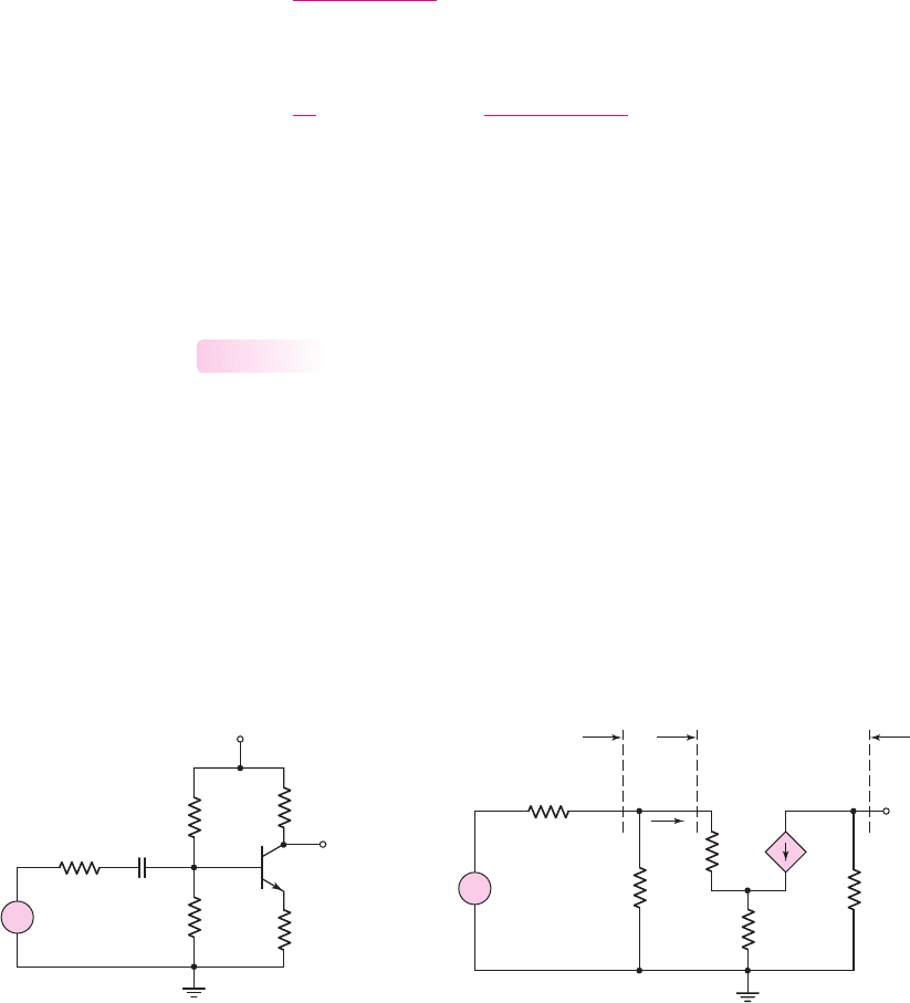
Chapter 6 Basic BJT Amplifiers 403
The two-port equivalent circuit along with the input signal source for the common-
emitter amplifier analyzed in this example is shown in Figure 6.30. We can deter-
mine the effect of the source resistance
R
S
in conjunction with the amplifier input
resistance
R
i
. Using a voltage-divider equation, we find the input voltage to the
amplifier is
V
in
=
R
i
R
i
+ R
S
· V
s
= (0.942) · V
s
The actual input voltage to the amplifier
V
in
is reduced compared to the input signal.
This is called a loading effect. In this case, the input voltage is approximately 94
percent of the signal voltage.
+
–
+
–
V
in
V
s
R
o
R
S
R
i
+
–
V
o
+
–
A
v
V
in
Figure 6.30 Two-port equivalent circuit for the amplifier in Example 6.5
COMPUTER ANALYSIS EXERCISE
PS 6.1: (a) Verify the results of Example 6.5 with a PSpice analysis. Use a stan-
dard 2N2222 transistor, for example. (b) Repeat part (a) for
R
E
= 0.3k
.
EXERCISE PROBLEM
Ex 6.5: For the circuit in Figure 6.31, let
R
E
= 0.6k
,
R
C
= 5.6k
,
β = 120
,
V
BE
(on) = 0.7
V,
R
1
= 250 k
, and
R
2
= 75 k
. (a) For
V
A
=∞
, determine the
small-signal voltage gain
A
v
. (b) Determine the input resistance looking into the
base of the transistor. (Ans. (a)
A
v
=−8.27
, (b)
R
ib
= 80.1k
)
nea80644_ch06_369-468.qxd 06/13/2009 07:32 PM Page 403 F506 Hard disk:Desktop Folder:Rakesh:MHDQ134-06:
404 Part 1 Semiconductor Devices and Basic Applications
EXAMPLE 6.6
Objective: Analyze a pnp transistor circuit.
Consider the circuit shown in Figure 6.32(a). Determine the quiescent para-
meter values and then the small-signal voltage gain. The transistor parameters are
V
EB
(on) = 0.7
V,
β = 80
, and
V
A
=∞
.
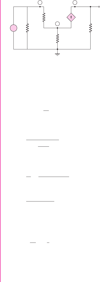
Solution (dc analysis): The dc equivalent circuit with the Thevenin equivalent circuit
of the base biasing is shown in Figure 6.32(b). We find
R
TH
= R
1
R
2
= 4060 = 24 k
R
1
=
40 kΩ
R
E
=
2 kΩ
R
C
=
4 kΩ
R
2
=
60 kΩ
v
s
v
o
V
+
= 2.5 V
V
–
= –2.5 V
C
C
+
–
+
–
R
E
=
2 kΩ
R
C
=
4 kΩ
2.5 V
–2.5 V
+
–
V
TH
+
–
V
ECQ
I
BQ
R
TH
I
EQ
I
CQ
Figure 6.32 (a) pnp transistor circuit for Example 6.6 and (b) Thevenin equivalent circuit for
Example 6.6
and
V
TH
=
R
2
R
1
+ R
2
(5) − 2.5 = 0.5 V
The transistor quiescent values are found to be
I
CQ
= 0.559
mA and
V
ECQ
= 1.63
V.
Solution (ac analysis): The small-signal hybrid-
π
parameters are as follows:
r
π
=
βV
T
I
CQ
=
(80)(0.026)
0.559
= 3.72 k
g
m
=
I
CQ
V
T
=
0.559
0.026
= 21.5 mA/V
and
r
o
=
V
A
I
Q
=∞
The small-signal equivalent circuit is shown in Figure 6.33. As noted before, we
start with the three terminals of the transistor, sketch the hybrid-
π
equivalent circuit
between these three terminals, and then put in the other circuit elements around the
transistor.
nea80644_ch06_369-468.qxd 06/13/2009 07:32 PM Page 404 F506 Hard disk:Desktop Folder:Rakesh:MHDQ134-06:
Chapter 6 Basic BJT Amplifiers 405
The output voltage is
V
o
= g
m
V
π
R
C
Writing a KVL equation from the input around the B–E loop, we find
V
s
=−V
π
−
V
π
r
π
+ g
m
V
π
R
E
The term in the parenthesis is the total current through the
R
E
resistor. Solving for
V
π
and recalling that
g
m
r
π
= β
, we obtain
V
π
=
−V
s
1 +
1 + β
r
π
R
E
Substituting into the expression for the output voltage, we find the small-signal volt-
age gain as
A
v
=
V
o
V
s
=
−β R
C
r
π
+(1 +β)R
E
Then
A
v
=
−(80)(4)
3.72 + (81)(2)
=−1.93
The negative sign indicates that the output voltage is 180 degrees out of phase with
respect to the input voltage. This same result was found in common-emitter circuits
using npn transistors.
Using the approximation given by Equation (6.59), we have
A
v
∼
=
−
R
C
R
E
=−
4
2
=−2
This approximation is very close to the actual value of gain calculated.
Comment: In the previous chapter, we found that including an emitter resistor
provided stability in the Q-point. However, we may note that in the small-signal
analysis, the
R
E
resistor reduces the small-signal voltage gain substantially. There
are almost always trade-offs to be made in electronic design.
R
E
R
C
g
m
V
p
V
s
V
o
R
1
⎜⎜ R
2
+
–
V
p
r
p
E
CB
+
–
Figure 6.33 Small-signal equivalent circuit for circuit shown in Figure 6.32(a) used in
Example 6.6
nea80644_ch06_369-468.qxd 06/13/2009 07:32 PM Page 405 F506 Hard disk:Desktop Folder:Rakesh:MHDQ134-06:
R
2
R
1
R
E
R
C
R
L
v
s
v
O
V
CC
= 12 V
C
C1
C
C2
+
–
+
–
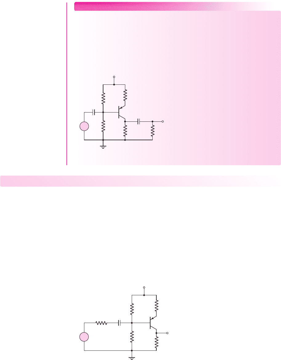
Figure 6.34 Figure for Exercise Ex 6.6
406
Part 1 Semiconductor Devices and Basic Applications
Test Your Understanding
TYU 6.3 The parameters of the circuit shown in Figure 6.28 are
V
CC
= 5
V,
R
C
= 4
k
,
R
E
= 0.25
k
,
R
S
= 0.25
k
,
R
1
= 100
k
, and
R
2
= 25
k
. The
transistor parameters are
β = 120
,
V
BE
(on) = 0.7
V, and
V
A
=∞
. Determine the
small-signal voltage gain. (Ans.
A
v
=−13.6)
TYU 6.4 For the circuit shown in Figure 6.31, let
β = 100
,
V
BE
(on) = 0.7V
, and
V
A
=∞
. Design a bias-stable circuit such that
I
CQ
= 0.5
mA,
V
CEQ
= 2.5
V, and
A
v
=−8
. (Ans. To a good approximation:
R
C
= 4.54 k
,
R
E
= 0.454 k
,
R
1
= 24.1k
, and
R
2
= 5.67 k
)
TYU 6.5 Design the circuit in Figure 6.35 such that it is bias stable and the small-
signal voltage gain is
A
v
=−8
. Let
I
CQ
= 0.6
mA,
V
ECQ
= 3.75
V,
β = 100
,
EXERCISE PROBLEM
Ex 6.6: The circuit shown in Figure 6.34 has parameters
R
E
= 0.3
k
,
R
C
= 4
k
,
R
1
= 14.4
k
,
R
2
= 110
k
and
R
L
= 10
k
. The transistor para-
meters are
β = 100
,
V
EB
(on) = 0.7
V, and
V
A
=∞
. (a) Determine the quiescent
values
I
CQ
and
V
ECQ
. (b) Find the small-signal parameters
g
m
,
r
π
, and
r
o
. (c) De-
termine the small-signal voltage gain. (Ans. (a)
I
CQ
= 1.6
mA,
V
ECQ
= 5.11
V;
(b)
g
m
= 61.54
mA/V,
r
π
= 1.625
k
,
r
o
=∞
; (c)
A
v
=−8.95)
.
R
2
R
1
R
E
R
S
= 0.25 kΩ
R
C
v
s
v
O
V
CC
= 7.5 V
C
C
+
–
+
–
Figure 6.35 Figure for Exercise TYU 6.5
nea80644_ch06_369-468.qxd 06/13/2009 08:23 PM Page 406 F506 Hard disk:Desktop Folder:Rakesh:MHDQ134-06:
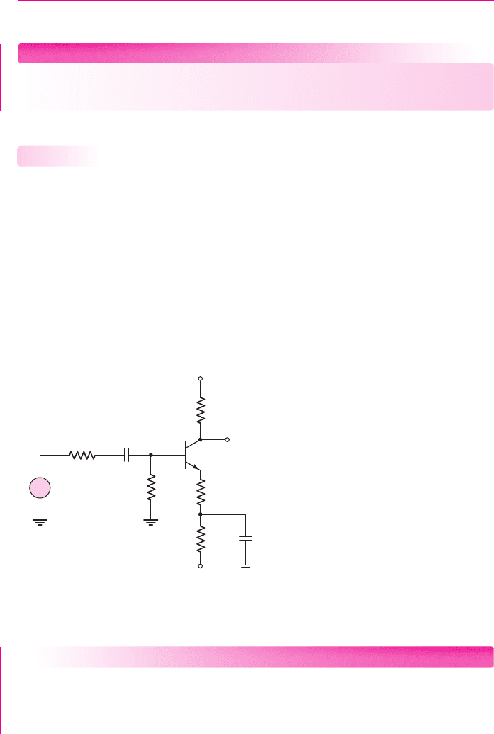
Chapter 6 Basic BJT Amplifiers 407
V
EB
(on) = 0.7
V, and
V
A
=∞
. (Ans. To a good approximation:
R
C
= 5.62 k
,
R
E
= 0.625 k
,
R
1
= 7.41 k
, and
R
2
= 42.5k
)
TYU 6.6 For the circuit in Figure 6.28, the small-signal voltage gain is given approxi-
mately by
−R
C
/R
E
. For the case of
R
C
= 2k
,
R
E
= 0.4k
, and
R
S
= 0
,what
must be the value of
β
such that the approximate value is within 5 percent of the
actual value? (Ans.
β = 76
)
COMPUTER ANALYSIS EXERCISE
PS 6.2: Verify the results of Example 6.6 with a PSpice analysis. Use a standard
transistor.
Circuit with Emitter Bypass Capacitor
There may be times when the emitter resistor must be large for the purposes of dc de-
sign, but degrades the small-signal voltage gain too severely. We can use an emitter
bypass capacitor to effectively short out a portion or all of the emitter resistance as
seen by the ac signals. Consider the circuit shown in Figure 6.36 biased with both
positive and negative voltages. Both emitter resistors
R
E1
and
R
E2
are factors in the
dc design of the circuit, but only
R
E1
is part of the ac equivalent circuit, since
C
E
pro-
vides a short circuit to ground for the ac signals. To summarize, the ac gain stability
is due only to
R
E1
and most of the dc stability is due to
R
E2
.
6.4.3
V
+
= +5 V
V
–
= –5 V
v
s
v
O
C
C
C
E
R
B
=
100 kΩ
R
E1
R
E2
R
S
= 0.5 kΩ
R
C
+
–
Figure 6.36 A bipolar circuit with an emitter resistor and an emitter bypass capacitor
DESIGN EXAMPLE 6.7
Objective: Design a bipolar amplifier to meet a set of specifications.
Specifications: The circuit configuration to be designed is shown in Figure 6.36
and is to amplify a 12 mV sinusoidal signal from a microphone to a 0.4 V sinusoidal
nea80644_ch06_369-468.qxd 06/13/2009 07:32 PM Page 407 F506 Hard disk:Desktop Folder:Rakesh:MHDQ134-06: