Neamen D. Microelectronics: Circuit Analysis and Design
Подождите немного. Документ загружается.

388 Part 1 Semiconductor Devices and Basic Applications
input control voltage
V
π
is reversed, then the direction of the current from the
dependent current source is also reversed. This change is shown in Figure 6.16(b).
We may note that this small-signal equivalent circuit is the same as the hybrid-
π
equivalent circuit for the npn transistor.
However, the author prefers to use the models shown in Figure 6.15 because the
current directions and voltage polarities are consistent with the pnp device.
Combining the hybrid-
π
model of the pnp transistor (Figure 6.15(a)) with the ac
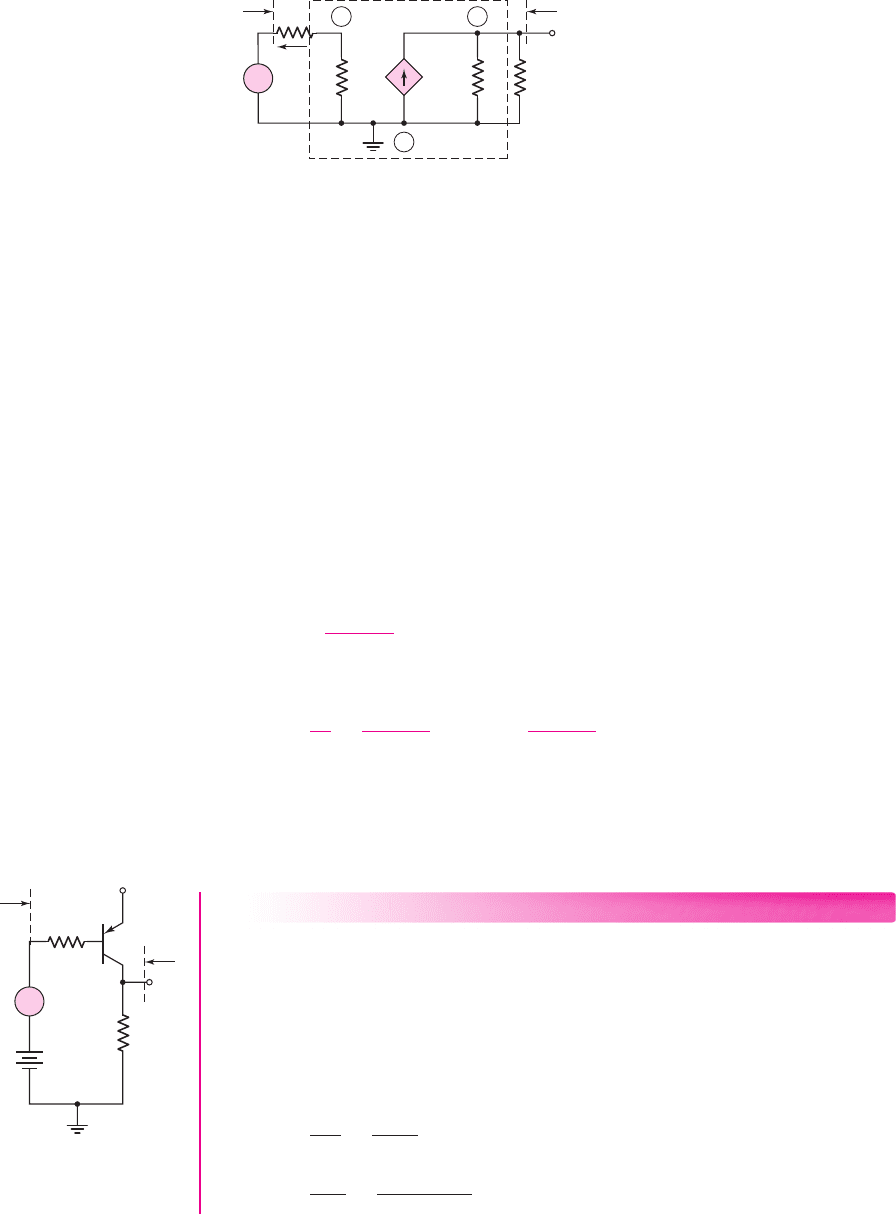
equivalent circuit (Figure 6.14(b)), we obtain the small-signal equivalent circuit
shown in Figure 6.17. The output voltage is given by
V
o
= (g
m
V
π
)(r
o
R
C
)
(6.38)
The control voltage
V
π
can be expressed in terms of the input signal voltage
V
s
using
a voltage divider equation. Taking into account the polarity, we find
V
π
=−
V
s
r
π
R
B
+r
π
(6.39)
Combining Equations (6.38) and (6.39), we obtain the small-signal voltage gain:
A
v
=
V
o
V
s
=
−g
m
r
π
R
B
+r
π
(r
o
R
C
) =
−β
R
B
+r
π
(r
o
R
C
)
(6.40)
The expression for the small-signal voltage gain of the circuit containing a pnp tran-
sistor is exactly the same as that for the npn transistor circuit. Taking into account the re-
versed current directions and voltage polarities, the voltage gain still contains a negative
sign indicating a 180-degree phase shift between the input and output signals.
EXAMPLE 6.3
Objective: Analyze a pnp amplifier circuit.
Consider the circuit shown in Figure 6.18. Assume transistor parameters of
β = 80
,
V
EB
(on) = 0.7
V, and
V
A
=∞
.
Solution (dc analysis): The
Q
-point values are found to be
I
CQ
= 1.04
mA and
V
ECQ
= 1.88
V. The transistor is biased in the forward-active mode.
Solution (ac analysis): The small-signal hybrid-
π
parameters are found to be
g
m
=
I
CQ
V
T
=
1.04
0.026
= 40 mA/V
r
π
=
βV
T
I
CQ
=
(80)(0.026)
1.04
= 2k
v
O
v
s
V
+
= 5 V
+
–
R
B
= 50 kΩ
R
C
= 3 kΩ
+
–
V
BB
=
3.65 V
R
o
R
i
Figure 6. 18 pnp common-
emitter circuit for
Example 6.3
+
–
V
p
V
o
r
o
g
m
V
p
V
s
R
C
r
p
I
b
R
B
R
i
R
o
+
–
B C
E
Figure 6.17 The small-signal equivalent circuit of the common-emitter circuit with a pnp
transistor. The small-signal hybrid-
π
equivalent circuit model of the pnp transistor is shown
within the dashed lines.
nea80644_ch06_369-468.qxd 06/13/2009 07:32 PM Page 388 F506 Hard disk:Desktop Folder:Rakesh:MHDQ134-06:

Chapter 6 Basic BJT Amplifiers 389
and
r
o
=
V
A
I
CQ
=
∞
1.04
=∞
The small-signal equivalent circuit is the same as shown in Figure 6.17. With
r
o
=∞
,
the small-signal output voltage is
V
o
= (g
m
V
π
)R
C
and we have
V
π
=−
r
π
r
π
+ R
B
· V
s
Noting that
β = g
m
r
π
, we find the small-signal voltage gain to be
A
v
=
V
o
V
s
=
−β R
C
r
π
+ R
B
=
−(80)(3)
2 + 50
or
A
v
=−4.62
The small-signal input resistance seen by the signal source (see Figure 6.17) is
R
i
= R
B
+r
π
= 50 +2 = 52
k
The small-signal output resistance looking back into the output terminal is
R
o
= R
C
r
o
= 3∞ = 3
k
Comment: We again note the
−
180° phase shift between the output and input sig-
nals. We may also note that the base resistance
R
B
in the denominator substantially
reduces the magnitude of the small-signal voltage gain. We can also note that placing
the pnp transistor in this configuration allows us to use positive power supplies.
EXERCISE PROBLEM
Ex 6.3: For the circuit in Figure 6.14(a), let
β = 90
,
V
A
= 120
V,
V
CC
= 5
V,
V
EB
(on) = 0.7
V,
R
C
= 2.5
k
,
R
B
= 50
k
, and
V
BB
= 1.145
V. (a) Determine
the small-signal hybrid-
π
parameters
r
π
,
g
m
, and
r
o
. (b) Find the small-signal
voltage gain
A
v
= V
o
/V
s
. (Ans. (a)
g
m
= 30.8
mA/V,
r
π
= 2.92
k
,
r
o
=
150 k
(b)
A
v
=−4.18)
Test Your Understanding
TYU 6.1 Using the circuit and transistor parameters given in Exercise Ex 6.1, find
i
B
,
v
BE
, and
v
CE
for
v
s
= 0.065 sin ωt
V. (Ans.
i
B
= 0.833 +0.308 sin ω t μ
A,
v
BE
= 0.7 +0.00960 sin ω t
V,
v
CE
= 1.8 −0.554 sin ω t
V)
TYU 6.2 Consider the circuit in Figure 6.18. The circuit parameters are
V
+
= 3.3
V,
V
BB
= 2.455
V,
R
B
= 80
k
, and
R
C
= 7
k
. The transistor parameters are
β = 110
,
V
EB
(on) = 0.7V
, and
V
A
= 80
V. (a) Determine
I
CQ
and
V
ECQ
. (b) Find
g
m
,
r
π
, and
r
o
. (c) Determine the small-signal voltage gain
A
v
= v
o
/v
s
. (d) Find the
small-signal input and output resistances
R
i
and
R
o
, respectively. (Ans. (a)
I
CQ
= 0.2
mA,
V
ECQ
= 1.9
V; (b)
g
m
= 7.692
mA/V,
r
π
= 14.3
k
,
r
o
= 400
k
;
(c)
A
v
=−8.02
; (d)
R
i
= 94.3
k
,
R
o
= 6.88
k
)
nea80644_ch06_369-468.qxd 06/13/2009 07:32 PM Page 389 F506 Hard disk:Desktop Folder:Rakesh:MHDQ134-06:

390 Part 1 Semiconductor Devices and Basic Applications
Expanded Hybrid-π Equivalent Circuit
1
Figure 6.19 shows an expanded hybrid-
π
equivalent circuit, which includes two
additional resistances,
r
b
and
r
μ
.
The parameter
r
b
is the series resistance of the semiconductor material between the
external base terminal B and an idealized internal base region B
. Typically,
r
b
is a few
tens of ohms and is usually much smaller than
r
π
; therefore,
r
b
is normally negligible (a
short circuit) at low frequencies. However, at high frequencies,
r
b
may not be negligible,
since the input impedance becomes capacitive, as we will see in Chapter 7.
*6.2.5
+
–
V
p
r
o
g
m
V
p
r
b
B'
r
p
r
m
E
B C
Figure 6.19 Expanded hybrid-
π
equivalent circuit
*Sections can be skipped without loss of continuity.
The parameter
r
μ
is the reverse-biased diffusion resistance of the base–collector
junction. This resistance is typically on the order of megohms and can normally be
neglected (an open circuit). However, the resistance does provide some feedback be-
tween the output and input, meaning that the base current is a slight function of the
collector–emitter voltage.
In this text, when we use the hybrid-
π
equivalent circuit model, we will neglect
both
r
b
and
r
μ
, unless they are specifically included.
Other Small-Signal Parameters
and Equivalent Circuits
Other small-signal parameters can be developed to model the bipolar transistor or
other transistors described in the following chapters.
One common equivalent circuit model for bipolar transistor uses the h-
parameters, which relate the small-signal terminal currents and voltages of a two-
port network. These parameters are normally given in bipolar transistor data sheets,
and are convenient to determine experimentally at low frequency.
Figure 6.20(a) shows the small-signal terminal current and voltage phasors for a
common-emitter transistor. If we assume the transistor is biased at a Q-point in the
forward-active region, the linear relationships between the small-signal terminal cur-
rents and voltages can be written as
V
be
= h
ie
I
b
+ h
re
V
ce
(6.41(a))
I
c
= h
fe
I
b
+ h
oe
V
ce
(6.41(b))
These are the defining equations of the common–emitter h-parameters, where the
subscripts are: i for input, r for reverse, f for forward, o for output, and e for common
emitter.
*6.2.6
nea80644_ch06_369-468.qxd 06/13/2009 07:32 PM Page 390 F506 Hard disk:Desktop Folder:Rakesh:MHDQ134-06:
Chapter 6 Basic BJT Amplifiers 391
(a)
I
b
I
c
V
be
V
ce
+
–
+
–
(b)
+
–
V
ce
+
–
V
be
h
re
V
ce
h
fe
I
b
h
ie
I
b
I
c
E
B C
+
–
h
oe
1
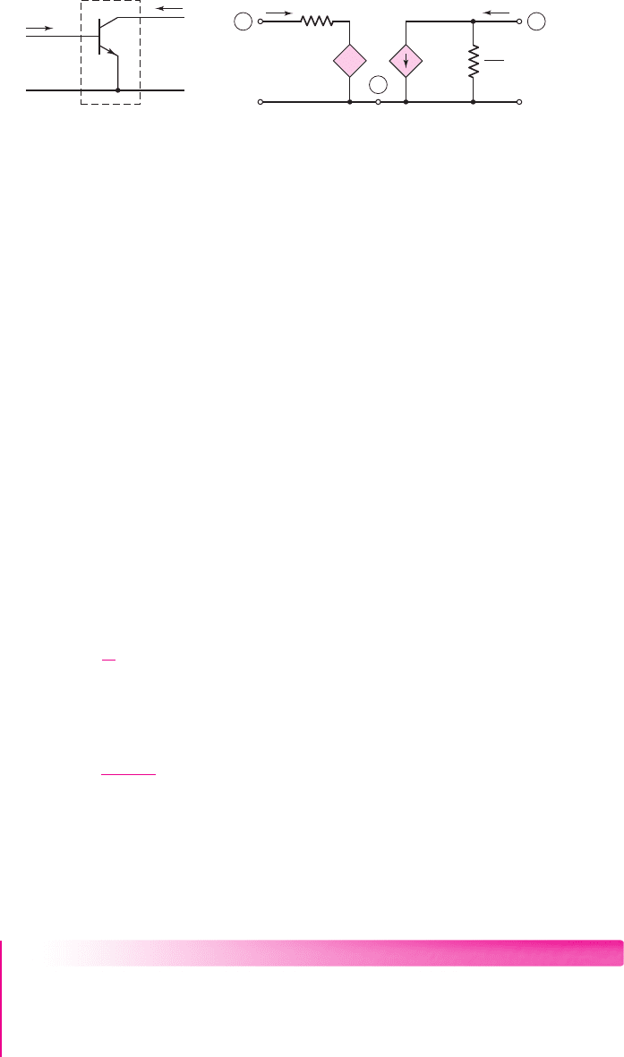
Figure 6.20 (a) Common-emitter npn transistor and (b) the h-parameter model of the
common-emitter bipolar transistor
These equations can be used to generate the small-signal h-parameter equivalent
circuit, as shown in Figure 6.20(b). Equation (6.41(a)) represents a Kirchhoff voltage
law equation at the input, and the resistance
h
ie
is in series with a dependent voltage
source equal to
h
re
V
ce
. Equation (6.41(b)) represents a Kirchhoff current law equa-
tion at the output, and the conductance
h
oe
is in parallel with a dependent current
source equal to
h
fe
I
b
.
Since both the hybrid-
π
and h-parameters can be used to model the
characteristics of the same transistor, these parameters are not independent. We
can relate the hybrid-
π
and h-parameters using the equivalent circuit shown in
Figure 6.19.
We can show the small-signal input resistance
h
ie
is
h
ie
= r
b
+r
π
r
μ
∼
=
r
π
(6.42)
The parameter
h
fe
is the small-signal current gain and is
found to be
h
fe
= g
m
r
π
= β
(6.43)
The small-signal output admittance
h
oe
is given by
h
oe
∼
=
1
r
o
(6.44)
The fourth
h
-parameter,
h
re
, is called the voltage feedback ratio and can be
written as
h
re
=
r
π
r
π
+r
μ
≈ 0
(6.45)
The h-parameters for a pnp transistor are defined in the same way as those for
an npn device. Also, the small-signal equivalent circuit for a pnp transistor using
h-parameters is identical to that of an npn device, except that the current directions
and voltage polarities are reversed.
EXAMPLE 6.4
Objective: Determine the h-parameters of a specific transistor.
The 2N2222A transistor is a commonly used discrete npn transistor. Data for
this transistor are shown in Figure 6.21. Assume the transistor is biased at
I
C
= 1
mA
and let
T = 300
K.
nea80644_ch06_369-468.qxd 06/13/2009 07:32 PM Page 391 F506 Hard disk:Desktop Folder:Rakesh:MHDQ134-06:
392 Part 1 Semiconductor Devices and Basic Applications
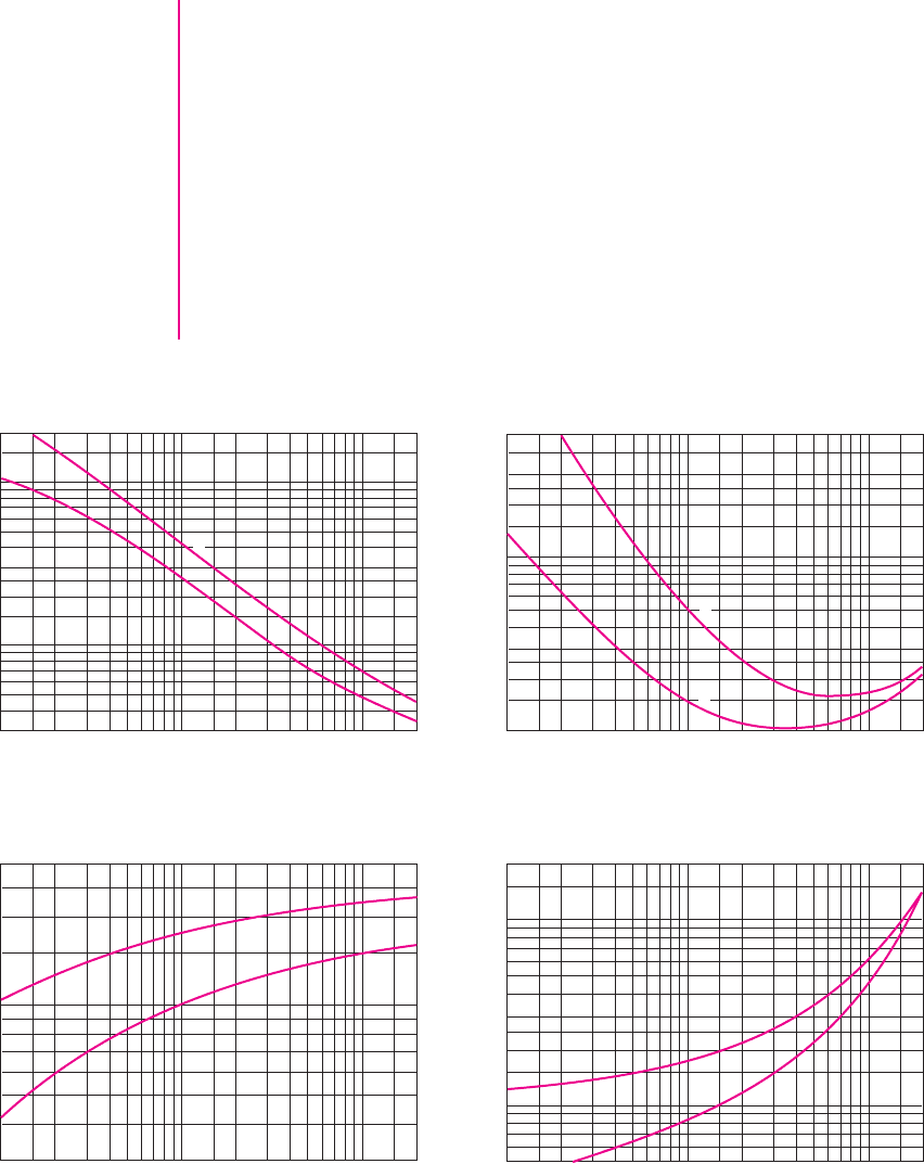
Solution: In Figure 6.21, we see that the small-signal current gain
h
fe
is generally in
the range
100 < h
fe
< 170
for
I
C
= 1
mA, and the corresponding value of
h
ie
is
generally between 2.5 and 5 k
. The voltage feedback ratio
h
re
varies between
1.5 × 10
−4
and
5 × 10
−4
, and the output admittance
h
oe
is in the range
8 < h
oe
<
18
μ
mhos.
Comment: The purpose of this example is to show that the parameters of a given
transistor type can vary widely. In particular, the current gain parameter can easily
vary by a factor of two. These variations are due to tolerances in the initial semicon-
ductor properties and in the production process variables.
Design Pointer: This example clearly shows that there can be a wide variation in
transistor parameters. Normally, a circuit is designed using nominal parameter val-
ues, but the allowable variations must be taken into account. In Chapter 5, we noted
2
I
C
collector current (mA dc)
h
ie
Input impedance (kΩ)
Input impedance
0.3
0.1 0.2 0.5 1.0 2.0 5.0 10 20 0.1 0.2 0.5 1.0 2.0 5.0 10 20
0.1 0.2 0.5 1.0 2.0 5.0 10 20 0.1 0.2 0.5 1.0 2.0 5.0 10 20
0.5
0.7
1.0
2.0
3.0
5.0
7.0
10
20
1
I
C
collector current (mA dc)
h
re
Voltage feedback ratio (× 10
–4
)
h
oe
Output admittance (m mhos)
Voltage feedback ratio
1.0
2.0
3.0
5.0
10
20
30
50
1
2
I
C
collector current (mA dc)
h
fe
Current gain
Current gain
30
50
70
100
200
300
2
I
C
collector current (mA dc)
Output admittance
5.0
10
20
50
100
200
1
(a) (b)
(c) (d)
1
2
Figure 6.21 h-parameter data for the 2N2222A transistor. Curves 1 and 2 represent data
from high-gain and low-gain transistors, respectively.
nea80644_ch06_369-468.qxd 06/13/2009 07:32 PM Page 392 F506 Hard disk:Desktop Folder:Rakesh:MHDQ134-06:

Chapter 6 Basic BJT Amplifiers 393
how a variation in
β
affects the Q-point. In this chapter, we will see how the varia-
tions in small-signal parameters affect the small-signal voltage gain and other char-
acteristics of a linear amplifier.
EXERCISE PROBLEM
Ex 6.4: Repeat Example 6.4 if the quiescent collector current is (a)
I
CQ
= 0.2
mA
and (b)
I
CQ
= 5
mA. [Ans. (a)
7.8 < h
ie
< 15
k
,
6.2 × 10
−4
< h
re
< 50 ×
10
−4
,
60 < h
fe
< 125
,
5 < h
oe
< 13 μ
mhos; (b)
0.7 < h
ie
< 1.1
k
,
1.05 ×
10
−4
< h
re
< 1.6 ×10
−4
,
140 < h
fe
< 210
,
22 < h
oe
< 35 μ
mhos)
In the previous discussion, we indicated that the h-parameters
h
ie
and 1/h
oe
are
essentially equivalent to the hybrid-
π
parameters
r
π
and
r
o
, respectively, and that
h
fe
is essentially equal to
β
. The transistor circuit response is independent of the
transistor model used. This reinforces the concept of a relationship between hybrid-
π
parameters and h-parameters. In fact, this is true for any set of small-signal para-
meters; that is, any given set of small-signal parameters is related to any other set of
parameters.
Data Sheet
In the previous example, we showed some data for the 2N2222 discrete transistor.
Figure 6.22 shows additional data from the data sheet for this transistor. Data sheets
contain a lot of information, but we can begin to discuss some of the data at this time.
The first set of parameters pertains to the transistor in cutoff. The first two para-
meters listed are
V
(BR)CEO
and
V
(BR)CBO
, which are the collector–emitter break-
down voltage with the base terminal open and the collector–base breakdown voltage
with the emitter open. These parameters were discussed in Section 5.1.6 in the last
chapter. In that section, we argued that
V
(BR)CBO
was larger than
V
(BR)CEO
, which is
supported by the data shown. These two voltages are measured at a specific current
in the breakdown region. The third parameter,
V
(BR)EBO
, is the emitter–base break-
down voltage, which is substantially less than the collector–base or collector–emitter
breakdown voltages.
The current
I
CBO
is the reverse-biased collector–base junction current with
the emitter open
(I
E
= 0)
. This parameter was also discussed in Section 5.1.6. In
the data sheet, this current is measured at two values of collector–base voltage and
at two temperatures. The reverse-biased current increases with increasing temper-
ature, as we would expect. The current
I
EBO
is the reverse-biased emitter–base
junction current with the collector open
(I
C
= 0)
. This current is also measured at
a specific reverse-bias voltage. The other two current parameters,
I
CEX
and
I
BL
,
are the collector current and base current measured at given specific cutoff
voltages.
The next set of parameters applies to the transistor when it is turned on. As was
shown in Example 6.4, the data sheets give the h-parameters of the transistor. The
first parameter,
h
FE
, is the dc common-emitter current gain and is measured over a
wide range of collector current. We discussed, in Section 5.4.2, stabilizing the
Q-point against variations in current gain. The data presented in the data sheet show
that the current gain for a given transistor can vary significantly, so that stabilizing
the Q-point is indeed an important issue.
We have used
V
CE
(sat) as one of the piecewise linear parameters when a tran-
sistor is driven into saturation and have always assumed a particular value in our
nea80644_ch06_369-468.qxd 06/13/2009 07:32 PM Page 393 F506 Hard disk:Desktop Folder:Rakesh:MHDQ134-06:

394 Part 1 Semiconductor Devices and Basic Applications
National
Semiconductor
2N2222
2N2222A
PN2222
PN2222A
MMBT2222
MMBT2222A
MPQ2222
TO–18 TO–92 TO–236
(SOT–23)
TO –116
C
C
C
C
B
B
B
B
E
E
E
E
14
1
NPN General Purpose Amplifier
Electrical Characteristics
T
A
= 25 °C unless otherwise noted
Parameter
Symbol
OFF CHARACTERISTICS
Min Max Units
Collector-Emitter Breakdown Voltage (Note 1)
(
I
C
= 10 mA, I
B
= 0)
Collector-Base Breakdown Voltage
(I
C
= 10 mA, I
E
= 0)
Emitter Base Breakdown Voltage
(
I
E
= 10 mA, I
C
= 0)
2222
2222A
2222
2222A
2222
2222A
2222A
2222A
2222A
2222
2222A
2222
2222A
2222
2222A
I
CEX
I
CBO
I
EBO
I
BL
Collector Cutoff Current
(V
CE
= 60 V,
V
EB
(off) = 3.0 V)
Collector Cutoff Current
(V
CB
= 50 V,
I
E
= 0)
(
V
CB
= 60 V, I
E
= 0)
(
V
CB
= 50 V, I
E
= 0, T
A
= 150 °C)
(
V
CB
= 60 V, I
E
= 0, T
A
= 150 °C)
Emitter Cutoff Current
(
V
EB
= 3.0 V, I
C
= 0)
Base Cutoff Current
(V
CE
= 60 V, V
EB
(off ) = 3.0)
DC Current Gain
(
I
C
= 0.1 mA, V
CE
= 10 V)
(
I
C
= 1.0 mA, V
CE
= 10 V)
(
I
C
= 10 mA, V
CE
= 10 V)
(
I
C
= 10 mA, V
CE
= 10 V, T
A
= –55 °C)
(
I
C
= 150 mA, V
CE
= 10 V) (Note 1)
(
I
C
= 150 mA, V
CE
= 1.0 V) (Note 1)
(
I
C
= 500 mA, V
CE
= 10 V) (Note 1)
h
FE
Note 1: Pulse Test: Pulse Width ≤ 300 m s, Duty Cycle ≤ 2.0%.
ON CHARACTERISTICS
35
50
75
35
100
50
30
40
300
20
10
0.01
0.01
10
10
mA
nA
nA
nA
30
40
60
75
5.0
6.0
V
V
V
10
2N2222/PN2222/MMBT2222/MPQ2222/2N2222A/PN2222A/MMBT2222A NPN General Purpose Amplifier
V
(BR )CEO
V
(BR )CBO
V
(BR )EBO
Figure 6.22 Basic data sheet for the 2N2222 bipolar transistor
nea80644_ch06_369-468.qxd 06/13/2009 07:32 PM Page 394 F506 Hard disk:Desktop Folder:Rakesh:MHDQ134-06:

Chapter 6 Basic BJT Amplifiers 395
2222
2222A
Note 1: Pulse Test: Pulse Width < 300 m s, Duty Cycle ≤ 2.0%.
Note 2: For characteristics curves, see Process 19.
Note 3: f
T
is defined as the frequency at which h
fe
extrapolates to unity.
NPN General Purpose Amplifier (Continued)
Electrical Characteristics
T
A
= 25 °C unless otherwise noted (Continued)
Parameter
Symbol
ON CHARACTERISTICS (Continued)
Min Max Units
Collector-Emitter Saturation Voltage (Note 1)
(
I
C
= 150 mA, I
B
= 15 mA)
(
I
C
= 500 mA, I
B
= 50 mA)
Base-Emitter Saturation Voltage (Note 1)
(
I
C
= 150 mA, I
B
= 15 mA)
(
I
C
= 500 mA, I
B
= 50 mA)
2222A
2222A
2222
2222A
2222
2222A
2222
2222A
2222
2222A
2222
2222A
ns
ns
ns
ns
V
CE
(sat)
V
BE
(sat)
SMALL-SIGNAL CHARACTERISTICS
f
T
C
obo
C
ibo
rb'C
C
NF
Real Part of Common-Emitter
High Frequency Input Impedance
(
I
C
= 20 mA, V
CE
= 20 V, f = 300 MHz)
Noise Figure
(
I
C
= 100 mA, V
CE
= 10 V, R
S
= 1.0 kΩ, f = 1.0 kHz)
Collector Base Time Constant
(
I
E
= 20 mA, V
CB
= 20 V, f = 31.8 MHz)
Input Capacitance (Note 3)
(V
EB
= 0.5 V, I
C
= 0, f = 100 kHz)
Output Capacitance (Note 3)
(
V
CB
= 10 V, I
E
= 0, f = 100 kHz)
Current Gain—Bandwidth Product (Note 3)
(I
C
= 20 mA, V
CE
= 20 V, f = 100 MHz)
SWITCHING CHARACTERISTICS
t
D
t
R
t
S
t
F
Delay Time
Rise Time
Storage Time
Fall Time
(
V
CC
= 30 V,
V
BE
(off) = 0.5 V,
I
C
= 150 mA, I
B1
= 15 mA)
(
V
CC
= 30 V, I
C
= 150 mA,
I
B1
= I
B2
= 15 mA)
except
MPQ2222
except
MPQ2222
10
25
225
60
60
Ω
4.0
dB
150
ps
30
25
pF
8.0
pF
250
300
MHz
V
V
0.6
0.6
1.3
1.2
2.6
2.0
0.4
0.3
1.6
1.0
Re(h
ie
)
2222/PN2222/MMBT2222/MPQ2222/2N2222A/PN2222A/MMBT2222A NPN General Purpose Amplifier
Figure 6.22 (continued)
analysis or design. This parameter, listed in the data sheet, is not a constant but varies
with collector current. If the collector current becomes relatively large, then the
collector–emitter saturation voltage also becomes relatively large. The larger
V
CE
(sat) value would need to be taken into account in large-current situations. The
base–emitter voltage for a transistor driven into saturation,
V
BE
(sat), is also given.
nea80644_ch06_369-468.qxd 06/13/2009 07:32 PM Page 395 F506 Hard disk:Desktop Folder:Rakesh:MHDQ134-06:
396 Part 1 Semiconductor Devices and Basic Applications
i
c
i
e
i
b
v
be
+
–
B
E
C
g
m
v
be
= ai
e
r
e
=
V
T
I
E
Figure 6.23 The T-model of
an npn bipolar transistor
+
–
R
S
R
S
v
s
i
s
(a) (b)
Figure 6.24. Input signal source modeled as (a) Thevenin equivalent circuit and (b) Norton
equivalent circuit
Up to this point in the text, we have not been concerned with this parameter; how-
ever, the data sheet shows that the base–emitter voltage can increase significantly
when a transistor is driven into saturation at high current levels.
The other parameters listed in the data sheet become more applicable later in the
text when the frequency response of transistors is discussed. The intent of this short
discussion is to show that we can begin to read through data sheets even though there
are a lot of data presented.
The T-model: The hybrid-pi model can be used to analyze the time-varying char-
acteristics of all transistor circuits. We have briefly discussed the h-parameter model
of the transistor. The h-parameters of this model are often given in data sheets for
discrete transistors. Another small-signal model of the transistor, the T-model, is
shown in Figure 6.23. This model might be convenient to use in specific applications.
However, to avoid introducing too much confusion, we will concentrate on using the
hybrid-
π
model in this text and leave the T-model to more advanced electronics
courses.
6.3 BASIC TRANSISTOR
AMPLIFIER CONFIGURATIONS
Objective: • Discuss the three basic transistor amplifier configura-
tions and discuss the four equivalent two-port networks.
As we have seen, the bipolar transistor is a three-terminal device. Three basic single-
transistor amplifier configurations can be formed, depending on which of the three
transistor terminals is used as signal ground. These three basic configurations are
appropriately called common emitter, common collector (emitter follower), and
common base. Which configuration or amplifier is used in a particular application
depends to some extent on whether the input signal is a voltage or current and
whether the desired output signal is a voltage or current. The characteristics of the
three types of amplifiers will be determined to show the conditions under which each
amplifier is most useful.
The input signal source can be modeled as either a Thevenin or Norton equiva-
lent circuit. Figure 6.24(a) shows the Thevenin equivalent source that would repre-
sent a voltage signal, such as the output of a microphone. The voltage source
v
s
nea80644_ch06_369-468.qxd 06/13/2009 07:32 PM Page 396 F506 Hard disk:Desktop Folder:Rakesh:MHDQ134-06:
Chapter 6 Basic BJT Amplifiers 397
represents the voltage generated by the microphone. The resistance
R
S
is called the
output resistance of the source and takes into account the change in output voltage as
the source supplies current. Figure 6.24(b) shows the Norton equivalent source that
would represent a current signal, such as the output of a photodiode. The current
source
i
s
represents the current generated by the photodiode and the resistance
R
S
is
the output resistance of this signal source.
Each of the three basic transistor amplifiers can be modeled as a two-port
network in one of four configurations as shown in Table 6.3. We will determine the
gain parameters, such as
A
vo
,
A
io
,
G
mo
, and
R
mo
, for each of the three transistor am-
plifiers. These parameters are important since they determine the amplification of the
amplifier. However, we will see that the input and output resistances,
R
i
and
R
o
,are
also important in the design of these amplifiers. Although one configuration shown in
Table 6.3 may be preferable for a given application, any one of the four can be used
to model a given amplifier. Since each configuration must produce the same terminal
characteristics for a given amplifier, the various gain parameters are not independent,
but are related to each other.
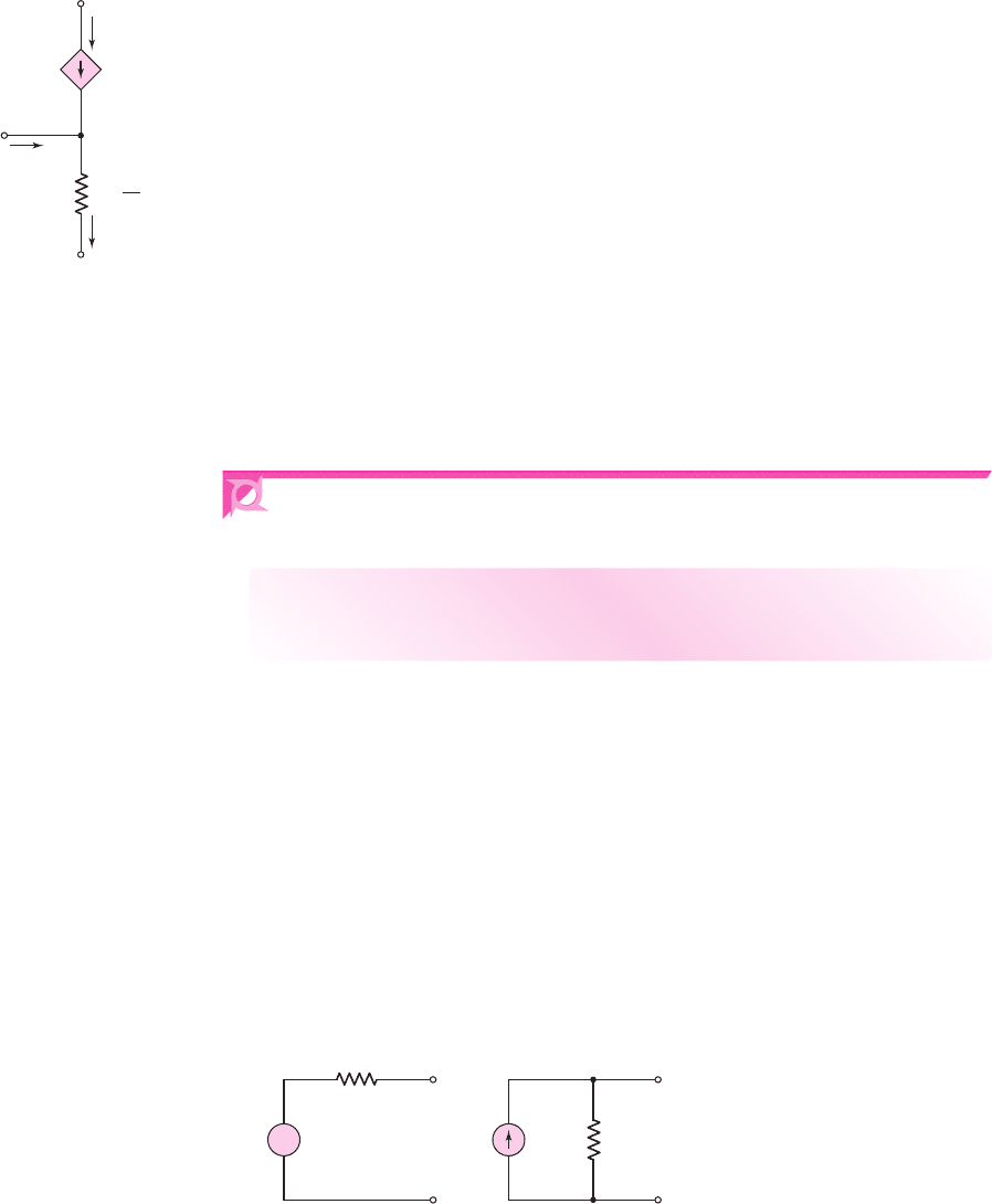
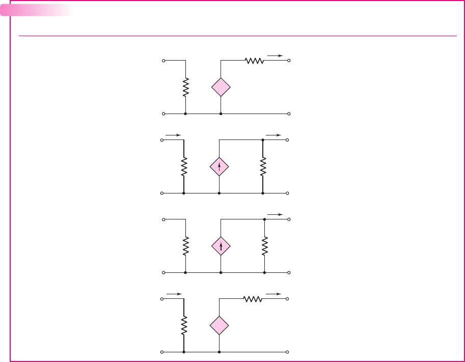
Table 6.3 Four equivalent two-port networks
Type Equivalent circuit Gain property
Voltage amplifier Output voltage proportional to
input voltage
Current amplifier Output current proportional to
input current
Transconductance amplifier Output current proportional to
input voltage
Transresistance amplifier Output voltage proportional to
input current
R
i
R
o
i
o
+
–
v
o
+
R
mo
i
in
–
i
in
R
i
i
o
R
o
v
o
+
G
ms
v
in
–
v
in
+
–
R
i
i
o
R
o
v
o
+
A
is
i
in
–
i
in
v
in
R
i
R
o
i
o
+
+
–
–
v
o
+
A
vo
v
in
–
nea80644_ch06_369-468.qxd 06/13/2009 07:32 PM Page 397 F506 Hard disk:Desktop Folder:Rakesh:MHDQ134-06: