Neamen D. Microelectronics: Circuit Analysis and Design
Подождите немного. Документ загружается.


488 Part 1 Semiconductor Devices and Basic Applications
Therefore,
|A
v
|
max
=
(69.6)(1.44)(2)
(0.1 + 6.775)
8.084
8.084 + 41.84
= 4.72
Comment: The coupling capacitor produces a high-pass network. In this circuit, if
the signal frequency is approximately two octaves above the corner frequency, the
coupling capacitor acts as a short circuit.
EXERCISE PROBLEM
Ex 7.3: For the circuit shown in Figure 7.21(a), the parameters are:
V
CC
= 3
V,
R
Si
= 0, R
1
= 110
k
,
R
2
= 42 k
,
R
E
= 0.5k
,
R
C
= 7k
, and
C
C
=
0.47 μ
F. The transistor parameters are
β = 150
,
V
BE
(on) = 0.7
V, and
V
A
=∞
.
(a) Determine the expression for and the value of the time constant
τ
S
. (b) Deter-
mine the corner frequency and midband voltage gain. (Ans. (a)
τ
S
= R
i
C
C
=
10.87
ms; (b)
f
L
= 14.6
Hz,
A
v
=−10.84)
Time Constant Technique: In general, we do not need to derive the complete cir-
cuit transfer function including capacitance effects in order to complete the Bode plot
and determine the frequency response. By looking at a circuit with, initially, only one
capacitor, we can determine if the amplifier is a low-pass or high-pass circuit. We can
then specify the Bode plot if we know the time constant and the maximum midband
gain. The time constant determines the corner frequency. The midband gain is found
in the usual way when capacitances are eliminated from the circuit.
This time constant technique yields good results when all poles are real, as will
be the case in this chapter. In addition, this technique does not determine the corner
frequencies due to system zeros. The major benefit of using the time constant ap-
proach is that it gives information about which circuit elements affect the
−3
dB fre-
quency of the circuit. A coupling capacitor produces a high-pass network, so the form
of the Bode plot will be the same as that shown in Figure 7.5. Also, the maximum
gain is determined when the coupling capacitor acts as a short circuit, as was as-
sumed in Chapters 4 and 6.
The time constant for the circuit is a function of the equivalent resistance seen
by the capacitor. The small-signal equivalent circuit is shown in Figure 7.21(b). If we
set the independent voltage source equal to zero, the equivalent resistance seen by
the coupling capacitor
C
C
is (
R
Si
+ R
i
). The time constant is then
τ
S
= (R
Si
+ R
i
)C
C
(7.38)
This is the same as Equation (7.35), which was determined by using a current–
voltage analysis.
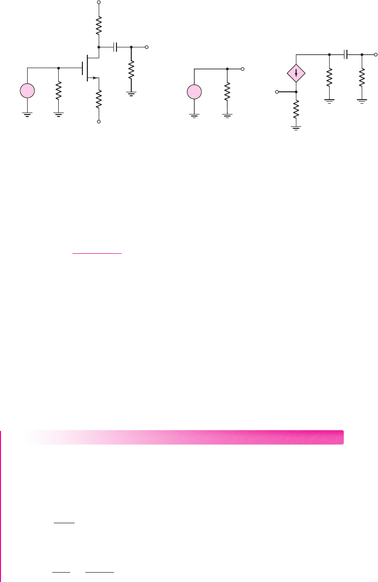
Output Coupling Capacitor: Common-Source Circuit
Figure 7.22(a) shows a common-source MOSFET amplifier. We assume that the re-
sistance of the signal generator is much less than R
G
and can therefore be neglected.
In this case, the output signal is connected to the load through a coupling capacitor.
The small-signal equivalent circuit, assuming r
o
is infinite, is shown in Fig-
ure 7.22(b). The maximum output voltage, assuming C
C
is a short circuit, is
|V
o
|
max
= g
m
V
gs
(R
D
R
L
)
(7.39)
nea80644_ch07_469-558.qxd 06/13/2009 08:07 PM Page 488 F506 Hard disk:Desktop Folder:Rakesh:MHDQ134-07:
Chapter 7 Frequency Response 489
and the input voltage can be written as
V
i
= V
gs
+ g
m
R
S
V
gs
(7.40)
Therefore, the maximum small-signal gain is
|A
v
|
max
=
g
m
(R
D
R
L
)
1 + g
m
R
S
(7.41)
Even though the coupling capacitor is in the output portion of the circuit, the
Bode plot will still be that of a high-pass network, as shown in Figure 7.5. Using the
time constant technique to determine the corner frequency will substantially simplify
the circuit analysis, since we do not specifically need to determine the transfer
function for the frequency response.
The time constant is a function of the effective resistance seen by capacitor C
C
,
which is determined by setting all independent sources equal to zero. Since
V
i
= 0
,
then
V
gs
= 0
and
g
m
V
gs
= 0
, and the effective resistance seen by C
C
is (
R
D
+ R
L
).
The time constant is then
τ
S
= (R
D
+ R
L
)C
C
(7.42)
and the corner frequency is
f
L
= 1/2πτ
S
.
DESIGN EXAMPLE 7.4
Objective: The circuit in Figure 7.22(a) is to be used as a simple audio amplifier.
Design the circuit such that the lower corner frequency is
f
L
= 20
Hz.
Solution: The corner frequency can be written in terms of the time constant, as
follows:
f
L
=
1
2πτ
S
The time constant is then
τ
S
=
1
2π f
=
1
2π(20)
⇒ 7.96 ms
(a) (b)
v
i
R
G
=
50 kΩ
C
C
+5 V
–5 V
R
S
=
5 kΩ
R
D
= 6.7 kΩ
v
o
R
L
=
10 kΩ
+
–
V
o
V
i
C
C
R
G
=
50 kΩ
+
–
V
gs
g
m
V
gs
R
L
=
10 kΩ
R
D
=
6.7 kΩ
R
S
=
5 kΩ
+
–
Figure 7.22 (a) Common-source circuit with output coupling capacitor and (b) small-signal
equivalent circuit
nea80644_ch07_469-558.qxd 06/13/2009 08:07 PM Page 489 F506 Hard disk:Desktop Folder:Rakesh:MHDQ134-07:
490 Part 1 Semiconductor Devices and Basic Applications
EXERCISE PROBLEM
Ex 7.4: Consider the circuit shown in Figure 7.22(a). The bias voltages are
changed to
V
+
= 3
V and
V
−
=−3
V. Other circuit parameters are
R
L
= 20 k
and
R
G
= 100 k
. The transistor parameters are
V
TN
= 0.4V, K
n
= 100 μA/V
2
,
and
λ = 0
. (a) Design the circuit such that
I
DQ
= 250 μ
A and
V
DSQ
= 1.7
V.
(b) If
C
C
= 0.7 μ
F, determine the corner frequency. (Ans. (a)
R
S
= 4.08 k
,
R
D
= 13.1k
; (b)
f
L
= 6.87
Hz)
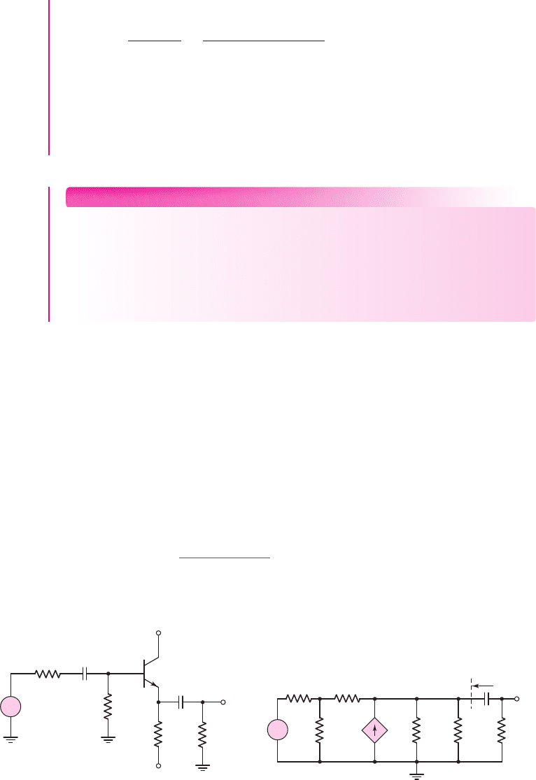
Output Coupling Capacitor: Emitter-Follower Circuit: An emitter follower with
a coupling capacitor in the output portion of the circuit is shown in Figure 7.23(a).
We assume that coupling capacitor C
C1
, which is part of the original emitter follower,
is very large, and that it acts as a short circuit to the input signal.
The small-signal equivalent circuit, including the small-signal transistor resis-
tance r
o
, is shown in Figure 7.23(b). The equivalent resistance seen by the coupling
capacitor C
C2
is [
R
o
+ R
L
], and the time constant is
τ
S
= [R
o
+ R
L
]C
C2
(7.43)
where R
o
is the output resistance as defined in Figure 7.23(b).As shown in Chapter 6,
the output resistance is
R
o
= R
E
r
o
[r
π
+(R
S
R
B
)]
1 + β
(7.44)
R
S
= 0.5 kΩ
R
B
= 100 kΩ
v
i
+10 V
–10 V
v
o
R
L
=
10 kΩ
R
E
=
10 kΩ
C
C2
r
p
g
m
V
p
R
L
=
10 kΩ
R
E
=
10 kΩ
r
o
V
i
V
o
+
–
V
p
R
S
= 0.5 kΩ
R
B
=
100 kΩ
C
C2
R
o
(a) (b)
+
–
+
–
C
C1
→ ∞
Figure 7.23 (a) Emitter-follower circuit with output coupling capacitor and (b) small-signal
equivalent circuit
Therefore, from Equation (7.42) the coupling capacitance is
C
C
=
τ
S
R
D
+ R
L
=
7.96 × 10
−3
6.7 × 10
3
+10 ×10
3
= 4.77 ×10
−7
F
or
C
C
= 0.477 μF
Comment: Using the time constant technique to find the corner frequency is sub-
stantially easier than using the circuit analysis approach.
nea80644_ch07_469-558.qxd 06/13/2009 08:07 PM Page 490 F506 Hard disk:Desktop Folder:Rakesh:MHDQ134-07:
Chapter 7 Frequency Response 491
If we combine Equations (7.44) and (7.43), the time constant expression
becomes fairly complicated. However, the current–voltage analysis of this circuit
including C
C2
is even more cumbersome. The time constant technique again simpli-
fies the analysis substantially.
EXAMPLE 7.5
Objective: Determine the 3 dB frequency of an emitter-follower amplifier circuit
with an output coupling capacitor.
Consider the circuit shown in Figure 7.23(a) with transistor parameters
β = 100
,
V
BE
(on) = 0.7
V, and
V
A
= 120
V. The output coupling capacitance is
C
C2
= 1 μ
F.
Solution: A dc analysis shows that
I
CQ
= 0.838
mA. Therefore, the small-signal
parameters are:
r
π
= 3.10 k
,
g
m
= 32.2
mA/V, and
r
o
= 143 k
.
From Equation (7.44), the output resistance R
o
of the emitter follower is
R
o
= R
E
r
o
[r
π
+(R
S
R
B
)]
1 + β
= 10143
[3.10 + (0.5100)]
101
= 101430.0356 k
∼
=
35.5
From Equation (7.43), the time constant is
τ
S
= [R
o
+ R
L
]C
C2
= [35.5 +10
4
](10
−6
)
∼
=
1 × 10
−2
s
The 3 dB frequency is then
f
L
=
1
2πτ
S
=
1
2π(10
−2
)
= 15.9Hz
Comment: Determining the 3 dB or corner frequency is very direct with the time
constant technique.
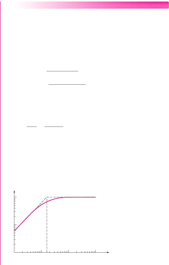
Computer Verification: Based on PSpice, analysis, Figure 7.24 is a Bode plot of the
voltage gain magnitude of the emitter-follower circuit shown in Figure 7.23(a). The
corner frequency is essentially identical to that obtained by the time constant tech-
nique. Also, the asymptotic value of the small-signal voltage gain is
A
v
= 0.988
,as
expected for an emitter-follower circuit.
f
L
f (Hz)
1 10 100 1000
0.01
0.1
|A
V
|
1.0
Figure 7.24 PSpice analysis results for the emitter-follower circuit in Figure 7.23(a)
nea80644_ch07_469-558.qxd 06/13/2009 08:07 PM Page 491 F506 Hard disk:Desktop Folder:Rakesh:MHDQ134-07:
492 Part 1 Semiconductor Devices and Basic Applications
EXERCISE PROBLEM
Ex 7.5: For the emitter-follower circuit shown in Figure 7.23(a), determine the
required value of C
C2
to yield a corner frequency of 10 Hz. (Ans.
C
C2
= 1.59 μ
F)
Problem-Solving Technique: Bode Plot of Gain Magnitude
1. For a particular capacitor in a circuit, determine whether the capacitor is pro-
ducing a low-pass or high-pass circuit. From this, sketch the general shape of
the Bode plot.
2. The corner frequency is found from
f = 1/2 πτ
where the time constant is
τ = R
eq
C
. The equivalent resistance R
eq
is the equivalent resistance seen by
the capacitor.
3. The maximum gain magnitude is the midband gain. Coupling and bypass ca-
pacitors act as short circuits and load capacitors act as open circuits.
Load Capacitor Effects
An amplifier output may be connected to a load or to the input or another amplifier.
The model of the load circuit input impedance is generally a capacitance in parallel
with a resistance. In addition, there is a parasitic capacitance between ground and the
line that connects the amplifier output to the load circuit.
Figure 7.25(a) shows a MOSFET common-source amplifier with a load resis-
tance R
L
and a load capacitance C
L
connected to the output, and Figure 7.25(b) shows
the small-signal equivalent circuit. The transistor small-signal output resistance r
o
is
assumed to be infinite. This circuit configuration is essentially the same as that in
Figure 7.3, which is a low-pass network. At high frequencies, the impedance of C
L
decreases and acts as a shunt between the output and ground, and the output voltage
tends toward zero. The Bode plot is similar to that shown in Figure 7.8, with an upper
corner frequency and a maximum gain asymptote.
7.3.2
v
i
R
G
=
200 kΩ
C
L
+5 V
–5 V
R
D
R
S
v
O
R
L
V
o
V
i
C
L
R
G
=
200 kΩ
+
–
V
sg
g
m
V
sg
R
L
R
D
R
S
(a) (b)
+
–
+
–
Figure 7.25 (a) MOSFET common-source circuit with a load capacitor and (b) small-signal
equivalent circuit
nea80644_ch07_469-558.qxd 06/13/2009 08:07 PM Page 492 F506 Hard disk:Desktop Folder:Rakesh:MHDQ134-07:
Chapter 7 Frequency Response 493
The equivalent resistance seen by the load capacitor C
L
is
R
D
R
L
. Since we set
V
i
= 0
, then
g
m
V
sg
= 0
, which means that the dependent current source does not
affect the equivalent resistance.
The time constant for this circuit is
τ
P
= (R
D
R
L
)C
L
(7.45)
The maximum gain asymptote, which is found by assuming C
L
is an open
circuit, is
|A
v
|
max
=
g
m
(R
D
R
L
)
1 + g
m
R
S
(7.46)
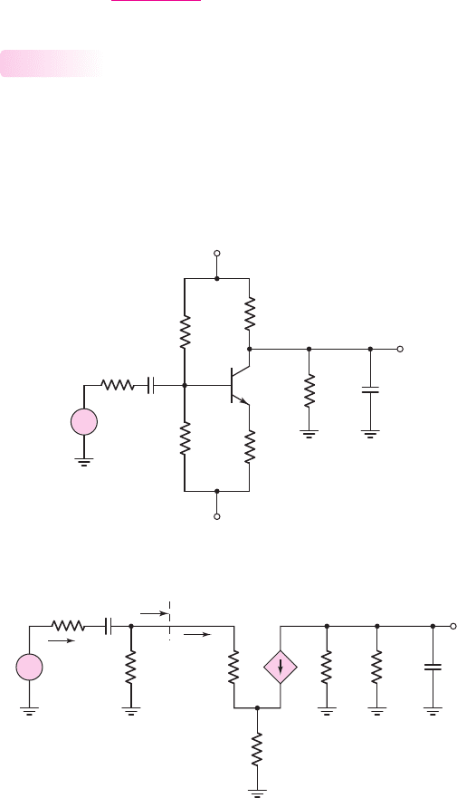
Coupling and Load Capacitors
A circuit with both a coupling capacitor and a load capacitor is shown in Fig-
ure 7.26(a). Since the values of the coupling capacitance and load capacitance differ
by orders of magnitude, the corner frequencies are far apart and can be treated
separately as discussed previously. The small-signal equivalent circuit is shown in
Figure 7.26(b), assuming the transistor small-signal resistance r
o
is infinite.
7.3.3
C
L
=
15 pF
C
C
=
10
m
F
R
2
=
5.7 kΩ
R
1
=
40 kΩ
R
S
= 0.1 kΩ
+5 V
–5 V
R
L
=
10 kΩ
R
E
=
0.5 kΩ
R
C
= 5 kΩ
v
O
v
i
+
–
(a)
(b)
C
C
=
10
m
F
R
C
=
5 kΩ
R
L
=
10 kΩ
R
S
= 0.1 kΩ
R
1
⎪⎪R
2
=
5 kΩ
g
m
V
p
+
–
V
p
r
p
V
i
V
o
I
i
I
b
R
i
R
E
= 0.5 kΩ
C
L
=
15 pF
+
–
Figure 7.26 (a) Circuit with both a coupling and a load capacitor and (b) small-signal
equivalent circuit
nea80644_ch07_469-558.qxd 06/13/2009 08:07 PM Page 493 F506 Hard disk:Desktop Folder:Rakesh:MHDQ134-07:

494 Part 1 Semiconductor Devices and Basic Applications
The Bode plot of the voltage gain magnitude is similar to that shown in Figure
7.11. The lower corner frequency f
L
is given by
f
L
=
1
2πτ
S
(7.47)
where
τ
S
is the time constant associated with the coupling capacitor C
C
, and the
upper corner frequency f
H
is given by
f
H
=
1
2πτ
P
(7.48)
where
τ
P
is the time constant associated with the load capacitor C
L
. It should be
emphasized that Equations (7.47) and (7.48) are valid only as long as the two corner
frequencies are far apart.
Using the small-signal equivalent circuit in Figure 7.26(b), we set the signal
source equal to zero to find the equivalent resistance associated with the coupling ca-
pacitor. The related time constant is
τ
S
= [R
S
+(R
1
R
2
R
i
)C
C
(7.49)
where
R
i
= r
π
+(1 +β)R
E
(7.50)
Similarly, the time constant related to C
L
is
τ
P
= (R
C
R
L
)C
L
(7.51)
Since the two corner frequencies are far apart, the gain will reach a maximum
value in the frequency range between f
L
and f
H
, which is the midband. We can calcu-
late the midband gain by assuming that the coupling capacitor is a short circuit and
the load capacitor is an open circuit.
Using the analysis techniques from the last chapter, we find the magnitude of the
midband gain as follows:
|
A
v
|
=
V
o
V
i
= g
m
r
π
(R
C
R
L
)
R
1
R
2
(R
1
R
2
) + R
i
1
[R
S
+(R
1
R
2
R
i
)]
(7.52)
EXAMPLE 7.6
Objective: Determine the midband gain, corner frequencies, and bandwidth of a
circuit containing both a coupling capacitor and a load capacitor.
Consider the circuit shownin Figure 7.26(a) with transistor parameters
V
BE
(on) =
0.7 V,
β = 100
, and
V
A
=∞
.
Solution: The dc analysis of this circuit yields a quiescent collector current of
I
CQ
= 0.99
mA. The small-signal parameters are
g
m
= 38.08
mA/V,
r
π
= 2.626 k
,
and
r
o
=∞
.
The input resistance R
i
is therefore
R
i
= r
π
+(1 +β)R
E
= 2.63 +(101)(0.5) = 53.1k
nea80644_ch07_469-558.qxd 06/13/2009 08:07 PM Page 494 F506 Hard disk:Desktop Folder:Rakesh:MHDQ134-07:

Chapter 7 Frequency Response 495
From Equation (7.52), the midband gain is
|A
v
|
max
=
V
o
V
i
max
= g
m
r
π
(R
C
R
L
)
R
1
R
2
(R
1
R
2
) + R
i
1
[R
S
+(R
1
R
2
R
i
)]
= (38.08)(2.626)(510)
405.7
(405.7) + 53.1
1
[0.1 + (405.753.1)]
or
A
v
max
= 6.14
The time constant
τ
S
is
τ
S
= (R
S
+ R
1
R
2
R
i
)C
C
= (0.1 ×10
3
+(5.7 ×10
3
)(40 × 10
3
)(53.1 × 10
3
))(10 × 10
−6
)
= 4.67 ×10
−2
s ⇒ 46.6ms
and the time constant
τ
P
is
τ
P
= (R
C
R
L
)C
L
= ((5 ×10
3
)(10 × 10
3
))(15 × 10
−12
) = 5 ×10
−8
s
or
τ
P
= 50 ns
The lower corner frequency is
f
L
=
1
2πτ
S
=
1
2π(46.6 ×10
−3
)
= 3.42 Hz
and the upper corner frequency is
f
H
=
1
2πτ
P
=
1
2π(50 ×10
−9
)
⇒ 3.18 MHz
Finally, the bandwidth is
f
BW
= f
H
− f
L
= 3.18 MHz − 3.4Hz
∼
=
3.18 MHz
Comment: The two corner frequencies differ by approximately six orders of magni-
tude; therefore, considering one capacitor at a time is a valid approach.
EXERCISE PROBLEM
Ex 7.6: Consider the circuit in Figure 7.26(a). The load resistance value is
changed to
R
L
= 5k
, and the capacitor values are changed to
C
L
= 5
pF and
C
C
= 5 μ
F. Other circuit and transistor parameters are the same as given in Ex-
ample 7.6. (a) Determine the new values of the collector current and small-signal
hybrid-pi parameters. (b) Determine the value of midband voltage gain. (c) Find
the corner frequencies of the circuit. (Ans. (a)
I
CQ
= 0.986
mA, (b)
A
v
=−4.60
,
(c)
f
L
= 6.82
Hz,
f
H
= 12.7
MHz)
A figure of merit for an amplifier is the gain–bandwidth product.Assuming the
corner frequencies are far apart, the bandwidth is
f
BW
= f
H
− f
L
∼
=
f
H
(7.53)
nea80644_ch07_469-558.qxd 06/13/2009 08:07 PM Page 495 F506 Hard disk:Desktop Folder:Rakesh:MHDQ134-07:
496 Part 1 Semiconductor Devices and Basic Applications
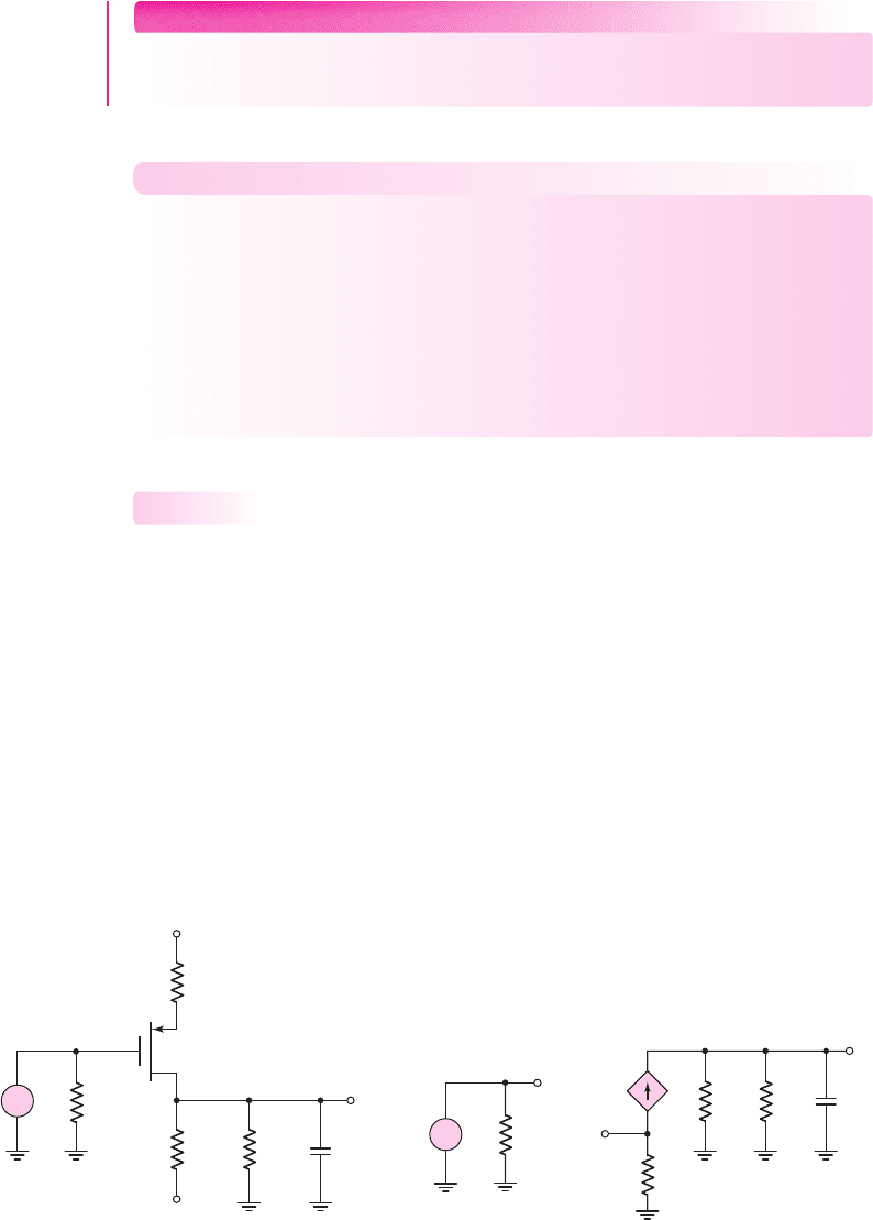
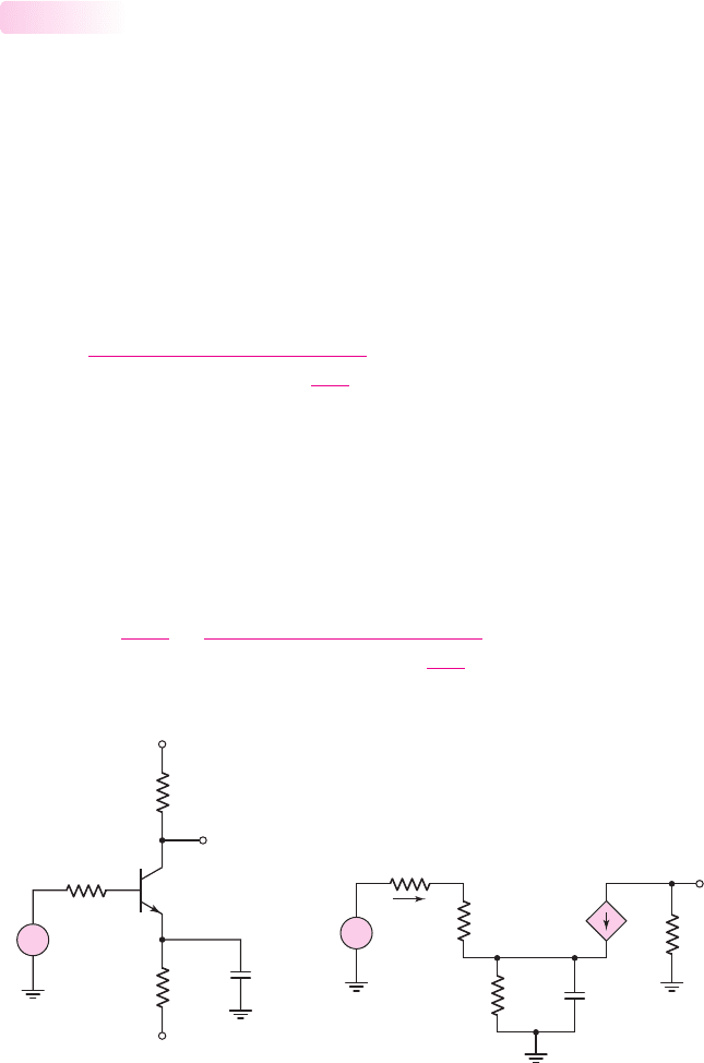
Figure 7.27
(a) Circuit with emitter bypass capacitor and (b) small-signal equivalent circuit
and the maximum gain is
|A
v
|
max
. The gain–bandwidth product is therefore
GB =|A
v
|
max
· f
H
(7.54)
Later we will show that, for a given load capacitance, this product is essentially a
constant. We will also describe how trade-offs must be made between gain and band-
width in amplifier design.
Bypass Capacitor Effects
In bipolar and FET discrete amplifiers, emitter and source bypass capacitors are often
included so that emitter and source resistors can be used to stabilize the Q-point with-
out sacrificing the small-signal gain. The bypass capacitors are assumed to act as
short circuits at the signal frequency. However, to guide us in choosing a bypass
capacitor, we must determine the circuit response in the frequency range where these
capacitors are neither open nor short circuits.
Figure 7.27(a) shows a common-emitter circuit with an emitter bypass capacitor.
The small-signal equivalent circuit is shown in Figure 7.27(b). We can find the small-
signal voltage gain as a function of frequency. Using the impedance reflection rule,
the small-signal input current is
I
b
=
V
i
R
S
+r
π
+(1 +β)
R
E
1
sC
E
(7.55)
The total impedance in the emitter is multiplied by the factor
(1 + β)
. The control
voltage is
V
π
= I
b
r
π
(7.56)
and the output voltage is
V
o
=−g
m
V
π
R
C
(7.57)
Combining equations produces the small-signal voltage gain, as follows:
A
v
(s) =
V
o
(s)
V
i
(s)
=
−g
m
r
π
R
C
R
S
+r
π
+(1 +β)
R
E
1
sC
E
(7.58)
7.3.4
(a)
(b)
V
+
V
–
R
S
v
O
v
i
C
E
R
C
R
E
+
–
V
i
R
S
C
E
V
o
R
C
r
p
R
E
+
–
V
p
g
m
V
p
I
b
+
–
nea80644_ch07_469-558.qxd 06/13/2009 08:07 PM Page 496 F506 Hard disk:Desktop Folder:Rakesh:MHDQ134-07:
Chapter 7 Frequency Response 497
Expanding the parallel combination of R
E
and 1/sC
E
and rearranging terms, we find
A
v
=
−g
m
r
π
R
C
[R
S
+r
π
+(1 +β)R
E
]
×
(1 + sR
E
C
E
)
1 +
sR
E
(R
S
+r
π
)C
E
[R
S
+r
π
+(1 +β)R
E
]
(7.59)
Equation (7.59) can be written in terms of time constants as
A
v
=
−g
m
r
π
R
C
[R
S
+r
π
+(1 +β)R
E
]
1 + sτ
A
1 + sτ
B
(7.60)
The form of this transfer function is somewhat different from what we have pre-
viously encountered in that we have both a zero and a pole.
The Bode plot of the voltage gain magnitude has two limiting horizontal
asymptotes. If we set
s = jω
, we can then consider the limit as
ω → 0
and the limit
as
ω →∞
. For
ω → 0
, C
E
acts as an open circuit; for
ω →∞
, C
E
acts as a short
circuit. From Equation (7.59), we have
|A
v
|
ω→0
=
g
m
r
π
R
C
[R
S
+r
π
+(1 +β)R
E
]
(7.61(a))
and
|A
v
|
ω→∞
=
g
m
r
π
R
C
R
S
+r
π
(7.61(b))
From these results, we see that for
ω → 0
, R
E
is included in the gain expression, and
for
ω →∞
, R
E
is not part of the gain expression, since it has been effectively
shorted out by C
E
.
If we assume that the time constants
τ
A
and
τ
B
in Equation (7.60) differ sub-
stantially in magnitude, then the corner frequency due to
τ
B
is
f
B
=
1
2πτ
B
(7.62(a))
and the corner frequency due to
τ
A
is
f
A
=
1
2πτ
A
(7.62(b))
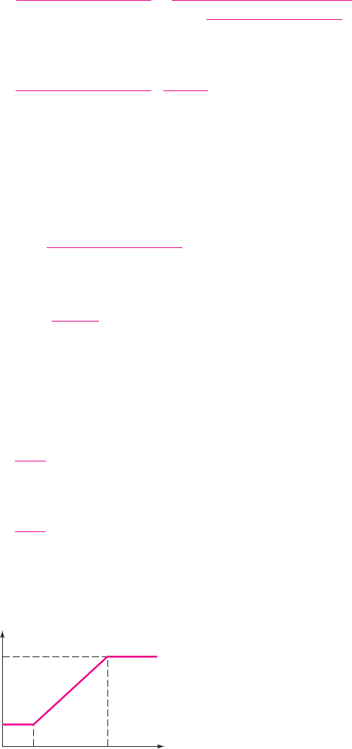
The resulting Bode plot of the voltage gain magnitude is shown in Figure 7.28.
f
A
f
B
f
|A
V
|
w
→ 0
|A
V
|
|A
V
|
w
→ ∞
Figure 7.28 Bode plot of the voltage gain magnitude for the circuit with an emitter bypass
capacitor
nea80644_ch07_469-558.qxd 06/13/2009 08:07 PM Page 497 F506 Hard disk:Desktop Folder:Rakesh:MHDQ134-07: