Neamen D. Microelectronics: Circuit Analysis and Design
Подождите немного. Документ загружается.

478 Part 1 Semiconductor Devices and Basic Applications
straight line with a slope of
−20
dB/decade, or
−6
dB/octave. The two asymptotes
meet at the frequency
f = 1/2πτ
P
, which is the corner, or 3 dB, frequency for this
circuit. Again, the actual magnitude of the transfer function at the corner frequency
differs from the maximum asymptotic value by 3 dB.
Again, the magnitude of the transfer function given by Equation (7.14) is for
the circuit shown in Figure 7.3. The parallel capacitor C
P
is a load, or parasitic,
capacitance. At low frequencies, C
P
acts as an open circuit, and the output voltage,
from a voltage divider, is
V
o
= [R
P
/(R
S
+ R
P
)]V
i
As the frequency increases, the magnitude of the impedance of C
P
decreases and ap-
proaches that of a short circuit, and the output voltage approaches zero. This circuit
is called a low-pass network, since the low-frequency signals are passed through to
the output.
The phase of the transfer function given by Equation (7.13) is
Phase =−
tan
−1
(2π f τ
P
)
(7.15)
The Bode plot of the phase is shown in Figure 7.9. The phase is −45 degrees at the
corner frequency and 0 degrees at the low-frequency asymptote, where C
P
is effec-
tively out of the circuit.
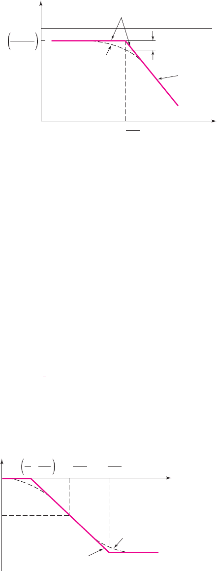
20 log
10
R
P
R
S
+ R
P
3 dB
Actual curve
Asymptotic
approximation
–20 dB/decade
or
–6 dB/octave
|T( j
f
)|
dB
0
f (log scale)
1
2pt
p
f =
Figure 7.8 Bode plot of the voltage transfer function magnitude for the circuit in Figure 7.3
Phase
0
–45°
–90°
1
10
1
⋅
Actual curve
Asymptotic
approximation
2
pt
p
1
2pt
p
10
2pt
p
f = f = f =
Figure 7.9 Bode plot of the voltage transfer function phase for the circuit in Figure 7.3
nea80644_ch07_469-558.qxd 06/13/2009 08:07 PM Page 478 F506 Hard disk:Desktop Folder:Rakesh:MHDQ134-07:

Chapter 7 Frequency Response 479
EXAMPLE 7.1
Objective: Determine the corner frequencies and maximum-magnitude asymptotes
of the Bode plots for a specified circuit.
For the circuits in Figures 7.2 and 7.3, the parameters are:
R
S
= 1k
,
R
P
= 10 k
,
C
S
= 1 μF
, and
C
P
= 3
pF.
Solution: (Figure 7.2) The time constant is
τ
S
= (R
S
+ R
P
)C
S
= (10
3
+10 ×10
3
)(10
−6
) = 1.1 ×10
−2
s ⇒ 11 ms
The corner frequency of the Bode plot shown in Figure 7.5 is then
f =
1
2πτ
S
=
1
(2π)(11 × 10
−3
)
= 14.5Hz
The maximum magnitude is
R
P
R
S
+ R
P
=
10
1 + 10
= 0.909
or
20 log
10
R
P
R
S
+ R
P
=−0.828 dB
Solution: (Figure 7.3) The time constant is
τ
P
= (R
S
R
P
)C
P
= (10
3
(10 × 10
3
))(3 × 10
−12
) ⇒ 2.73 ns
The corner frequency of the Bode plot in Figure 7.8 is then
f =
1
2πτ
P
=
1
(2π)(2.73 × 10
−9
)
⇒ 58.3 MHz
The maximum magnitude is the same as just calculated: 0.909 or
−0.828
dB.
Comment: Since the two capacitance values are substantially different, the two time
constants differ by orders of magnitude, which means that the two corner frequencies
also differ by orders of magnitude. Later in this text, we will take advantage of these
differences in our analysis of transistor circuits.
EXERCISE PROBLEM
Ex 7.1: (a) For the circuit shown in Figure 7.2, the parameters are
R
S
= 2k
and
R
P
= 8k
. (i) If the corner frequency is
f
L
= 50
Hz, determine the value of
C
S
.
(ii) Find the magnitude of the transfer function at
f = 20
Hz, 50 Hz, and 100 Hz.
(Ans. (i)
C
S
= 0.318 μF
; (ii) 0.297, 0.566, and 0.716)
(b) Consider the circuit shown in Figure 7.3 with parameters
R
S
= 4.7k
,
R
P
= 25 k
, and
C
P
= 120
pF. (i) Determine the corner frequency
f
H
. (ii) De-
termine the magnitude of the transfer function at
f = 0.2 f
H
,
f = f
H
, and
f = 8 f
H
. (Ans. (i)
f
H
= 335
kHz; (ii) 0.825, 0.595, 0.104)
nea80644_ch07_469-558.qxd 06/13/2009 08:07 PM Page 479 F506 Hard disk:Desktop Folder:Rakesh:MHDQ134-07:
480 Part 1 Semiconductor Devices and Basic Applications
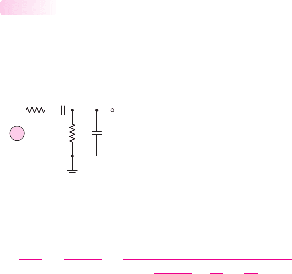
C
P
V
i
R
S
V
o
R
P
C
S
+
–
Figure 7.10 Circuit with both a series coupling and a parallel load capacitor
Short-Circuit and Open-Circuit Time Constants
The two circuits shown in Figures 7.2 and 7.3 each contain only one capacitor. The
circuit in Figure 7.10 is the same basic configuration but contains both capacitors.
Capacitor C
S
is the coupling capacitor and is in series with the input and output; ca-
pacitor C
P
is the load capacitor and is in parallel with the output and ground.
7.2.4
We can determine the voltage transfer function of this circuit by writing a KCL
equation at the output node. The result is
V
o
(s)
V
i
(s)
=
R
P
R
S
+ R
P
×
1
1 +
R
P
R
S
+ R
P
C
P
C
S
+
1
sτ
S
+sτ
P
(7.16)
where
τ
S
and
τ
P
are the same time constants as previously defined.
Although Equation (7.16) is the exact transfer function, it is awkward to deal
with in this form.
We have seen in the previous analysis, however, that C
S
affects the low-
frequency response and C
P
affects the high-frequency response. Further, if
C
P
C
S
and if R
S
and R
P
are of the same order of magnitude, then the corner frequencies of
the Bode plots created by C
S
and C
P
will differ by orders of magnitude. (We actually
encounter this situation in real circuits.) Consequently, when a circuit contains both
coupling and load capacitors, and when the values of the capacitors differ by orders
of magnitude, then we can determine the effect of each capacitor individually.
At low frequencies, we can treat the load capacitor C
P
as an open circuit. To find
the equivalent resistance seen by a capacitor, set all independent sources equal to
zero. Therefore, the effective resistance seen by C
S
is the series combination of R
S
and R
P
. The time constant associated with C
S
is
τ
S
= (R
S
+ R
P
)C
S
(7.17)
Since C
P
was made an open circuit,
τ
S
is called an open-circuit time constant. The
subscript S is associated with the coupling capacitor, or the capacitor in series with
the input and output signals.
At high frequencies, we can treat the coupling capacitor C
S
as a short circuit. The
effective resistance seen by C
P
is the parallel combination of R
S
and R
P
, and the as-
sociated time constant is
τ
P
= (R
S
R
P
)C
P
(7.18)
which is called the short-circuit time constant. The subscript P is associated with
the load capacitor, or the capacitor in parallel with the output and ground.
nea80644_ch07_469-558.qxd 06/13/2009 08:07 PM Page 480 F506 Hard disk:Desktop Folder:Rakesh:MHDQ134-07:
Chapter 7 Frequency Response 481
We can now define the corner frequencies of the Bode plot. The lower corner,
or 3 dB frequency, which is at the low end of the frequency scale, is a function of the
open-circuit time constant and is defined as
f
L
=
1
2πτ
S
(7.19(a))
The upper corner, or 3 dB, frequency, which is at the high end of the frequency
scale, is a function of the short-circuit time constant and is defined as
f
H
=
1
2πτ
P
(7.19(b))
The resulting Bode plot of the magnitude of the voltage transfer function for the cir-
cuit in Figure 7.9 is shown in Figure 7.11.
This Bode plot is for a passive circuit; the Bode plots for transistor amplifiers are
similar. The amplifier gain is constant over a wide frequency range, called the mid-
band. In this frequency range, all capacitance effects are negligible and can be
neglected in the gain calculations. At the high end of the frequency spectrum, the
gain drops as a result of the load capacitance and, as we will see later, the transistor
effects. At the low end of the frequency spectrum, the gain decreases because
coupling capacitors and bypass capacitors do not act as perfect short circuits.
The midband range, or bandwidth, is defined by the corner frequencies f
L
and
f
H
, as follows:
f
BW
= f
H
− f
L
(7.20(a))
Since
f
H
f
L
, as we have seen in our examples, the bandwidth is essentially given
by
f
BW
∼
=
f
H
(7.20(b))
T (max)
dB
f
L
f
H
V
o
V
i
f
Figure 7.11 Bode plot of the voltage transfer function magnitude for the circuit in
Figure 7.10
EXAMPLE 7.2
Objective: Determine the corner frequencies and bandwidth of a passive circuit
containing two capacitors.
Consider the circuit shown in Figure 7.10 with parameters
R
S
= 1k
,
R
P
=
10 k
,
C
S
= 1 μ
F, and
C
P
= 3
pF.
Solution: Since C
P
is less than C
S
by approximately six orders of magnitude, we can
treat the effect of each capacitor separately. The open-circuit time constant is
τ
S
= (R
S
+ R
P
)C
S
= (10
3
+10 ×10
3
)(10
−6
) = 1.1 ×10
−2
s
nea80644_ch07_469-558.qxd 06/13/2009 08:07 PM Page 481 F506 Hard disk:Desktop Folder:Rakesh:MHDQ134-07:
482 Part 1 Semiconductor Devices and Basic Applications
1.0
0.1
0.01
0
dB
3 dB
3 dB
Asymptotes
V
o
V
i
–20
0.1
1 10 100
f
H
= 58.3 MHz
f
L
= 14.5 Hz
f (Hz)
10
6
10
8
10
9
10
7
–40
–60
0.001
Figure 7.12 Bode plot of the magnitude of the voltage transfer function for the circuit in
Figure 7.10
and the short-circuit time constant is
τ
P
= (R
S
R
P
)C
P
= [10
3
(10 × 10
3
)](3 × 10
−12
) = 2.73 ×10
−9
s
The corner frequencies are then
f
L
=
1
2πτ
S
=
1
2π(1.1 ×10
−2
)
= 14.5Hz
and
f
H
=
1
2πτ
P
=
1
2π(2.73 ×10
−9
)
⇒ 58.3 MHz
Finally, the bandwidth is
f
BW
= f
H
− f
L
= 58.3 MHz − 14.5Hz
∼
=
58.3 MHz
Comment: The corner frequencies in this example are exactly the same as those de-
termined in Example 7.1. This occurred because the two corner frequencies are far
apart. The maximum magnitude of the voltage function is again
R
P
R
S
+ R
P
=
10
1 + 10
= 0.909 ⇒−0.828 dB
The Bode plot of the magnitude of the voltage transfer function is shown in Fig-
ure 7.12.
EXERCISE PROBLEM
Ex 7.2: The circuit shown in Figure 7.10 has parameters of
R
P
= 7.5k
and
C
P
= 80
pF. The midband gain is –2 dB and the lower corner frequency is
f
L
= 200
Hz (a) Determine
R
S
,
C
S
, and the upper corner frequency
f
H
. (b) De-
termine the open-circuit and short-circuit time constants. (Ans. (a)
R
S
= 1.94
k
,
C
S
= 0.0843 μ
F,
f
H
= 1.29
MHz; (b)
τ
S
= 0.796
ms,
τ
P
= 0.123 μ
s)
We will continue, in the following sections of the chapter, to use the concept of
open-circuit and short-circuit time constants to determine the corner frequencies of
the Bode plots of transistor circuits. An implicit assumption in this technique is that
coupling and load capacitance values differ by many orders of magnitude.
nea80644_ch07_469-558.qxd 06/13/2009 08:07 PM Page 482 F506 Hard disk:Desktop Folder:Rakesh:MHDQ134-07:
Chapter 7 Frequency Response 483
+
–
R
L
R
S
C
C
r
p
g
m
V
p
V
o
V
p
V
i
+
–
Figure 7.13 Figure for Exercise TYU 7.1
Test Your Understanding
TYU 7.1 For the equivalent circuit shown in Figure 7.13, the parameters are:
R
S
= 1k
,
r
π
= 2k
,
R
L
= 4k
,
g
m
= 50
mA/V, and
C
C
= 1 μ
F. (a) Determine
the expression for the circuit time constant. (b) Calculate the 3 dB frequency and
maximum gain asymptote. (c) Sketch the Bode plot of the transfer function magni-
tude. (Ans. (a)
τ = (r
π
+ R
S
)C
C
,
(b)
f
3dB
= 53.1
Hz,
|T ( jω)|
max
= 133
)
TYU 7.3 The parameters in the circuit shown in Figure 7.15 are
R
S
= 100
,
r
π
= 2.4k
,
g
m
= 50
mA/V,
R
L
= 10 k
,
C
C
= 5 μ
F, and
C
L
= 4
pF. (a) Find the
open-circuit and short-circuit time constants. (b) Calculate the midband voltage gain.
(c) Determine the lower and upper 3 dB frequencies. (Ans. (a)
τ
S
= 12.5
ms,
τ
P
= 0.04 μ
s; (b)
A
v
=−480
; (c)
f
L
= 12.7
Hz,
f
H
= 3.98
MHz)
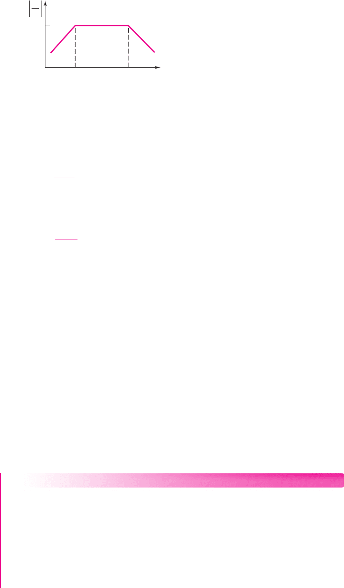
Time Response
Up to this point, we have been considering the steady-state sinusoidal frequency re-
sponse of circuits. In some cases, however, we may need to amplify nonsinusoidal
signals, such as square waves. This situation might occur if digital signals are to be
amplified. In these cases, we need to consider the time response of the output signals.
In addition, such signals as pulses or square waves may be used in testing the
frequency response of circuits.
7.2.5
V
p
r
p
V
o
V
i
R
L
C
L
+
–
g
m
V
p
+
–
R
S
Figure 7.14 Figure for Exercise TYU 7.2
V
p
r
p
V
o
V
i
R
L
C
L
+
–
g
m
V
p
+
–
R
S
C
C
Figure 7.15 Figure for Exercise TYU 7.3
TYU 7.2 The equivalent circuit in Figure 7.14 has circuit parameters
R
S
= 100
,
r
π
= 2.4
k
,
g
m
= 50
mA/V,
R
L
= 10 k
, and
C
L
= 2
pF. (a) Determine the
expression for and the value of the circuit time constant. (b) Calculate the 3 dB
frequency and the maximum voltage gain. (c) Sketch the Bode plot of the transfer
function magnitude. (Ans. (a)
τ = R
L
C
L
= 0.02 μ
s; (b)
f
3dB
= 7.96
MHz,
|
A
v
|
= 480)
nea80644_ch07_469-558.qxd 06/13/2009 08:07 PM Page 483 F506 Hard disk:Desktop Folder:Rakesh:MHDQ134-07:
484 Part 1 Semiconductor Devices and Basic Applications
+
–
R
S
R
P
V
i
(s)
V
o
(s)
Z
C
=
1
sC
P
Figure 7.18 Repeat of Figure 7.3 (load
capacitor circuit), but showing complex
s parameters
To gain some understanding, consider the circuit shown in Figure 7.16, which is
a repeat of Figure 7.2. As mentioned previously, the capacitor represents a coupling
capacitor. The transfer function was given in Equation (7.4) as
V
o
(s)
V
i
(s)
=
R
P
R
S
+ R
P
s(R
S
+ R
P
)C
S
1 + s(R
S
+ R
P
)C
S
= K
2
sτ
S
1 + sτ
S
(7.21)
where the time constant is
τ
S
= (R
S
+ R
P
)C
S
.
If the input voltage is a step function, then
V
i
(s) = 1/s
. The output voltage can
then be written as
V
o
(s) = K
2
τ
S
1 + sτ
S
= K
2
1
s + 1/τ
S
(7.22)
Taking the inverse Laplace transform, we find the output voltage time response as
v
o
(t) = K
2
e
−t/τ
S
(7.23)
If we are trying to amplify an input voltage pulse using a coupling capacitor, the
voltage applied to the amplifier (load) will begin to droop. In this case, we would
need to ensure that the time constant
τ
S
is large compared to the input pulse width T.
The output voltage versus time for a square wave input signal is shown in Figure 7.17.
A large time constant implies a large coupling capacitor.
If the cutoff frequency of the transfer function is
f
3-dB
= 1/2πτ
S
= 5
kHz, then
the time constant is
τ
S
= 3.18 μ
s. For a pulse width of
T = 0.1
μs, the output volt-
age will droop by only 0.314 percent at the end of the pulse.
Consider, now, the circuit shown in Figure 7.18, which is a repeat of Figure 7.3.
In this case, the capacitor C
P
may represent the input capacitance of an amplifier. The
transfer function was given in Equation (7.7) as
V
o
(s)
V
i
(s)
=
R
P
R
S
+ R
P
1
1 + s
(
R
P
R
S
)
C
P
= K
1
1
1 + sτ
P
(7.24)
where the time constant is
τ
P
= (R
P
R
S
)C
P
.
Again, if the input signal is a step function, then
V
i
(s) = 1/s
. The output voltage
can then be written as
V
o
(s) =
K
1
s
1
1 + sτ
P
=
K
1
s
1/τ
P
s + 1/τ
P
(7.25)
Taking the inverse Laplace transform, we find the output voltage time response as
v
o
(t) = K
1
(1 − e
−t/τ
P
)
(7.26)
If we are trying to amplify an input voltage pulse, we need to ensure that the time
constant
τ
P
is short compared to the pulse width T, so that the signal
v
O
(t)
reaches a
R
P
V
i
(s)
V
o
(s)
R
S
+
–
Z
C
=
1
sC
S
R
S
Figure 7.16 Repeat of
Figure 7.2 (coupling
capacitor circuit), but
showing complex s
parameters
v
O
(t)
0
T
t
Figure 7.17 Output response of circuit in
Figure 7.16 for a square-wave input signal
and for a large time constant
nea80644_ch07_469-558.qxd 06/13/2009 08:07 PM Page 484 F506 Hard disk:Desktop Folder:Rakesh:MHDQ134-07:
Chapter 7 Frequency Response 485
v
O
(t)
0
T
t
Figure 7.19 Output response
of circuit in Figure 7.18 for a
square-wave input signal and
for a short time constant
steady-state value. The output voltage is shown in Figure 7.19 for a square wave
input signal. A short time constant implies a very small capacitor C
P
as an input
capacitance to an amplifier.
In this case, if the cutoff frequency of the transfer function is f
3-dB
= 1/2πτ
P
=
10 MHz, then the time constant is
τ
P
= 15.9
ns.
Figure 7.20 summarizes the steady-state output responses for square wave input
signals of the two circuits we’ve just been considering. Figure 7.20(a) shows the
steady-state output response of the circuit in Figure 7.16 (coupling capacitor) for a
long time constant, and Figure 7.20(b) shows the steady-state output response of the
circuit in Figure 7.18 (load capacitor) for a short time constant.
T 2T 3T 4T
v
O
v
I
v
O
v
I
t
T 2T 3T 4T
v
O
v
I
v
I
v
O
t
(a)
(b)
Figure 7.20 Steady-state output response for a square-wave input response for
(a) circuit in Figure 7.16 (coupling capacitor) and a large time constant, and
(b) circuit in Figure 7.18 (load capacitor) and a short time constant
7.3 FREQUENCY RESPONSE: TRANSISTOR
AMPLIFIERS WITH CIRCUIT CAPACITORS
Objective: • Analyze the frequency response of transistor circuits
with capacitors.
In this section, we will analyze the basic single-stage amplifier that includes circuit
capacitors. Three types of capacitors will be considered: coupling capacitor, load ca-
pacitor, and bypass capacitor. In our hand analysis, we will consider each type of
capacitor individually and determine its frequency response. In the last part of this
section, we will consider the effect of multiple capacitors using a PSpice analysis.
The frequency response of multistage circuits will be considered in Chapter 12
when the stability of amplifiers is considered.
Coupling Capacitor Effects
Input Coupling Capacitor: Common-Emitter Circuit
Figure 7.21(a) shows a bipolar common-emitter circuit with a coupling capacitor.
Figure 7.21(b) shows the corresponding small-signal equivalent circuit, with the
transistor small-signal output resistance r
o
assumed to be infinite. This assumption
is valid since
r
o
R
C
and
r
o
R
E
in most cases. Initially, we will use a current–
voltage analysis to determine the frequency response of the circuit. Then, we will use
the equivalent time constant technique.
From the analysis in the previous section, we note that this circuit is a high-pass
network. At high frequencies, the capacitor C
C
acts as a short circuit, and the input
7.3.1
nea80644_ch07_469-558.qxd 06/13/2009 08:07 PM Page 485 F506 Hard disk:Desktop Folder:Rakesh:MHDQ134-07:
486 Part 1 Semiconductor Devices and Basic Applications
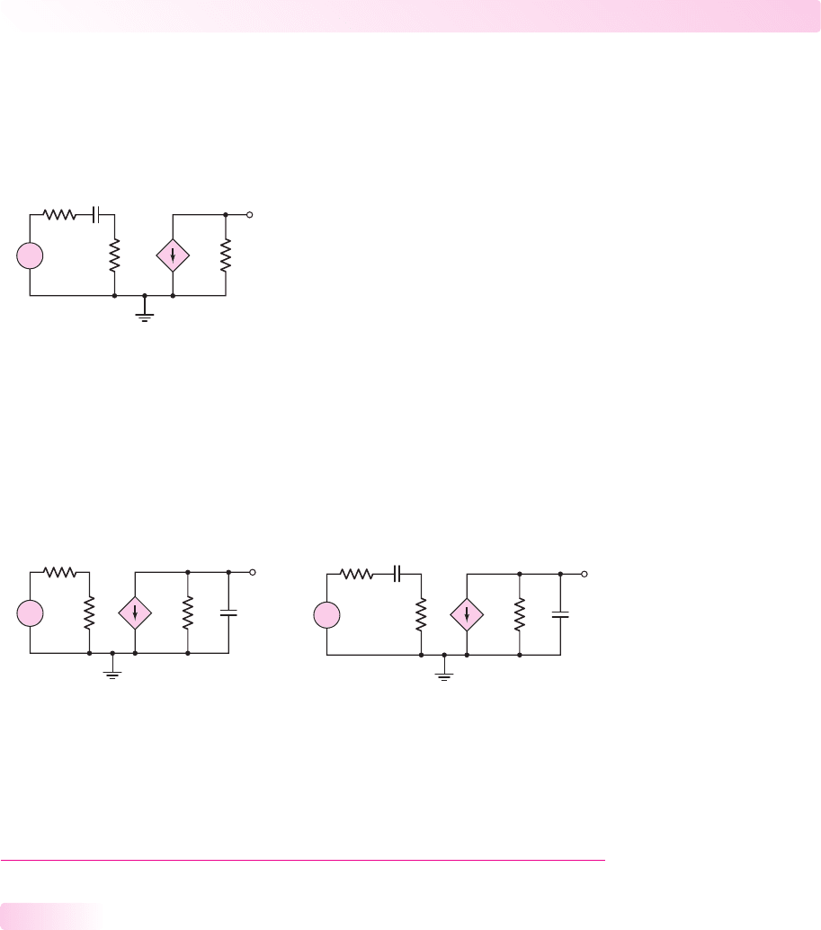
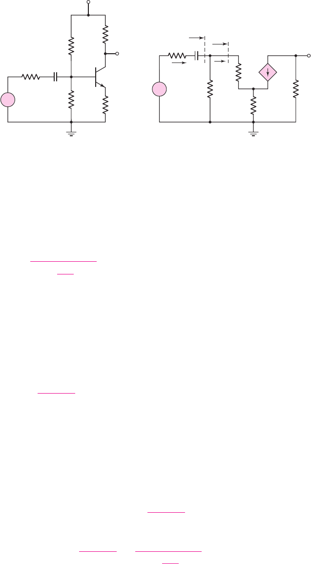
(a) (b)
v
i
R
Si
C
C
V
CC
v
O
R
C
R
E
R
1
R
2
+
–
V
i
R
Si
C
C
V
o
R
C
R
E
r
p
R
B
=
R
1⎪⎪
R
2
+
–
V
p
R
ib
g
m
V
p
I
b
I
i
R
i
+
–
Figure 7.21 (a) Common-emitter circuit with coupling capacitor and (b) small-signal
equivalent circuit
signal is coupled through the transistor to the output. At low frequencies, the imped-
ance of C
C
becomes large and the output approaches zero.
Current–Voltage Analysis: The input current can be written as
I
i
=
V
i
R
Si
+
1
sC
C
+ R
i
(7.27)
where the input resistance R
i
is given by
R
i
= R
B
[r
π
+(1 +β)R
E
] = R
B
R
ib
(7.28)
In writing Equation (7.28), we used the resistance reflection rule given in Chapter 6.
To determine the input resistance to the base of the transistor, we multiplied the emit-
ter resistance by the factor
(1 + β)
.
Using a current divider, we determine the base current to be
I
b
=
R
B
R
B
+ R
ib
I
i
(7.29)
and then
V
π
= I
b
r
π
(7.30)
The output voltage is given by
V
o
=−g
m
V
π
R
C
(7.31)
Combining Equations (7.27) through (7.31) produces
V
o
=−g
m
R
C
(I
b
r
π
) =−g
m
r
π
R
C
R
B
R
B
+ R
ib
I
i
=−g
m
r
π
R
C
R
B
R
B
+ R
ib
⎛
⎜
⎜
⎝
V
i
R
Si
+
1
sC
C
+ R
i
⎞
⎟
⎟
⎠
(7.32)
nea80644_ch07_469-558.qxd 06/13/2009 08:07 PM Page 486 F506 Hard disk:Desktop Folder:Rakesh:MHDQ134-07:

Chapter 7 Frequency Response 487
Therefore, the small-signal voltage gain is
A
v
(s) =
V
o
(s)
V
i
(s)
=−g
m
r
π
R
C
R
B
R
B
+ R
ib
sC
C
1 + s(R
Si
+ R
i
)C
C
(7.33)
which can be written in the form
A
v
(s) =
V
o
(s)
V
i
(s)
=
−g
m
r
π
R
C
(R
Si
+ R
i
)
R
B
R
B
+ R
ib
sτ
S
1 + sτ
S
(7.34)
where the time constant is
τ
S
= (R
Si
+ R
i
)C
C
(7.35)
The form of the voltage transfer function as given in Equation (7.34) is the same
as that of Equation (7.4), for the coupling capacitor circuit in Figure 7.2. The Bode
plot is therefore similar to that shown in Figure 7.5. The corner frequency is
f
L
=
1
2πτ
S
=
1
2π(R
Si
+ R
i
)C
C
(7.36)
and the maximum magnitude, in decibels, is
|A
v
(max)|
dB
= 20 log
10
g
m
r
π
R
C
R
Si
+ R
i
R
B
R
B
+ R
ib
(7.37)
EXAMPLE 7.3
Objective: Calculate the corner frequency and maximum gain of a bipolar common-
emitter circuit with a coupling capacitor.
For the circuit shown in Figure 7.21, the parameters are:
R
1
= 51.2k
,
R
2
= 9.6k
,
R
C
= 2k
,
R
E
= 0.4k
,
R
Si
= 0.1k
,
C
C
= 1 μ
F, and
V
CC
=
10 V. The transistor parameters are:
V
BE
(on) = 0.7
V,
β = 100
, and
V
A
=∞
.
Solution: From a dc analysis, the quiescent collector current is
I
CQ
= 1.81
mA. The
small-signal parameters are
g
m
= 69.6
mA/V and
r
π
= 1.44 k
.
The input resistance is
R
i
= R
1
R
2
[r
π
+(1 +β)R
E
]
= 51.2
9.6
[1.44 + (101)(0.4)] = 6.77 k
and the time constant is therefore
τ
S
= (R
Si
+ R
i
)C
C
= (0.1 ×10
3
+6.77 ×10
3
)(1 × 10
−6
) ⇒ 6.87 ms
The corner frequency is
f
L
=
1
2πτ
S
=
1
2π(6.87 ×10
−3
)
= 23.2Hz
Finally, the maximum voltage gain magnitude is
|A
v
|
max
=
g
m
r
π
R
C
(R
Si
+ R
i
)
R
B
R
B
+ R
ib
where
R
ib
= r
π
+(1 +β)R
E
= 1.44 +(101)(0.4) = 41.8k
nea80644_ch07_469-558.qxd 06/13/2009 08:07 PM Page 487 F506 Hard disk:Desktop Folder:Rakesh:MHDQ134-07: