Neamen D. Microelectronics: Circuit Analysis and Design
Подождите немного. Документ загружается.


468 Part 1 Semiconductor Devices and Basic Applications
6.82 For the circuit shown in Figure 6.43, use the circuit and transistor parame-
ters described in Example 6.9. (a) Calculate the average power dissipated
in the transistor,
R
E
, and
R
C
, for
v
s
= 0
. (b) Determine the maximum sig-
nal power that can be delivered to
R
L
. What are the signal powers dissipated
in
R
E
and
R
C
, and what is the average power dissipated in the transistor in
this case?
6.83 For the circuit shown in Figure 6.57, the transistor parameters are
β = 100
and
V
A
= 100
V, and the source resistor is
R
S
= 0
. Determine the maxi-
mum undistorted signal power that can be delivered to
R
L
if: (a)
R
L
=
1k
, and (b)
R
L
= 10 k
.
6.84 Consider the circuit shown in Figure 6.64 with parameters given in Exer-
cise TYU 6.14. (a) Calculate the average power dissipated in the transistor
and
R
C
, for
v
s
= 0
. (b) Determine the maximum undistorted signal power
that can be delivered to
R
L
, and the resulting average power dissipated in
the transistor and
R
C
.
COMPUTER SIMULATION PROBLEMS
6.85 (a) Using a computer simulation, verify the results of Exercise Ex 6.5.
(b) Repeat part (a) for Early voltages of (i)
V
A
= 100
V and (ii)
V
A
= 50
V.
6.86 (a) Using a computer simulation, verify the results of Exercise TYU 6.7.
(b) Repeat part (a) for an Early voltage of
V
A
= 50
V.
6.87 Using a computer simulation, verify the results of Example 6.10.
6.88 Using a computer simulation, verify the results of Exercise Ex 6.15 for the
multitransistor amplifier.
DESIGN PROBLEMS
[Note: Each design should be correlated with a computer simulation.]
*D6.89 Design a common-emitter amplifier with the general configuration shown in
Figure 6.39 except with a pnp transistor. The magnitude of the small-signal
voltage gain should be
|A
v
|=50
while driving a load
R
L
= 10
k
. Bias
the circuit at
±3.3
V.
*D6.90 Consider the circuit in Figure 6.20. Let
V
CC
= 5
V,
R
L
= 10
k
,
β = 120
,
and
V
A
=∞
. Design the circuit such that the small-signal current gain is
A
i
= 20
and such that the maximum undistorted swing in the output volt-
age is achieved.
*D6.91 A microphone puts out a peak voltage of 2 mV and has an output resistance
of 5 k
. Design an amplifier system to drive a 24
speaker, producing
0.5 W of signal power. Assume a current gain of
β = 50
for all available
transistors. Specify the current and power ratings of the transistors.
*D6.92 Redesign the two-stage amplifier in Figure 6.66 such that the voltage gain
of each stage is
A
v1
= A
v2
=−50
. Assume transistor current gains of
β
npn
= 150
and
β
pnp
= 110
. The total power dissipated in the circuit should
be limited to 25 mW.
nea80644_ch06_369-468.qxd 06/13/2009 08:21 PM Page 468 F506 Hard disk:Desktop Folder:Rakesh:MHDQ134-06:

Chapter
469
Thus far in our linear amplifier analyses, we have assumed that coupling capacitors
and bypass capacitors act as short circuits to the signal voltages and open circuits to
dc voltages. However, capacitors do not change instantaneously from a short circuit
to an open circuit as the frequency approaches zero. We have also assumed that tran-
sistors are ideal in that output signals respond instantaneously to input signals. How-
ever, there are internal capacitances in both the bipolar transistor and field-effect
transistor that affect the frequency response. The major goal of this chapter is to de-
termine the frequency response of amplifier circuits due to circuit capacitors and
transistor capacitances.
PREVIEW
In this chapter, we will:
• Discuss the general frequency response characteristics of amplifiers.
• Derive the system transfer functions of two simple R–C circuits, develop the
Bode plots for the magnitude and phase of the transfer functions, and become
familiar with sketching the Bode diagrams.
• Analyze the frequency response of transistor circuits with capacitors.
• Determine the frequency response of the bipolar transistor, and determine the
Miller effect and Miller capacitance.
• Determine the frequency response of the MOS transistor, and determine the
Miller effect and Miller capacitance.
• Determine the high-frequency response of basic transistor circuit configura-
tions including the cascode circuit.
• As an application, design a two-stage BJT amplifier with coupling capacitors
such that the 3 dB frequencies associated with each stage are equal.
7
7
Frequency Response
nea80644_ch07_469-558.qxd 06/13/2009 08:07 PM Page 469 F506 Hard disk:Desktop Folder:Rakesh:MHDQ134-07:
470 Part 1 Semiconductor Devices and Basic Applications
1
In many references, the gain is plotted as a function of the radian frequency
ω
. All curves in this chapter,
for consistency, will be plotted as a function of cyclical frequency f (Hz). We note that
ω = 2π
f
. The
amplifier gain is also plotted in terms of decibels (dB), where
|A|
dB
= 20 log
10
|A|
.
7.1 AMPLIFIER FREQUENCY RESPONSE
Objective: • Discuss the general frequency response characteristics
of amplifiers.
All amplifier gain factors are functions of signal frequency. These gain factors in-
clude voltage, current, transconductance, and transresistance. Up to this point, we
have assumed that the signal frequency is high enough that coupling and bypass ca-
pacitors can be treated as short circuits and, at the same time, we have assumed that
the signal frequency is low enough that parasitic, load, and transistor capacitances
can be treated as open circuits. In this chapter, we consider the amplifier response
over the entire frequency range.
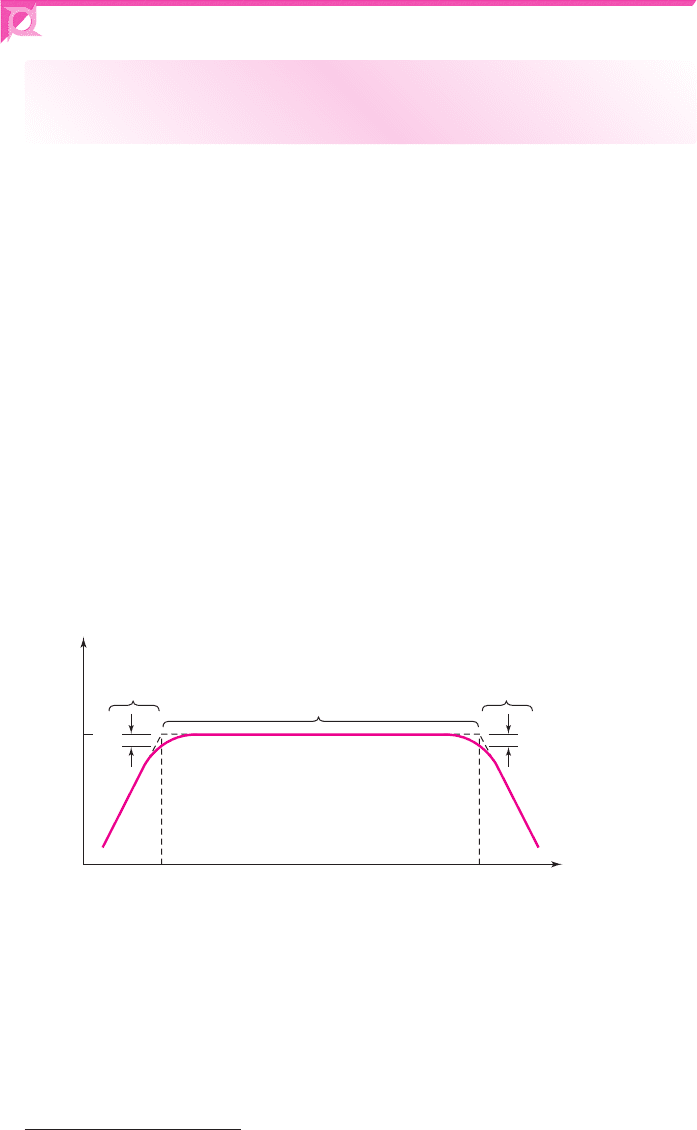
In general, an amplifier gain factor versus frequency will resemble that shown in
Figure 7.1.
1
Both the gain factor and frequency are plotted on logarithmic scales (the
gain factor in terms of decibels). Three frequency ranges, low, midband, and high,
are indicated. In the low-frequency range,
f < f
L
, the gain decreases as the fre-
quency decreases because of coupling and bypass capacitor effects. In the high-
frequency range,
f > f
H
, stray capacitance and transistor capacitance effects cause
the gain to decrease as the frequency increases. The midband range is the region
where coupling and bypass capacitors act as short circuits, and stray and transistor
capacitances act as open circuits. In this region, the gain is almost a constant. As we
will show, the gain at
f = f
L
and at
f = f
H
is 3 dB less than the maximum midband
gain. The bandwidth of the amplifier (in Hz) is defined as
f
BW
= f
H
− f
L
.
|A( jf )|
dB
|A
m
|
dB
f
L
f
H
f (Hz)
(lo
g
scale)
Low-frequency
range
Midband
High-frequency
range
3 dB 3 dB
Figure 7.1 Amplifier gain versus frequency
For an audio amplifier, for example, signal frequencies in the range of 20 Hz
<
f < 20
kHz need to be amplified equally so as to reproduce the sound as accu-
rately as possible. Therefore, in the design of a good audio amplifier, the frequency
f
L
must be designed to be less than 20 Hz and
f
H
must be designed to be greater than
20 kHz.
nea80644_ch07_469-558.qxd 06/13/2009 08:07 PM Page 470 F506 Hard disk:Desktop Folder:Rakesh:MHDQ134-07:

Chapter 7 Frequency Response 471
Equivalent Circuits
Each capacitor in a circuit is important at only one end of the frequency spectrum.
For this reason, we can develop specific equivalent circuits that apply to the low-
frequency range, to midband, and to the high-frequency range.
Midband Range
The equivalent circuits used for calculations in the midband range are the same as
those considered up to this point in the text. As already mentioned, the coupling and
bypass capacitors in this region are treated as short circuits. The stray and transistor
capacitances are treated as open circuits. In this frequency range, there are no capac-
itances in the equivalent circuit. These circuits are referred to as midband equivalent
circuits.
Low-Frequency Range
In this frequency range, we use a low-frequency equivalent circuit. In this region,
coupling and bypass capacitors must be included in the equivalent circuit and in the
amplification factor equations. The stray and transistor capacitances are treated as
open circuits. The mathematical expressions obtained for the amplification factor in
this frequency range must approach the midband results as f approaches the midband
frequency range, since in this limit the capacitors approach short-circuit conditions.
High-Frequency Range
In the high-frequency range, we use a high-frequency equivalent circuit. In this re-
gion, coupling and bypass capacitors are treated as short circuits. The transistor and
any parasitic or load capacitances must be taken into account in this equivalent
circuit. The mathematical expressions obtained for the amplification factor in this
frequency range must approach the midband results as f approaches the midband fre-
quency range, since in this limit the capacitors approach open-circuit conditions.
Frequency Response Analysis
Using the three equivalent circuits just considered rather than a complete circuit is an
approximation technique that produces useful hand-analysis results while avoiding
complex transfer functions. This technique is valid if there is a large separation
between f
L
and f
H
, that is
f
H
f
L
. This condition is satisfied in many electronic cir-
cuits that we will consider.
Computer simulations, such as PSpice, can take into account all capacitances
and can produce frequency response curves that are more accurate than the hand-
analysis results. However, the computer results do not provide any physical insight
into a particular result and hence do not provide any suggestions as to design changes
that can be made to improve a particular frequency response. A hand analysis can
provide insight into the “whys and wherefores” of a particular response. This basic
understanding can then lead to a better circuit design.
In the next section, we introduce two simple circuits to begin our frequency
analysis study. We initially derive the mathematical expressions relating output volt-
age to input voltage (transfer function) as a function of signal frequency. From these
functions, we can develop the response curves. The two frequency response curves
give the magnitude of the transfer function versus frequency and the phase of the
7.1.2
7.1.1
nea80644_ch07_469-558.qxd 06/13/2009 08:07 PM Page 471 F506 Hard disk:Desktop Folder:Rakesh:MHDQ134-07:

472 Part 1 Semiconductor Devices and Basic Applications
transfer function versus frequency. The phase response relates the phase of the output
signal to the phase of the input signal.
We will then develop a technique by which we can easily sketch the frequency
response curves without resorting to a full analysis of the transfer function. This sim-
plified approach will lead to a general understanding of the frequency response of
electronic circuits. We will then rely on a computer simulation to provide more
detailed calculations when required.
7.2 SYSTEM TRANSFER FUNCTIONS
Objective: • Derive the system transfer functions of two circuits, de-
velop the Bode diagrams of the magnitude and phase of the transfer
functions, and become familiar with sketching the Bode diagrams.
The frequency response of a circuit is usually determined by using the complex fre-
quency s. Each capacitor is represented by its complex impedance, 1/sC, and each
inductor is represented by its complex impedance, sL. The circuit equations are then
formulated in the usual way. Using the complex frequency, the mathematical expres-
sions obtained for voltage gain, current gain, input impedance, or output impedance
are ratios of polynomials in s.
We will be concerned in many cases with system transfer functions. These will
be in the form of ratios of, for example, output voltage to input voltage (voltage
transfer function) or output current to input voltage (transconductance function). The
four general transfer functions are listed in Table 7.1.
Once a transfer function is found, we can find the result of a steady-state sinu-
soidal excitation by setting
s = jω = j2π f
. The ratio of polynomials in s then
reduces to a complex number for each frequency f. The complex number can be
reduced to a magnitude and a phase.
Table 7.1 Transfer functions of the complex
frequency s
Name of function Expression
Voltage transfer function T(s) = V
o
(s)/V
i
(s)
Current transfer function I
o
(s)/I
i
(s)
Transresistance function V
o
(s)/I
i
(s)
Transconductance function I
o
(s)/V
i
(s)
s-Domain Analysis
In general, a transfer function in the s-domain can be expressed in the form
T (s) = K
(s − z
1
)(s − z
2
) ···(s − z
m
)
(s − p
1
)(s − p
2
) ···(s − p
n
)
(7.1)
where K is a constant,
z
1
, z
2
,...,z
m
are the transfer function “zeros,” and
p
1
, p
2
,...,p
n
are the transfer function “poles.” When the complex frequency is
7.2.1
nea80644_ch07_469-558.qxd 06/13/2009 08:07 PM Page 472 F506 Hard disk:Desktop Folder:Rakesh:MHDQ134-07:
Chapter 7 Frequency Response 473
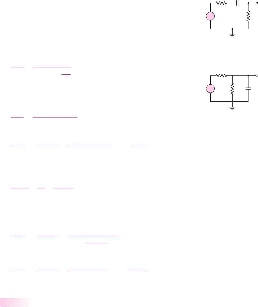
C
S
R
P
V
i
R
S
V
o
+
–
Figure 7.2 Series coupling
capacitor circuit
equal to a zero,
s = z
i
, the transfer function is zero; when the complex frequency is
equal to a pole,
s = p
i
, the transfer function diverges and becomes infinite. The
transfer function can be evaluated for physical frequencies by replacing s with
jω
. In
general, the resulting transfer function
T ( jω)
is a complex function, that is, its mag-
nitude and phase are both functions of frequency. These topics are usually discussed
in a basic circuit analysis course.
To introduce the frequency response analysis of transistor circuits, we will
examine the circuits shown in Figures 7.2 and 7.3. The voltage transfer function for
the circuit in Figure 7.2 can be expressed in a voltage divider format, as follows:
V
o
(s)
V
i
(s)
=
R
P
R
S
+ R
P
+
1
sC
S
(7.2)
The elements R
S
and C
S
are in series between the input and output signals, and the
element R
P
is in parallel with the output signal. Equation (7.2) can be written in the
form
V
o
(s)
V
i
(s)
=
sR
P
C
S
1 + s(R
S
+ R
P
)C
S
(7.3)
which can be rearranged and written as
V
o
(s)
V
i
(s)
=
R
P
R
S
+ R
P
s(R
S
+ R
P
)C
S
1 + s(R
S
+ R
P
)C
S
= K
sτ
s
1 + sτ
s
(7.4)
where
τ
S
is a time constant and is given by
τ
S
= (R
S
+ R
P
)C
S
.
Writing a Kirchhoff current law (KCL) equation at the output node, we can de-
termine the voltage transfer function for the circuit shown in Figure 7.3, as follows:
V
o
− V
i
R
S
+
V
o
R
P
+
V
o
(1/sC
P
)
= 0
(7.5)
In this case, the element R
S
is in series between the input and output signals, and the
elements R
P
and C
P
are in parallel with the output signal. Rearranging the terms in
Equation (7.5) produces
V
o
(s)
V
i
(s)
=
R
P
R
S
+ R
P
⎡
⎢
⎢
⎣
1
1 + s
R
S
R
P
R
S
+ R
P
C
P
⎤
⎥
⎥
⎦
(7.6)
or
V
o
(s)
V
i
(s)
=
R
P
R
S
+ R
P
1
1 + s(R
S
R
P
)C
P
= K
1
1 + sτ
P
(7.7)
where
τ
P
is also a time constant and is given by
τ
P
= (R
S
R
P
)C
P
.
First-Order Functions
In our hand analysis of transistor circuits in this chapter, we will, in general, limit
ourselves to the consideration of only one capacitance at a time. We will therefore
be dealing with first-order transfer functions that, in most cases, will have the
general form of either Equation (7.4) or (7.7). This simplified analysis will allow us
to present the frequency responses of specific capacitances and of the transistors
7.2.2
C
P
V
i
R
S
V
o
R
P
+
–
Figure 7.3 Parallel load
capacitor circuit
nea80644_ch07_469-558.qxd 06/13/2009 08:07 PM Page 473 F506 Hard disk:Desktop Folder:Rakesh:MHDQ134-07:

474 Part 1 Semiconductor Devices and Basic Applications
themselves. We will then compare our hand analysis results with more rigorous so-
lutions, using a computer simulation.
Bode Plots
A simplified technique for obtaining approximate plots of the magnitude and phase
of a transfer function, given the poles and zeros or the equivalent time constants, was
developed by H. Bode, and the resulting diagrams are called Bode plots.
Qualitative Discussion: Initially, we will consider the magnitude of the voltage
transfer function versus frequency. Before we delve into the mathematics, we can
qualitatively determine the general characteristics of this plot. The capacitor C
S
in
Figure 7.2 is in series between the input and output terminals. This capacitor then
behaves as a coupling capacitor.
In the limit of zero frequency (the input signal is a constant dc voltage), the im-
pedance of the capacitor is infinite (an open circuit). In this case, then, the input sig-
nal does not get coupled to the output terminal so the output voltage is zero. In this
case, the magnitude of the voltage transfer function is zero.
In the limit of a very high frequency, the impedance of the capacitor becomes
very small (approaching a short circuit). In this situation, the magnitude of the
output voltage reaches a constant value given by a voltage divider, or
V
o
=
[R
P
/(R
P
+ R
S
)] · V
i
.
We therefore expect the magnitude of the transfer function to start at zero for
zero frequency, increase for increasing frequency, and reach a constant value at a rel-
atively high frequency.
Bode Plot for Figure 7.2
Mathematical Derivation: For the transfer function in Equation (7.4), correspond-
ing to the circuit in Figure 7.2, if we replace s by
jω
and define a time constant
τ
s
as
τ
s
= (R
S
+ R
P
)C
S
, we obtain
T ( jω) =
V
o
( jω)
V
i
( jω)
=
R
P
R
S
+ R
P
jωτ
S
1 + jωτ
S
(7.8)
The magnitude of Equation (7.8) is
|
T ( jω)
|
=
R
P
R
S
+ R
P
⎡
⎣
ωτ
S
1 + ω
2
τ
2
S
⎤
⎦
(7.9(a))
or
|
T ( jf)
|
=
R
P
R
S
+ R
P
2π f τ
S
1 + (2π f τ
S
)
2
(7.9(b))
We can develop the Bode plot of the gain magnitude versus frequency. We may
note that
|T ( jf)|
dB
= 20 log
10
|T ( jf)|
. From Equation (7.9(b)), we can write
|
T ( jf)
|
dB
= 20 log
10
R
P
R
S
+ R
P
·
2π f τ
S
1 + (2π f τ
S
)
2
(7.10(a))
7.2.3
nea80644_ch07_469-558.qxd 06/13/2009 08:07 PM Page 474 F506 Hard disk:Desktop Folder:Rakesh:MHDQ134-07:
Chapter 7 Frequency Response 475
or
|
T ( jf)
|
dB
= 20 log
10
R
P
R
S
+ R
P
+20 log
10
(2π f τ
S
)
−20 log
10
1 + (2π f τ
S
)
2
(7.10(b))
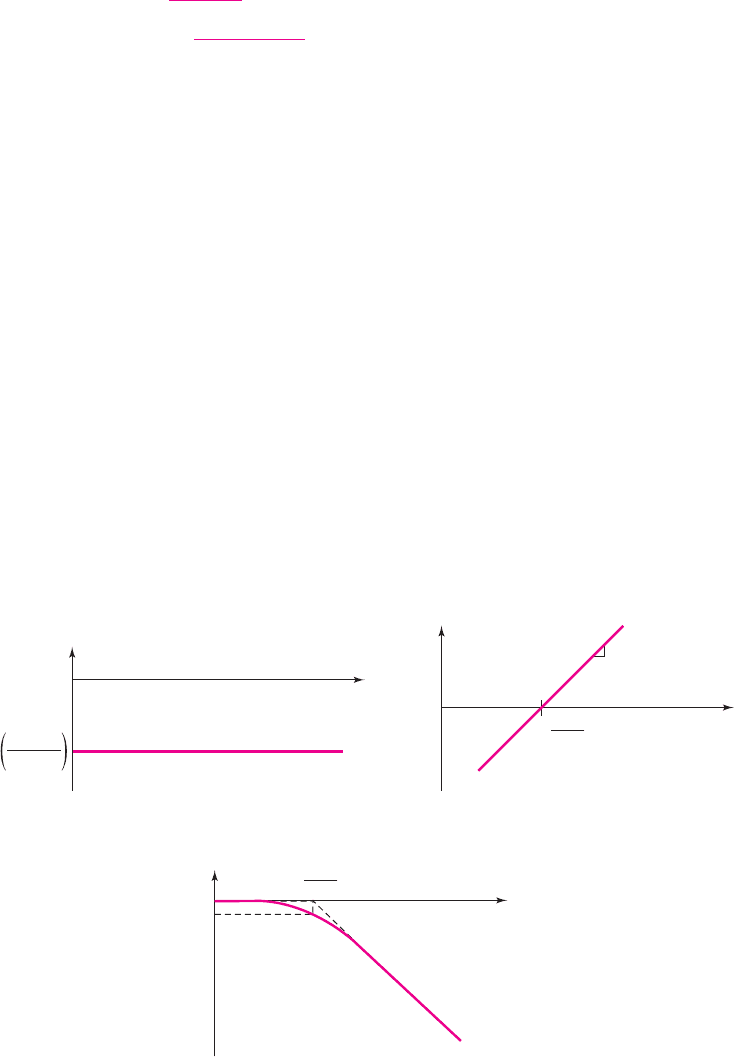
We can plot each term of Equation (7.10(b)) and then combine the three plots to form
the final Bode plot of the gain magnitude.
Figure 7.4(a) is the plot of the first term of equation (7.10(b)), which is just a
constant independent of frequency. We may note that, since
[R
P
/(R
S
+ R
P
)]
is less
than unity, the dB value is less than zero.
Figure 7.4(b) is the plot of the second term of Equation (7.10(b)). When
f = 1/2πτ
S
, we have 20log
10
(1) = 0
. The slopes in Bode plot magnitudes are
described in units of either dB/octave or dB/decade. An octave means that frequency
is increased by a factor of two, and a decade implies that the frequency is increased
by a factor of 10. The value of the function 20 log
10
(2π f τ
S
)
increases by a factor of
6.02
∼
=
6
dB for every factor of 2 increase in frequency, and the value of the function
increases by a factor of 20 dB for every factor of 10 increase in frequency. Hence, we
can consider a slope of 6 dB/octave or 20 dB/decade.
Figure 7.4(c) is the plot of the third term in Equation (7.10(b)). For
f 1/2πτ
S
, the value of the function is essentially 0 dB and when
f = 1/2πτ
S
,
the value is
−3
dB. For
f 1/2πτ
S
, the function becomes
−20 log
10
(2π f τ
S
)
,so
the slope becomes
−6
dB/octave or
−20
dB/decade. A straight-line projection of this
slope passes through 0 dB at
f = 1/2πτ
S
. We can then approximate the Bode plot
for this term by two straight line asymptotes intersecting at 0 dB and
f = 1/2πτ
S
.
This particular frequency is known as a break-point frequency, corner frequency,
or
−3
dB frequency.
–6 dB/octave
or
–20 dB/decade
dB
–3 dB
0
f (log scale)
1
2pt
S
f =
(c)
6 dB/octave
or
20 dB/decade
dB
0
f (log scale)
1
2pt
S
f =
(b)
dB
0
f (log scale)
(a)
20 log
10
R
P
R
P
+ R
S
Figure 7.4 Plots of (a) the first term, (b) the second term, and (c) the third term of
Equation (7.10(b))
nea80644_ch07_469-558.qxd 06/13/2009 08:07 PM Page 475 F506 Hard disk:Desktop Folder:Rakesh:MHDQ134-07:
476 Part 1 Semiconductor Devices and Basic Applications
20 log
10
R
P
R
S
+ R
P
|T( j
f
)|
dB
3 dB
0
Actual curve
Asymptotic
approximation
+6 dB/octave
or
+20 dB/decade
f (log scale)
1
2pt
s
f =
Figure 7.5 Bode plot of the voltage transfer function magnitude
for the circuit in Figure 7.2
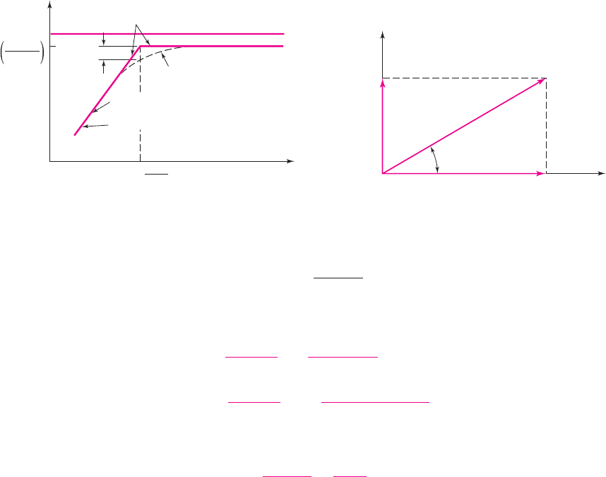
The complete Bode plot of Equation (7.10(b)) is shown in Figure 7.5. For
f 1/2πτ
S
, the second and third terms of Equation (7.10(b)) cancel, and for
f 1/2πτ
S
, the large negative dB value from Figure 7.4(b) dominates.
The transfer function given by Equation (7.9) is for the circuit shown in Fig-
ure 7.2. The series capacitor C
S
is a coupling capacitor between the input and output
signals. At a high enough frequency, capacitor C
S
acts as a short circuit, and the out-
put voltage, from a voltage divider, is
V
o
= [R
P
/(R
S
+ R
P
)]V
i
For very low frequencies, the impedance of C
S
approaches that of an open circuit,
and the output voltage approaches zero. This circuit is called a high-pass network
since the high-frequency signals are passed through to the output. We can now un-
derstand the form of the Bode plot shown in Figure 7.5.
Imaginary
part
Real part
A
B
K
q
Figure 7.6 Relation between rectangular and polar
forms of a complex number
The Bode plot of the phase function can be easily developed by recalling the re-
lation between the rectangular and polar form of a complex number. We can write
A + jB = Ke
jθ
, where
K =
√
A
2
+ B
2
and
θ = tan
−1
(B/A)
. This relationship is
shown in Figure 7.6.
For the function given in Equation (7.8), we can write the function in the form
T ( jf) =
R
P
R
S
+ R
P
·
j2π f τ
S
1 + j2π f τ
S
=
R
P
R
S
+ R
P
e
jθ
1
[|j2π f τ
S
|e
jθ
2
]
[|1 + j2π f τ
S
|e
jθ
3
]
(7.11(a))
or
T ( jf) =
K
1
e
jθ
1
K
2
e
jθ
2
K
3
e
jθ
3
=
K
1
K
2
K
3
e
j(θ
1
+θ
2
−θ
3
)
(7.11(b))
The net phase of the function
T ( jf)
is then
θ = θ
1
+θ
2
−θ
3
.
Since the first term,
[R
P
/(R
S
+ R
P
)]
, is a positive real quantity, the phase is
θ
1
= 0
. The second term,
( j2π f τ
S
)
, is purely imaginary so that the phase is
θ
2
= 90
◦
. The third term is complex so that its phase is
θ
3
= tan
−1
(2π f τ
S
)
. The net
phase of the function is now
θ = 90 − tan
−1
(2π f τ
S
)
(7.12)
nea80644_ch07_469-558.qxd 06/13/2009 08:07 PM Page 476 F506 Hard disk:Desktop Folder:Rakesh:MHDQ134-07:
Chapter 7 Frequency Response 477
For the limiting case of
f → 0
, we have
tan
−1
(0) = 0
, and for
f →∞
,we
have
tan
−1
(∞) = 90
◦
. At the corner frequency of
f = 1/(2πτ
S
)
, the phase is
tan
−1
(1) = 45
◦
. The Bode plot of the phase of the function given in Equation (7.11(a))
is given in Figure 7.7. The actual plot as well as an asymptotic approximation is
shown. The phase is especially important in feedback circuits since this can influence
stability. We will see this effect in Chapter 12.
Bode Plot for Figure 7.3
Qualitative Discussion: Again, we will initially consider the magnitude of the volt-
age function versus frequency. The capacitor C
P
in Figure 7.3 is in parallel with the
output and then behaves as a load capacitor on the output of a circuit, or may repre-
sent the input capacitance of a follow-on amplifier stage.
In the limit of zero frequency (the input signal is a constant dc voltage), the
impedance of the capacitor is infinite (an open circuit). In this case the output signal
is a constant value given by a voltage divider, or
V
o
= [R
P
/(R
P
+ R
S
)] · V
i
.
In the limit of a very high frequency, the impedance of the capacitor becomes
very small (approaching a short circuit). In this situation, the output voltage will be
zero, or the magnitude of the voltage transfer function will be zero.
We therefore expect the magnitude of the transfer function to start at a constant
value for zero and low frequencies, and then decrease toward zero at high
frequencies.
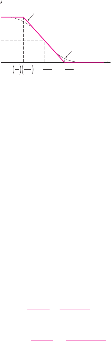
Mathematical Derivation: The transfer function given by Equation (7.7) is for the
circuit that was shown in Figure 7.3. If we replace s by
s = jω = j2π f
and define a
time constant
τ
P
as
τ
P
= (R
S
R
P
)C
P
, then the transfer function is
T ( jf) =
R
P
R
S
+ R
P
1
1 + j2π f τ
P
(7.13)
The magnitude of Equation (7.13) is
|T ( jf)|=
R
P
R
S
+ R
P
·
1
1 + (2π f τ
P
)
2
(7.14)
A Bode plot of this magnitude expression is shown in Figure 7.8. The low-
frequency asymptote is a horizontal line, and the high-frequency asymptote is a
Phase
0
45°
90°
1
10
1110
Actual curve
Asymptotic
approximation
2pt
S
2pt
S
2pt
S
f (log scale)
f = f = f =
Figure 7.7 Bode plot of the voltage transfer function
phase for the circuit in Figure 7.2
nea80644_ch07_469-558.qxd 06/13/2009 08:07 PM Page 477 F506 Hard disk:Desktop Folder:Rakesh:MHDQ134-07: