Neamen D. Microelectronics: Circuit Analysis and Design
Подождите немного. Документ загружается.

528 Part 1 Semiconductor Devices and Basic Applications
EXERCISE PROBLEM
*Ex 7.14: Consider the common-base circuit in Figure 7.64. The transistor para-
meters are
β = 100
,
V
BE
(on) = 0.7
V,
V
A
=∞
,
C
π
= 24
pF, and
C
μ
= 3
pF. (a)
Determine the upper 3 dB frequencies corresponding to the input and output por-
tions of the equivalent circuit. (b) Calculate the small-signal midband voltage
gain. (Ans. (a)
f
Hπ
= 223
MHz,
f
Hμ
= 58.3
MHz, (b)
A
v
= 0.869
)
+
–
10 V
+
–
10 V
C
B
→ ∞
C
C1
→ ∞
R
S
= 1 kΩ
R
E
=
10 kΩ
R
C
=
10 kΩ
R
B
=
100 kΩ
v
i
R
L
=
1 kΩ
v
o
C
C2
→ ∞
+
–
+
–
Figure 7.64 Figure for Exercise Ex 7.14
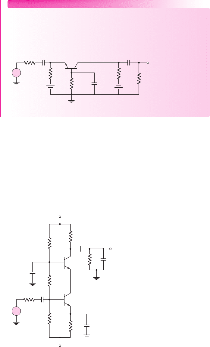
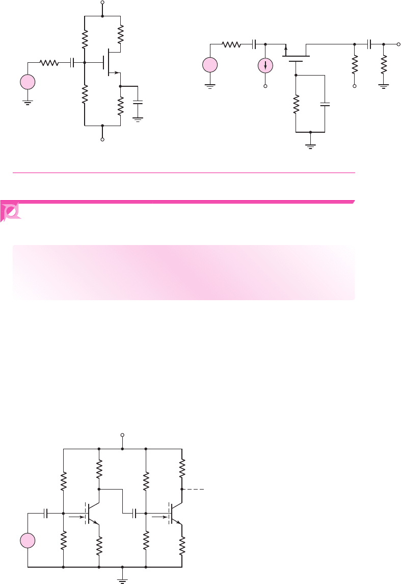
Cascode Circuit
The cascode circuit, as shown in Figure 7.65, combines the advantages of the common-
emitter and common-base circuits. The input signal is applied to the common-emitter
circuit (Q
1
), and the output signal from the common emitter is fed into the common-
base circuit (Q
2
). The input impedance to the common-emitter circuit (Q
1
) is rela-
tively large, and the load resistance seen by Q
1
is the input impedance to the emitter
of Q
2
and is fairly small. The low output resistance seen by Q
1
reduces the Miller
multiplication factor on
C
μ1
and therefore extends the bandwidth of the circuit.
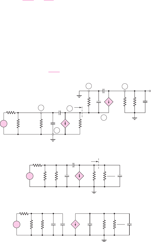
Figure 7.66(a) shows the high-frequency small-signal equivalent circuit. The
coupling and bypass capacitors are equivalent to short circuits, and resistance
r
o
for
Q
2
is assumed to be infinite.
v
O
R
S
C
C1
R
1
R
2
R
C
R
L
R
3
R
E
C
L
V
+
V
–
v
i
+
–
C
C2
C
E
C
B
Q
2
Q
1
+
–
Figure 7.65 Cascode circuit
nea80644_ch07_469-558.qxd 06/13/2009 08:07 PM Page 528 F506 Hard disk:Desktop Folder:Rakesh:MHDQ134-07:
Chapter 7 Frequency Response 529
The input impedance to the emitter of Q
2
is
Z
ie2
. From Equation (7.113) in our
previous analysis, we have
Z
ie2
=
r
π2
1 + β
1
sC
π2
(7.116)
The input portion of the small-signal equivalent circuit can be transformed to that
shown in Figure 7.66(b). The input impedance
Z
ie2
is again shown.
The input portion of the circuit shown in Figure 7.66(b) can be transformed to
that given in Figure 7.66(c), which shows the Miller capacitance. The Miller capaci-
tance
C
M1
is included in the input, and capacitance
C
μ1
is included in the output
portion of the Q
1
model. The possibility of including
C
μ
in the output circuit was
discussed previously in Section 7.4.4.
In the center of this equivalent circuit,
r
o1
is in parallel with
r
μ2
/(1 + β)
. Since
r
o1
is usually large, it can be approximated as an open circuit. The Miller capacitance
is then
C
M1
= C
μ1
1 + g
m1
r
π2
1 + β
(7.117)
r
p
1
C
p
1
C
m
1
g
m1
V
p
1
r
o1
+
–
V
p
1
+
–
V
p
2
R
B1
C
p
2
C
M1
V
i
R
S
1 +
b
r
p
2
(c)
+
–
r
p
1
C
p
1
C
m
1
C
p
2
g
m1
V
p
1
r
o1
+
–
V
p
1
+
–
V
p
2
R
B1
V
i
R
S
Z
ie2
1 +
b
r
p
2
(b)
+
–
R
L
C
p
2
C
L
R
S
g
m2
V
p
2
g
m1
V
p
1
V
o
r
p
2
Z
ie2
r
o1
R
C
C
m
2
V
i
C
p
1
C
m
1
r
p
1
V
p
2
+
–
V
p
1
+
–
R
B1
=
R
2
⎪⎪ R
3
B
1
C
1
B
2
C
2
E
2
E
1
(a)
+
–
Figure 7.66 (a) High-frequency equivalent circuit of cascode configuration, (b) rearranged
high-frequency equivalent circuit, and (c) variation of the high-frequency circuit, including
the Miller capacitance
nea80644_ch07_469-558.qxd 06/13/2009 08:07 PM Page 529 F506 Hard disk:Desktop Folder:Rakesh:MHDQ134-07:

530 Part 1 Semiconductor Devices and Basic Applications
Transistors Q
1
and Q
2
are biased with essentially the same current; therefore,
r
π1
∼
=
r
π2
and g
m1
∼
=
g
m2
Then
g
m1
r
π2
= β
which yields
C
M1
∼
=
2 C
μ1
(7.118)
Equation (7.118) shows that this cascode circuit greatly reduces the Miller multipli-
cation factor.
The time constant related to
C
π2
involves resistance
r
π2
/(1 + β)
. Since this re-
sistance is small, the time constant is small, and the corner frequency related to
C
π2
is very large. We can therefore neglect the effects of
C
μ1
and
C
π2
in the center por-
tion of the circuit.
The time constant for the input portion of the circuit is
τ
Pπ
= [R
S
R
B1
r
π1
](C
π1
+C
M1
)
(7.119(a))
where
C
M1
= 2C
μ1
. The corresponding 3 dB frequency is
f
Hπ
=
1
2πτ
Pπ
(7.119(b))
Assuming
C
L
acts as an open circuit, the time constant of the output portion of
the circuit, from Figure 7.66, is
τ
Pμ
= [R
C
R
L
](C
μ2
)
(7.120(a))
and the corresponding corner frequency is
f
Hμ
=
1
2πτ
Pμ
(7.120(b))
To determine the midband voltage gain we assume that all capacitances in the
circuit in Figure 7.66(c) are open circuits. The output voltage is then
V
o
=−g
m2
V
π2
(R
C
R
L
)
(7.121)
and
V
π2
= g
m1
V
π1
r
o1
r
π2
1 + β
(7.122)
We can neglect the effect of
r
o1
compared to
r
π2
/(1 + β)
. Also, since
g
m1
r
π2
= β
,
Equation (7.122) becomes
V
π2
∼
=
V
π1
(7.123)
and, from the input portion of the circuit,
V
π1
=
R
B1
r
π1
R
B1
r
π1
+ R
S
× V
i
(7.124)
Finally, combining equations, we find the midband voltage gain is
A
vM
=
V
o
V
i
=−g
m2
(R
C
R
L
)
R
B1
r
π1
R
B1
r
π1
+ R
S
(7.125)
nea80644_ch07_469-558.qxd 06/13/2009 08:07 PM Page 530 F506 Hard disk:Desktop Folder:Rakesh:MHDQ134-07:

Chapter 7 Frequency Response 531
If we compare Equation (7.125) to Equation (7.110) for the common-emitter circuit,
we see that the expression for the midband gain of the cascode circuit is identical to
that of the common-emitter circuit. The cascode circuit achieves a relatively large
voltage gain, while extending the bandwidth.
EXAMPLE 7.15
Objective: Determine the 3 dB frequencies and midband gain of a cascode circuit.
For the circuit in Figure 7.65, the parameters are:
V
+
= 10
V,
V
−
=−10
V,
R
S
= 0.1
k
,
R
1
= 42.5
k
,
R
2
= 20.5
k
,
R
3
= 28.3
k
,
R
E
= 5.4
k
,
R
C
=
5k
,
R
L
= 10
k
, and
C
L
= 0
. The transistor parameters are:
β = 150
,
V
BE
(on) =
0.7 V,
V
A
=∞
,
C
π
= 35
pF, and
C
μ
= 4
pF.
Solution: Since
β
is large for each transistor, the quiescent collector current is es-
sentially the same in each transistor and is
I
CQ
= 1.02
mA. The small-signal para-
meters are:
r
π1
= r
π2
≡ r
π
= 3.82 k
and
g
m1
= g
m2
≡ g
m
= 39.2
mA/V.
From Equation (7.119(a)), the time constant related to the input portion of the
circuit is
τ
Pπ
= [R
S
R
B1
r
π1
](C
π1
+C
M1
)
Since
R
B1
= R
2
R
3
and
C
M1
= 2C
μ1
, then
τ
Pπ
= [(0.1)20.528.33.82] × 10
3
[35 + 2(4)] ×10
−12
⇒ 4.16 ns
The corresponding 3 dB frequency is
f
Hπ
=
1
2πτ
Pπ
=
1
2π(4.16 ×10
−9
)
⇒ 38.3 MHz
From Equation (7.120(a)), the time constant of the output portion of the circuit is
τ
Pμ
= [R
C
R
L
]C
μ2
= [510] ×10
3
(4 × 10
−12
) ⇒ 13.3ns
and the corresponding 3 dB frequency is
f
Hμ
=
1
2πτ
Pμ
=
1
2π(13.3 ×10
−9
)
⇒ 12 MHz
From Equation (7.125), the midband voltage gain is
|A
v
|
M
= g
m2
(R
C
R
L
)
R
B1
r
π1
R
B1
r
π1
+ R
S
= (39.2)(510)
(20.528.33.82)
(20.528.33.82) + (0.1)
= 126
Comment: As was the case for the common-base circuit, the 3 dB frequency for the
cascode circuit is determined by capacitance
C
μ
in the output stage. The bandwidth
of the cascode circuit is 12 Mz, compared to approximately 3 MHz for the common-
emitter circuit. The midband voltage gains for the two circuits are essentially the
same.
Computer Verification: Figure 7.67 shows the results of a PSpice analysis of the
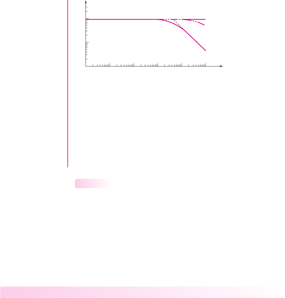
cascode circuit. From the hand analysis, the two corner frequencies are 12 Mz and
38.3 MHz. Since these frequencies are fairly close, we expect the actual response to
show the effects of both capacitances. This hypothesis is verified and demonstrated
nea80644_ch07_469-558.qxd 06/13/2009 08:07 PM Page 531 F506 Hard disk:Desktop Folder:Rakesh:MHDQ134-07:
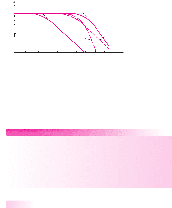
532 Part 1 Semiconductor Devices and Basic Applications
in the computer analysis results. The curves marked “
C
π
only” and “
“C
π
and
C
μ
only” are fairly close together, and their slopes are steeper than
−6
dB/octave, which
shows that more than one capacitor is involved in the response. At a frequency of
12 MHz, the response curve is 3 dB below the maximum asymptotic gain, and the
midband gain is 120. These values closely agree with the hand analysis results.
The curves marked “
C
L
= 5
pF” and “
C
L
= 150
pF” show the circuit response
if the transistor is ideal and only a load capacitance is included.
EXERCISE PROBLEM
*Ex 7.15: The cascode circuit in Figure 7.65 has parameters
V
+
= 12
V,
V
−
= 0
,
R
1
= 58.8
k
,
R
2
= 33.3
k
,
R
3
= 7.92
k
,
R
C
= 7.5
k
,
R
S
= 1
k
,
R
E
=
0.5 k
, and
R
L
= 2
k
. The transistor parameters are:
β = 100
,
V
BE
(on) =
0.7 V,
V
A
=∞
,
C
π
= 24
pF, and
C
μ
= 3
pF. Let
C
L
be an open circuit. (a) De-
termine the 3 dB frequencies corresponding to the input and output portions of the
equivalent circuit. (b) Calculate the small-signal midband voltage gain. (c) Corre-
late the results from parts (a) and (b) with a computer analysis. (Ans. (a)
f
Hπ
=
7.15 MHz,
f
Hμ
= 33.6
MHz, (b)
|A
v
|=22.5
)
Emitter- and Source-Follower Circuits
In this section, we analyze the high-frequency response of the emitter follower. We
will analyze the same basic circuit configuration that we have considered previously.
The results and discussions also apply to the source follower.
Figure 7.68 shows an emitter-follower circuit with the output signal at the
emitter capacitively coupled to a load. Figure 7.69(a) shows the high-frequency
small-signal equivalent circuit, with the coupling capacitors acting effectively as
short circuits.
We will rearrange the circuit so that we can gain a better insight into the circuit
behavior. We see that
C
μ
is tied to ground potential and also that
r
o
is in parallel with
R
E
and
R
L
. We may define
R
L
= R
E
R
L
r
o
In this analysis we neglect the effect of
C
L
. Figure 7.69(b) shows a rearrangement of
the circuit.
7.6.3
f (Hz)
10
7
10
6
10
5
10
4
10
8
10
9
1
10
100
200
|A
V
|
C
L
= 150 pF
C
L
= 5 pF
C
p
only
C
p
and C
m
only
Figure 7.67 PSpice analysis results for cascode circuit
nea80644_ch07_469-558.qxd 06/13/2009 08:07 PM Page 532 F506 Hard disk:Desktop Folder:Rakesh:MHDQ134-07:
Chapter 7 Frequency Response 533
We can find the impedance
Z
b
looking into the base without capacitance
C
μ
.
The current
I
b
entering the parallel combination of
r
π
and
C
π
is the same as that
coming out of the combination. The output voltage is then
V
o
= (I
b
+ g
m
V
π
)R
L
(7.126)
v
o
R
S
C
C1
C
C2
R
1
R
2
R
E
R
L
C
L
V
+
V
–
v
i
+
–
Figure 7.68 Emitter-follower circuit
(a)
(b)
R
E
g
m
V
p
C
m
C
p
+
–
V
p
C
B
E
V
o
R
L
r
p
r
o
C
L
R
B
=
R
1
⎪⎪ R
2
V
i
R
S
+
–
(c)
C
m
r
p
(1 + g
m
R
L
' )
V
i
R
S
R
L
'
C
p
1 + g
m
R
L
'
R
B
V
b
+
–
Z
b
'
C
m
C
p
R
L
'
g
m
V
p
+
–
V
p
V
o
r
p
V
i
R
S
R
B
V
b
Z
b
'
I
b
'
I
b
'
+
–
Figure 7.69 (a) High-frequency equivalent circuit of emitter follower, (b) rearranged high-
frequency equivalent circuit, and (c) high-frequency equivalent circuit with effective input
base impedance
nea80644_ch07_469-558.qxd 06/13/2009 08:07 PM Page 533 F506 Hard disk:Desktop Folder:Rakesh:MHDQ134-07:

534 Part 1 Semiconductor Devices and Basic Applications
Voltage
V
π
is given by
V
π
=
I
b
y
π
(7.127)
where
y
π
= (1/r
π
) + sC
π
Voltage
V
b
is
V
b
= V
π
+ V
o
Therefore,
Z
b
=
V
b
I
b
=
V
π
+ V
o
I
b
(7.128)
Combining Equations (7.126), (7.127), and (7.128), we obtain
Z
b
=
1
y
π
+ R
L
+
g
m
R
L
y
π
(7.129(a))
or
Z
b
=
1
y
π
(1 + g
m
R
L
) + R
L
(7.129(b))
Substituting the expression for
y
π
, we find
Z
b
=
1
1
r
π
+sC
π
×(1 + g
m
R
L
) + R
L
(7.130(a))
This can then be written as
Z
b
=
1
1
r
π
(1 + g
m
R
L
)
+
sC
π
(1 + g
m
R
L
)
+ R
L
(7.130(b))
Impedance
Z
b
is shown in the equivalent circuit in Figure 7.69(c). Equa-
tion (7.130(b)) shows that the effect of capacitance
C
π
is reduced in the emitter-
follower configuration.
Since the emitter-follower circuit has a zero and two poles, a detailed analysis of
the circuit is very tedious. From Equations (7.126) and (7.127), we have
V
o
= V
π
(y
π
+ g
m
)R
L
(7.131)
which yields a zero when
y
π
+ g
m
= 0
. Using the definition of
y
π
, the zero occurs at
f
o
=
1
2πC
π
r
π
1 + β
(7.132)
Since
r
π
/(1 + β)
is small, frequency
f
o
is usually very high.
nea80644_ch07_469-558.qxd 06/13/2009 08:07 PM Page 534 F506 Hard disk:Desktop Folder:Rakesh:MHDQ134-07:

Chapter 7 Frequency Response 535
If we make a simplifying assumption, we can determine an approximate value
of one pole. In many applications, the impedance of
r
π
(1 + g
m
R
L
)
in parallel with
C
π
/(1 + g
m
R
L
)
is large compared to
R
L
. If we neglect
R
L
, then the time constant is
τ
P
= [R
S
R
B
(1 + g
m
R
L
)r
π
]
C
μ
+
C
π
1 + g
m
R
L
(7.133(a))
and the 3 dB frequency (or pole) is
f
H
=
1
2πτ
P
(7.133(b))
EXAMPLE 7.16
Objective: Determine the frequency of a zero and a pole in the high-frequency
response of an emitter follower.
Consider the emitter-follower circuit in Figure 7.68 with parameters
V
+
= 5
V,
V
−
=−5
V,
R
S
= 0.1
k
,
R
1
= 40
k
,
R
2
= 5.72
k
,
R
E
= 0.5
k
, and
R
L
=
10 k
. The transistor parameters are:
β = 150
,
V
BE
(on) = 0.7
V,
V
A
=∞
,
C
π
=
35 pF, and
C
μ
= 4
pF.
Solution: As in previous examples, the dc analysis yields
I
CQ
= 1.02
mA. There-
fore,
g
m
= 39.2
mA/V and
r
π
= 3.82
k
.
From Equation (7.132), the zero occurs at
f
o
=
1
2πC
π
r
π
1 + β
=
1
2π(35 ×10
−12
)
3.82 × 10
3
151
⇒ 180 MHz
To determine the time constant for the high-frequency pole calculation, we
know that
1 + g
m
R
L
= 1 + g
m
(R
E
R
L
) = 1 +(39.2)(0.510) = 19.7
and
R
B
= R
1
R
2
= 405.72 = 5k
The time constant is therefore
τ
P
= [R
S
R
B
(1 + g
m
R
L
)r
π
]
C
μ
+
C
π
1 + g
m
R
L
= [(0.1)5(19.7)(3.82)] × 10
3
4 +
35
19.7
×10
−12
⇒ 0.566 ns
The 3 dB frequency (or pole) is then
f
H
=
1
2πτ
P
=
1
2π(0.566 ×10
−9
)
⇒ 281 MHz
Comment: The frequencies for the zero and the pole are very high and are not far
apart. This makes the calculations suspect. However, since the frequencies are high,
the emitter follower is a wide-bandwidth circuit.
nea80644_ch07_469-558.qxd 06/13/2009 09:03 PM Page 535 F506 Hard disk:Desktop Folder:Rakesh:MHDQ134-07:
536 Part 1 Semiconductor Devices and Basic Applications
Computer Verification: Figure 7.70 shows the results of a PSpice analysis of the
emitter follower. From the hand analysis, the 3 dB frequency is on the order of
281 MHz. However, the computer results show the 3 dB frequency to be approxi-
mately 400 MHz. We must keep in mind that at these high frequencies, distributed
parameter effects may need to be considered in the transistor to more accurately
predict the frequency response.
Also shown in the figure is the frequency response due to a 150 pF load capac-
itance. Comparing this result to the common-emitter circuit, for example, we see that
the bandwidth of the emitter-follower circuit is approximately two orders of magni-
tude larger.
High-Frequency Amplifier Design
Our analysis shows that the frequency response, or the high-frequency cutoff point of
an amplifier, depends on the transistor used, the circuit parameters, and the amplifier
configuration.
We also saw that a computer simulation is easier than a hand analysis, particu-
larly for the emitter-follower circuit. However, the parameters of the actual transistor
used in the circuit must be used in the simulation if it is to predict the circuit fre-
quency response accurately. Also, at high frequencies, additional parasitic capaci-
tances, such as the collector–substrate capacitance, may need to be included. This
was not done in our examples. Finally, in high-frequency amplifiers, the parasitic
capacitances of the interconnect lines between the devices in an IC may also be a
factor in the overall circuit response.
Test Your Understanding
*TYU 7.12 For the circuit in Figure 7.71, the transistor parameters are:
K
n
=
1 mA/V
2
,
V
TN
= 0.8
V,
λ = 0
,
C
gs
= 2
pF, and
C
gd
= 0.2
pF. Determine: (a) the
Miller capacitance, (b) the upper 3 dB frequency, and (c) the midband voltage gain.
(d) Correlate the results from parts (b) and (c) with a computer analysis. (Ans.
(a)
C
M
= 1.62
pF, (b)
f
H
= 3.38
MHz, (c)
|A
v
|=4.60
)
*TYU 7.13 For the circuit in Figure 7.72, the transistor parameters are:
V
TN
= 1
V,
K
n
= 1
mA/V
2
,
λ = 0
,
C
gd
= 0.4
pF, and
C
gs
= 5
pF. Perform a computer
simulation to determine the upper 3 dB frequency and the midband small-signal
voltage gain. (Ans.
f
H
= 64.5
MHz,
|A
v
|=0.127
)
7.6.4
f (Hz)
10
7
10
6
10
5
10
4
10
8
10
9
0.01
0.1
1
|A
V
|
C
L
= 150 pF
C
p
only
C
p
and C
m
only
Figure 7.70 PSpice analysis results for emitter follower
nea80644_ch07_469-558.qxd 06/13/2009 08:07 PM Page 536 F506 Hard disk:Desktop Folder:Rakesh:MHDQ134-07:
Chapter 7 Frequency Response 537
7.7 DESIGN APPLICATION: A TWO-STAGE
AMPLIFIER WITH COUPLING CAPACITORS
Objective: • Design a two-stage BJT amplifier with coupling capaci-
tors such that the 3 dB frequencies associated with each stage are
equal.
Specifications: The first two stages of a multistage BJT amplifier are to be capaci-
tively coupled and the 3 dB frequency of each stage is to be 20 Hz.
Design Approach: The circuit configuration to be designed is shown in Figure 7.73.
This circuit represents the first two stages of a discrete multistage amplifier.
Choices: Assume the BJTs have parameters
V
BE
(on) = 0.7
V,
β = 200
, and
V
A
=∞
.
v
i
R
i
= 20 kΩ
C
C1
→ ∞
C
S
→ ∞
R
D
= 5 kΩ
R
1
= 150 kΩ
R
2
=
50 kΩ
R
S
=
2 kΩ
+5 V
–5 V
+
–
Figure 7.71 Figure for Exercise TYU 7.12
C
C1
→ ∞
R
i
= 10 kΩ
R
G
= 100 kΩ
I
G
=
1 mA
C
G
→ ∞
v
i
C
C2
→ ∞
R
L
=
2 kΩ
R
D
=
4 kΩ
v
o
–5 V
+5 V
+
–
Figure 7.72 Figure for Exercise TYU 7.13
v
i
C
C1
C
C2
V
CC
= 5 V
R
1
=
55 kΩ
R
1
=
55 kΩ
R
C1
=
3.5 kΩ
R
C2
R
E1
=
1 kΩ
R
E2
=
1 kΩ
R
2
=
31 kΩ
R
2
=
31 kΩ
+
–
R
i
R
i
Figure 7.73 Two-stage BJT amplifier with coupling capacitors for design application
nea80644_ch07_469-558.qxd 06/13/2009 08:07 PM Page 537 F506 Hard disk:Desktop Folder:Rakesh:MHDQ134-07: