Neamen D. Microelectronics: Circuit Analysis and Design
Подождите немного. Документ загружается.

628 Part 2 Analog Electronics
Basic Amplifier
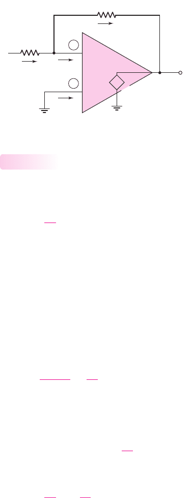
We analyze the circuit in Figure 9.8 by considering the ideal equivalent circuit shown
in Figure 9.9. The closed-loop voltage gain, or simply the voltage gain, is defined as
A
v
=
v
O
v
I
(9.8)
We stated that if the open-loop gain A
od
is very large, then the two inputs v
1
and v
2
must be nearly equal. Since v
2
is at ground potential, voltage v
1
must also be
approximately zero volts. We must point out, however, that having v
1
be essentially
at ground potential does not imply that terminal (1) is grounded. Rather, terminal (1)
is said to be at virtual ground; that is, it is essentially zero volts, but it does not
provide a current path to ground. The virtual ground concept will be used in the
analysis of ideal op-amp circuits. To repeat this important concept, with terminal 1
being at virtual ground means that terminal 1 is essentially at zero volts, but is not
connected to ground potential.
From Figure 9.9, we can write
i
1
=
v
I
−v
1
R
1
=
v
I
R
1
(9.9)
Since the current into the op-amp is assumed to be zero, current i
l
must flow through
resistor R
2
to the output terminal, which means that
i
1
= i
2
.
The output voltage is given by
v
O
= v
1
−i
2
R
2
= 0 −
v
I
R
1
R
2
(9.10)
Therefore, the closed-loop voltage gain is
A
v
=
v
O
v
I
=−
R
2
R
1
(9.11)
For the ideal op-amp, the closed-loop voltage gain is a function of the ratio of two
resistors; it is not a function of the transistor parameters within the op-amp circuit.
Again, the minus sign implies a phase reversal. If the input voltage
v
I
is positive, then,
because
v
1
is essentially at ground potential, the output voltage
v
O
must be negative,
or below ground potential. Also note that if the output terminal is open-circuited, cur-
rent i
2
must flow back into the op-amp. However, since the output impedance for the
ideal case is zero, the output voltage is not a function of this current that flows back
into the op-amp and is not dependent on the load.
9.2.1
R
1
1
2
–
+
A
od
(v
2
– v
1
)
v
I
v
1
v
2
= 0
0
v
O
i
2
R
2
i
1
0
+
–
Figure 9.9 Inverting op-amp equivalent circuit
nea80644_ch09_619-686.qxd 6/19/09 4:25 AM Page 628 pmath DATA-DISK:Desktop Folder:18.6.09:MHDQ134-09:
Chapter 9 Ideal Operational Amplifiers and Op-Amp Circuits 629
We can also determine the input resistance seen by the voltage source
v
I
.
Because of the virtual ground, we have, from Equation (9.9)
i
1
= v
I
/R
1
The input resistance is then defined as
R
i
=
v
I
i
1
= R
1
(9.12)
This shows that the input resistance seen by the source is a function of R
1
only, and
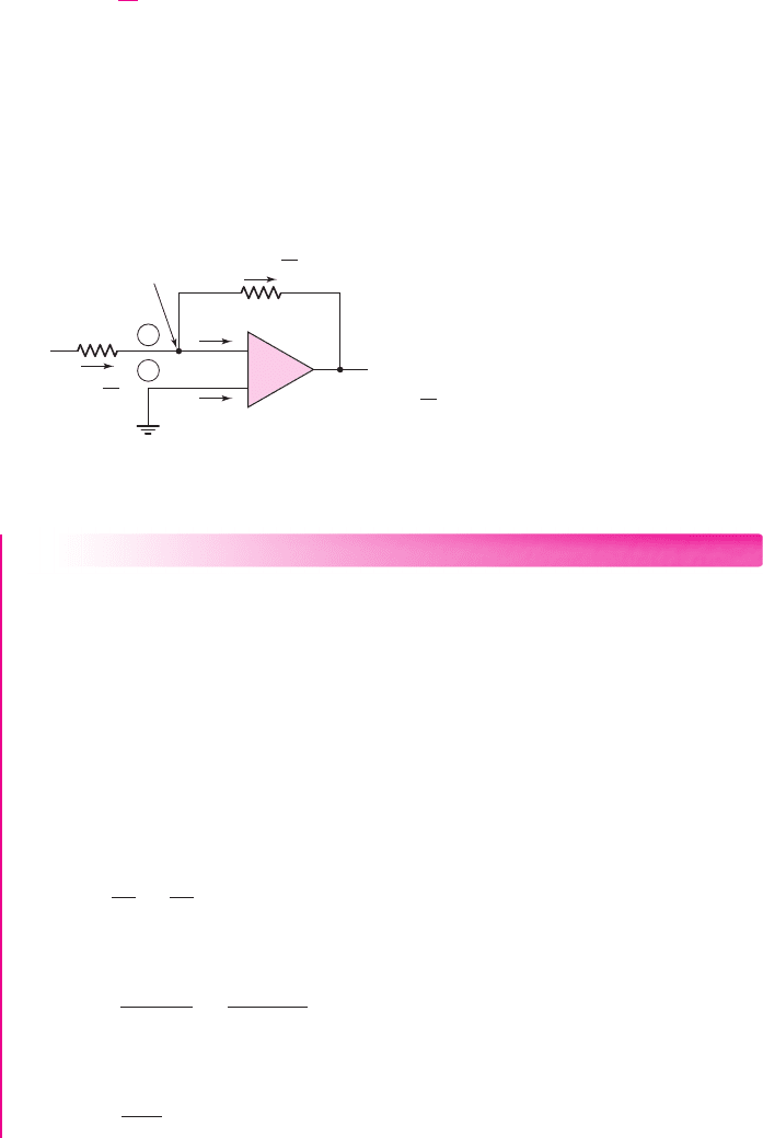
is a result of the “virtual ground” concept. Figure 9.10 summarizes our analysis of
the inverting amplifier circuit.
Since there are no coupling capacitors in the op-amp circuit, the input and output
voltages, as well as the currents in the resistors, can be dc signals. The inverting
op-amp can then amplify dc voltages.
1
2
–
+
R
1
R
2
+
–
Virtual ground, v
1
= 0
i
2
= i
1
=
v
O
= 0 – i
2
R
2
v
I
v
I
R
1
R
2
R
1
i
1
=
v
I
R
1
0
0
0 V
= – v
I
–
+
Figure 9.10 Currents and voltages in the inverting op-amp
DESIGN EXAMPLE 9.1
Objective: Design an inverting amplifier with a specified voltage gain.
Specifications: The circuit configuration to be designed is shown in Figure 9.10.
Design the circuit such that the voltage gain is
A
v
=−5
. Assume the op-amp is
driven by an ideal sinusoidal source,
v
s
= 0.1 sin ωt
(V), that can supply a maximum
current of 5
μ
A. Assume that frequency
ω
is low so that any frequency effects can be
neglected.
Design Pointer: If the sinusoidal input signal source has a nonzero output resis-
tance, the op-amp must be redesigned to provide the specified voltage gain.
Initial Solution: The input current is given by
i
1
=
v
I
R
1
=
v
s
R
1
If
i
1
(max) = 5 μA
, then we can write
R
1
=
v
s
(max)
i
1
(max)
=
0.1
5 × 10
−6
⇒ 20 k
The closed-loop gain is given by
A
v
=
−R
2
R
1
=−5
nea80644_ch09_619-686.qxd 6/19/09 4:25 AM Page 629 pmath DATA-DISK:Desktop Folder:18.6.09:MHDQ134-09:
630 Part 2 Analog Electronics
We then have
R
2
= 5R
1
= 5(20) = 100 k
Trade-offs: If the signal source has a finite output resistance and the desired output
voltage is
v
o
=−0.5 sin ωt
, the circuit must be redesigned. Assume the output resis-
tance of the source is
R
S
= 1
k
.
Redesign Solution: The output resistance of the signal source is now part of the
input resistance to the op-amp. We now write
R
1
+ R
S
=
v
s
(max)
i
1
(max)
=
0.1
5 × 10
−6
⇒ 20 k
Since
R
S
= 1
k
, we then have
R
1
= 19
k
. The feedback resistor is then
R
2
=
5(R
1
+ R
S
) = 5(19 +1) = 100 k
.
Comment: The output resistance of the signal source must be included in the design
of the op-amp to provide a specified voltage gain.
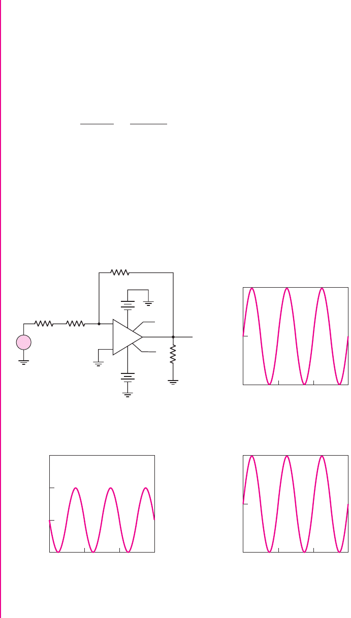
Computer Verification: Figure 9.11(a) shows the PSpice circuit schematic with the
source resistance of 1 k
and an input resistance of 19 k
. Figure 9.11(b) shows the
+
~
–
100
1.0
0.5
0
–0.5
0123
0
–100
0123
100 kΩ
+
0
0
0
0
1
4
2
3
7
5
6
0
15 V
–
–
+
Time (ms)
Time (ms)Time (ms)
v
1
+
15 V
–
v
2
v–
v+
v
3
R
4
R
3
19 kΩ
100 kΩ
R
1
1 kΩ
R
2
(a) (b)
(c) (d)
V
out
(V)
5.0
0
–5.0
0123
I
in
(mA)
V
in
(mV)
mA–741
U
1
v
out
Figure 9.11 (a) PSpice circuit schematic, (b) input signal, (c) output signal, and (d) input
current signal for Example 9.1
nea80644_ch09_619-686.qxd 6/19/09 4:25 AM Page 630 pmath DATA-DISK:Desktop Folder:18.6.09:MHDQ134-09:

Chapter 9 Ideal Operational Amplifiers and Op-Amp Circuits 631
100 mV sinusoidal input signal. Figure 9.11(c) is the output signal which shows that
a gain of 5 (magnitude) has been achieved and also shows that the output signal is
180 degrees out of phase with respect to the input signal. Finally, the input current is
shown in Figure 9.11(d) with a maximum value of 5
μ
A. The actual circuit charac-
teristics are not influenced to any great extent by the nonideal parameters of the
μ
A-741 op-amp used in the circuit simulation.
EXERCISE PROBLEM
Ex 9.1: Design an ideal inverting op-amp circuit such that the voltage gain is
A
v
=−25
. The maximum current in any resistor is to be limited to
10 μ
A with
the input voltage in the range
−25 ≤ v
I
≤+25
mV. (a) What are the values of
R
1
and
R
2
? (b) What is the range of output voltage
v
O
? (Ans. (a)
R
1
= 2.5
k
,
R
2
= 62.5
k
; (b)
−0.625 ≤ v
O
≤ 0.625
V)
Problem-Solving Technique: Ideal Op-Amp Circuits
1. If the noninverting terminal of the op-amp is at ground potential, then the
inverting terminal is at virtual ground. Sum currents at this node, assuming
zero current enters the op-amp itself.
2. If the noninverting terminal of the op-amp is not at ground potential, then the
inverting terminal voltage is equal to that at the noninverting terminal. Sum
currents at the inverting terminal node, assuming zero current enters the
op-amp itself.
3. For the ideal op-amp circuit, the output voltage is determined from either step 1
or step 2 above and is independent of any load connected to the output terminal.
Amplifier with a T-Network
Assume that an inverting amplifier is to be designed having a closed-loop voltage
gain of
A
v
=−100
and an input resistance of
R
i
= R
1
= 50 k
. The feedback
resistor R
2
would then have to be 5 M
. However this resistance value is too large
for most practical circuits.
Consider the op-amp circuit shown in Figure 9.12 with a T-network in the feed-
back loop. The analysis of this circuit is similar to that of the inverting op-amp circuit
of Figure 9.10. At the input, we have
i
1
=
v
I
R
1
= i
2
(9.13)
9.2.2
1
2
R
1
R
3
R
4
R
2
i
3
v
O
v
X
v
I
i
4
i
2
i
1
v
1
= 0
0
0
–
+
Figure 9.12 Inverting op-amp with T-network
nea80644_ch09_619-686.qxd 6/19/09 4:25 AM Page 631 pmath DATA-DISK:Desktop Folder:18.6.09:MHDQ134-09:

632 Part 2 Analog Electronics
We can also write that
v
X
= 0 −i
2
R
2
=−v
I
R
2
R
1
(9.14)
If we sum the currents at the node
v
X
, we have
i
2
+i
4
= i
3
which can be written
−
v
X
R
2
−
v
X
R
4
=
v
X
−v
O
R
3
(9.15)
or
v
X
1
R
2
+
1
R
4
+
1
R
3
=
v
O
R
3
(9.16)
Substituting the expression for
v
X
from Equation (9.14), we obtain
−v
I
R
2
R
1
1
R
2
+
1
R
4
+
1
R
3
=
v
O
R
3
(9.17)
The closed-loop voltage gain is therefore
A
v
=
v
O
v
I
=−
R
2
R
1
1 +
R
3
R
4
+
R
3
R
2
(9.18)
The advantage of using a T-network is demonstrated in the following example.
DESIGN EXAMPLE 9.2
Objective: An op-amp with a T-network is to be designed as a microphone
preamplifier.
Specifications: The circuit configuration to be designed is shown in Figure 9.12.
The maximum microphone output voltage is 12 mV (rms) and the microphone has an
output resistance of 1 k
. The op-amp circuit is to be designed such that the maxi-
mum output voltage is 1.2 V (rms). The input amplifier resistance should be fairly
large, but all resistance values should be less that 500 k
.
Choices: The final design should use standard resistor values. In addition, standard
resistors with tolerances of
±2
percent are to be considered.
Solution: We need a voltage gain of
|A
v
|=
1.2
0.012
= 100
Equation (9.18) can be written in the form
A
v
=−
R
2
R
1
1 +
R
3
R
4
−
R
3
R
1
If, for example, we arbitrarily choose
R
2
R
1
=
R
3
R
1
= 8
, then
−100 =−8
1 +
R
3
R
4
−8
nea80644_ch09_619-686.qxd 6/19/09 4:25 AM Page 632 pmath DATA-DISK:Desktop Folder:18.6.09:MHDQ134-09:

Chapter 9 Ideal Operational Amplifiers and Op-Amp Circuits 633
which yields
R
3
R
4
= 10.5
The effective R
1
must include the R
S
resistance of the microphone. If we set
R
1
= 49 k
so that
R
1,eff
= 50 k
, then
R
2
= R
3
= 400 k
and
R
4
= 38.1k
Design Pointer: If we need to use standard resistance values in our design, then,
using Appendix C, we can choose
R
1
= 51 k
so that
R
1,eff
= 52 k
, and we can
choose
R
2
= R
3
= 390
k. Then, using Equation (9.18), we have
A
v
=−100 =
−R
2
R
1,eff
1 +
R
3
R
4
−
R
3
R
1,eff
=
−390
52
1 +
390
R
4
−
390
52
which yields
R
4
= 34.4k
. We may use a standard resistor of
R
4
= 33 k
. This
resistance value then produces a voltage gain of
A
v
=−103.6
.
Trade-offs: If we consider
±2
percent tolerances in the standard resistor values, the
voltage gain can be written as
A
v
=
−R
2
(1 ± 0.02)
1k + R
1
(1 ± 0.02)
1 +
R
3
(1 ± 0.02)
R
4
(1 ± 0.02)
−
R
3
(1 ± 0.02)
1k + R
1
(1 ± 0.02)
or
A
v
=
−390(1 ± 0.02)
1 + 51(1 ±0.02)
1 +
390(1 ± 0.02)
33(1 ± 0.02)
−
390(1 ± 0.02)
1 + 51(1 ±0.02)
Analyzing this equation, we find the maximum magnitude as
|A
v
|
max
= 111.6
or
+7.72
percent, and the minimum magnitude as
|A
v
|
min
= 96.3
or
−7.05
percent.
Comment: As required, all resistor values are less than 500 k
. Also the resistance
ratios in the voltage gain expression are approximately equal. As with most design
problems, there is no unique solution. We must keep in mind that, because of resistor
value tolerances, the actual gain of the amplifier will have a range of values.
EXERCISE PROBLEM
Ex 9.2: Design an ideal inverting op-amp circuit with a T-network that has a
closed-loop voltage gain of
A
v
=−75
and an input resistance of
R = 20 k
. The
maximum resistor value is to be limited to
200 k
. (Ans. Let
R
1
= 20 k
and
R
2
= R
3
= 160
k
. Then
R
4
= 21.7k.)
The amplifier with a T-network allows us to obtain a large gain using reasonably
sized resistors.
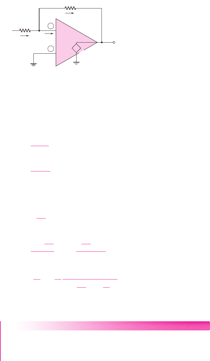
Effect of Finite Gain
A finite open-loop gain A
od
, also called the finite differential-mode gain, affects the
closed-loop gain of an inverting amplifier. We will consider nonideal effects in
9.2.3
nea80644_ch09_619-686.qxd 6/19/09 4:25 AM Page 633 pmath DATA-DISK:Desktop Folder:18.6.09:MHDQ134-09:
634 Part 2 Analog Electronics
op-amps in a later chapter; here, we will determine the magnitude of A
od
required to
approach the ideal case.
Consider the inverting op-amps shown in Figure 9.13. As before, we assume an
infinite input resistance at terminals (1) and (2), which means the input currents to the
op-amp are zero.
The current through R
1
can be written as
i
1
=
v
I
−v
1
R
1
(9.19)
and the current through R
2
is
i
2
=
v
1
−v
O
R
2
(9.20)
The output voltage is now given by
v
O
=−A
od
v
1
so that the terminal (1) voltage can be written as
v
1
=−
v
O
A
od
(9.21)
Combining Equations (9.21), (9.19), and (9.20), and setting
i
1
= i
2
, we obtain
i
1
=
v
I
+
v
O
A
od
R
1
= i
2
=
−
v
O
A
od
−v
O
R
2
(9.22)
Solving for the closed-loop voltage gain, we find that
A
v
=
v
O
v
I
=−
R
2
R
1
1
1 +
1
A
od
1 +
R
2
R
1
(9.23)
Equation (9.23) shows that if
A
od
→∞
, the ideal closed-loop voltage gain reduces
to that given by Equation (9.11).
EXAMPLE 9.3
Objective: Determine the deviation from the ideal due to a finite differential gain.
Consider an inverting op-amp with
R
1
= 10 k
and
R
2
= 100 k
. Determine
the closed-loop gain for:
A
od
= 10
2
, 10
3
, 10
4
, 10
5
, and 10
6
. Calculate the percent
deviation from the ideal gain.
R
1
R
2
1
2
–
+
A
od
(v
2
– v
1
)
v
I
v
1
v
2
= 0
0
v
O
i
2
i
1
+
–
Figure 9.13 Equivalent circuit of the inverting op-amp with a finite differential-mode gain
nea80644_ch09_619-686.qxd 6/19/09 4:25 AM Page 634 pmath DATA-DISK:Desktop Folder:18.6.09:MHDQ134-09:

Chapter 9 Ideal Operational Amplifiers and Op-Amp Circuits 635
Solution:
The ideal closed-loop gain is
A
v
=−
R
2
R
1
=−
100
10
=−10
If
A
od
= 10
2
, we have, from Equation (9.23),
A
v
=−
100
10
·
1
1 +
1
10
2
1 +
100
10
=
−10
(1 + 0.11)
=−9.01
which is a 9.9 percent deviation from the ideal. For the other differential gain values
we have the following results:
Comment: For this case, the open-loop gain must be on the order of at least 10
3
in
order to be within 1 percent of the ideal gain. If the ideal closed-loop gain changes, a
new value of open-loop gain must be determined in order to meet the specified re-
quirements. As we will see in Chapter 14, at low frequencies, most op-amp circuits
have gains on the order of 10
5
, so achieving the required accuracy is not difficult.
EXERCISE PROBLEM
Ex 9.3: (a) An inverting op-amp circuit is to be designed using an op-amp with a
finite differential voltage gain of
A
od
= 10
4
. The closed-loop voltage gain is to be
A
v
=−15.0
and the input resistance is to be
R = 25
k
. What is the required
value of
R
2
? (b) Using the results of part (a), what is the closed-loop voltage gain
if (i)
A
od
= 10
5
and (ii)
A
od
= 10
3
? (Ans. (a)
R
1
= 25
k
,
R
2
= 375.6
k
;
(b) (i)
A
v
=−15.0216
, (ii)
A
v
=−14.787)
Test Your Understanding
TYU 9.1 (a) Design an ideal inverting op-amp circuit such that
A
v
=−12
. Let
R
2
= 240 k
. (b) Using the results of part (a), find
i
1
when (i)
v
I
=−0.15
V and
(ii)
v
I
=+0.25
V. (Ans. (a)
R
1
= 20 k
; (b) (i)
i
1
=−7.5 μ
A, (ii)
i
1
= 12.5 μ
A)
TYU 9.2 Consider Example 9.1. Suppose the source resistance is not a constant, but
varies within the range
0.7k ≤ R
S
≤ 1.3k
. Using the results of Example 9.1,
what is the range in (a) the voltage gain
A
v
and (b) the input current i
1
. (c) Is the
specified maximum input current still maintained? (Ans. (a)
4.926 ≤ A
v
≤ 5.076
,
(b)
4.926 ≤ i
1
≤ 5.076 μ
A)
TYU 9.3 Consider an inverting op-amp circuit as shown in Figure 9.13 with
R
1
= 20 k
and
R
2
= 200 k
. The op-amp is ideal except the open-loop gain is
A
od
= 10
4
.
Determine (a)
v
1
and
v
O
when
v
I
= 50
mV, (b)
v
1
and
v
I
when
v
O
= 5
V, and (c)
v
I
and
v
O
when
v
1
= 0.20
mV. (Ans. (a)
v
O
=−0.49945
V,
v
1
=+49.945 μ
V;
(b)
v
I
=−0.50055
V,
v
1
=−0.5
mV; (c)
v
O
=−2.0
V,
v
I
= 0.20022
V)
A
od
A
v
Deviation (%)
10
2
−9.01
9.9
10
3
−9.89
1.1
10
4
−9.989
0.11
10
5
−9.999
0.01
10
6
−9.9999
0.001
nea80644_ch09_619-686.qxd 6/19/09 3:59 PM Page 635 pmath DATA-DISK:Desktop Folder:19/6/2009:MHDQ134-09 Folder:MHDQ134-09
636 Part 2 Analog Electronics
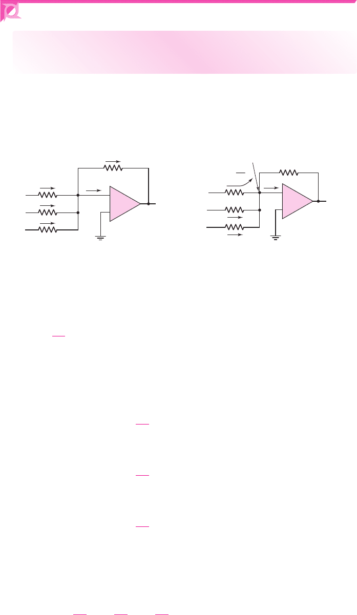
9.3 SUMMING AMPLIFIER
Objective: • Analyze and understand the characteristics of the
summing operational amplifier.
To analyze the op-amp circuit shown in Figure 9.14(a), we will use the superposition
theorem and the concept of virtual ground. Using the superposition theorem, we will
determine the output voltage due to each input acting alone. We will then alge-
braically sum these terms to determine the total output.
–
+
R
1
R
F
R
2
R
3
–
+
R
1
R
F
R
2
R
3
(
a
)(
b
)
i
4
v
1
= 0
v
O
v
I1
i
1
v
I2
i
2
v
I3
i
3
0
v
O
v
I1
i
2
= 0
i
3
= 0
v
I3
= 0
v
I2
= 0
0
i
1
=
v
I1
R
1
Virtual ground
–
+
–
+
Figure 9.14 (a) Summing op-amp amplifier circuit and (b) currents and voltages in the
summing amplifier
If we set
v
I2
= v
I3
= 0
, the current i
1
is
i
1
=
v
I1
R
1
(9.24)
Since
v
I2
= v
I3
= 0
and the inverting terminal is at virtual ground, the currents i
2
and i
3
must both be zero. Current i
1
does not flow through either R
2
or R
3
, but the en-
tire current must flow through the feedback resistor R
F
, as indicated in Figure 9.14(b).
The output voltage due to
v
I1
acting alone is
v
O
(v
I1
) =−i
1
R
F
=−
R
F
R
1
v
I1
(9.25)
Similarly, the output voltages due to
v
I2
and
v
I3
acting individually are
v
O
(v
I2
) =−i
2
R
F
=−
R
F
R
2
v
I2
(9.26)
and
v
O
(v
I3
) =−i
3
R
F
=−
R
F
R
3
v
I3
(9.27)
The total output voltage is the algebraic sum of the individual output voltages, or
v
O
= v
O
(v
I1
) + v
O
(v
I2
) + v
O
(v
I3
)
(9.28)
which becomes
v
O
=−
R
F
R
1
v
I1
+
R
F
R
2
v
I2
+
R
F
R
3
v
I3
(9.29)
nea80644_ch09_619-686.qxd 6/19/09 4:25 AM Page 636 pmath DATA-DISK:Desktop Folder:18.6.09:MHDQ134-09:

Chapter 9 Ideal Operational Amplifiers and Op-Amp Circuits 637
The output voltage is the sum of the three input voltages, with different weighting fac-
tors. This circuit is therefore called the inverting summing amplifier. The number of
input terminals and input resistors can be changed to add more or fewer voltages.
A special case occurs when the three input resistances are equal. When
R
1
= R
2
= R
3
≡
R, then
v
O
=−
R
F
R
1
(v
I1
+v
I2
+v
I3
)
(9.30)
This means that the output voltage is the sum of the input voltages, with a single
amplification factor.
Discussion: Up to this point, we have seen that op-amps can be used to multiply a
signal by a constant and sum a number of signals with prescribed weights. These are
mathematical operations. Later in the chapter, we will see that op-amps can also be
used to integrate and differentiate. These circuits are the building blocks needed to
perform analog computations—hence the original name of operational amplifier. Op-
amps, however, are versatile and can do much more than just perform mathematical
operations, as we will continue to observe through the remainder of the chapter.
DESIGN EXAMPLE 9.4
Objective: Design a summing amplifier to produce a specified output signal.
Specifications: The output signal generated from an ideal amplifier circuit is
v
O1
= 1.2 −0.5 sin ω t
(V). Design a summing amplifier to be connected to the am-
plifier circuit such that the output signal is
v
O
= 2 sin ωt
(V).
Choices: Standard precision resistors with tolerances of
±1
percent are to be used in
the final design. Assume an ideal op-amp is available.
Solution: In this case, we need only two inputs to the summing amplifier, as shown
in Figure 9.14. One input to the summing amplifier is the output of the ideal ampli-
fier circuit and the second input should be a dc voltage to cancel the
+1.2
V signal
from the amplifier circuit. If the voltage gains of each input to the summing amplifier
are equal, then an input of
−1.2
V at the second input will cancel the
+1.2
V from the
amplifier circuit.
For a
−0.5
V sinusoidal input signal and a desired
2V
sinusoidal output signal,
the summing amplifier gain must be
A
v
=
−R
F
R
1
=
2
−0.5
=−4
If we choose the input resistances to be
R
1
= R
2
= 30 k
, then the feedback resis-
tance must be
R
F
= 120 k
.
Trade-offs: From Appendix C, we can choose precision resistor values of
R
F
= 124 k
and
R
1
= R
2
= 30.9
k
. The ratio of the ideal resistors is 4.013. Con-
sidering the
±1
percent tolerance values, the output of the summing amplifier is
v
O
=
−R
F
(1 ± 0.01)
R
1
(1 ± 0.01)
· (1.2 − 0.5 sin ωt) −
R
F
(1 ± 0.01)
R
2
(1 ± 0.01)
· (−1.2)
The dc output voltage is in the range
−0.1926 ≤ v
O
(dc)
≤ 0.1926
V and the peak ac
output voltage is in the range
1.967 ≤ v
O
(ac)
≤ 2.047
V.
Comment: In this example, we have used a summing amplifier to amplify a time-
varying signal and eliminate a dc voltage (ideally).
nea80644_ch09_619-686.qxd 6/19/09 4:25 AM Page 637 pmath DATA-DISK:Desktop Folder:18.6.09:MHDQ134-09: