Neamen D. Microelectronics: Circuit Analysis and Design
Подождите немного. Документ загружается.

658 Part 2 Analog Electronics
and
i
O
= g
m
v
d
(9.82)
where
v
d
=
470
470 + 33,000
· v
I
= 0.014v
I
(9.83)
From the OTA circuit, we have
g
m
=
i
cont
2V
T
(9.84)
where
V
T
= 0.026 V
at room temperature. The control current is given by
i
cont
=
v
C
25 k
(9.85)
where
v
C
may be in the range
2 ≤ v
C
≤ 10 V
. The transconductance of the transcon-
ductance operational amplifier is controlled by the control voltage
v
C
.
Combining equations, we can write the voltage gain as
A
v
=
v
O
v
I
= 0.269v
C
(9.86)
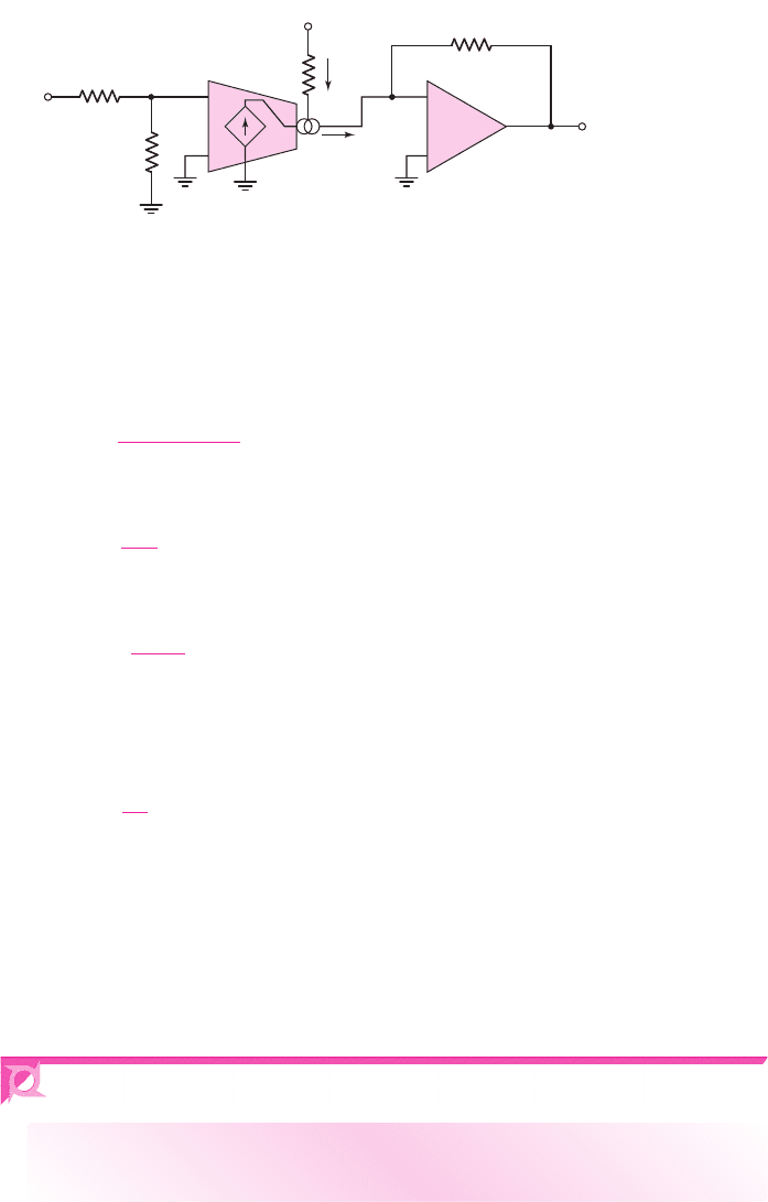
The amplifier shown in Figure 9.39 is then a voltage-controlled voltage amplifier.
The amplification factor is a function of the control voltage
v
C
.This circuit can be
used as an amplitude modulator. The
v
I
input may be the carrier signal and the
v
C
input may be the audio signal.
OTAs can also be used to design voltage-controlled filters and voltage-
controlled oscillators.
9.7 OP-AMP CIRCUIT DESIGN
Objective: • Design several ideal op-amp circuits with given design
specifications.
Up to this point, we have mainly been concerned with analyzing ideal op-amp
circuits and designing a few basic op-amp circuits. In this section, we will design
three specific op-amp circuits. We will assume that these circuits will be fabricated
as integrated circuits so that we are not limited to standard resistor values.
25 kΩ
R
F
= 25 kΩ
33 kΩ
470 Ω
+
–
+
–
v
C
v
O
v
I
+
–
v
d
i
cont
g
m
v
d
i
O
Figure 9.39 Example of a voltage-controlled voltage amplifier using an OTA
nea80644_ch09_619-686.qxd 6/19/09 4:25 AM Page 658 pmath DATA-DISK:Desktop Folder:18.6.09:MHDQ134-09:
Chapter 9 Ideal Operational Amplifiers and Op-Amp Circuits 659
Summing Op-Amp Circuit Design
In an inverting summing op-amp, each input is connected to the inverting terminal
through a resistor. The summing op-amp can be designed such that the output is
v
O
=−a
1
v
I1
−a
2
v
I2
+a
3
v
I3
+a
4
v
I4
(9.87)
where the coefficients
a
i
are all positive. In one design, we could apply voltages
v
I3
and
v
I4
to inverter amplifiers and use the summing op-amp considered previously.
This design would require three such op-amps. Alternatively, we could use the re-
sults of Exercise TYU 9.8 to design a summing circuit that uses only one op-amp and
is more versatile.
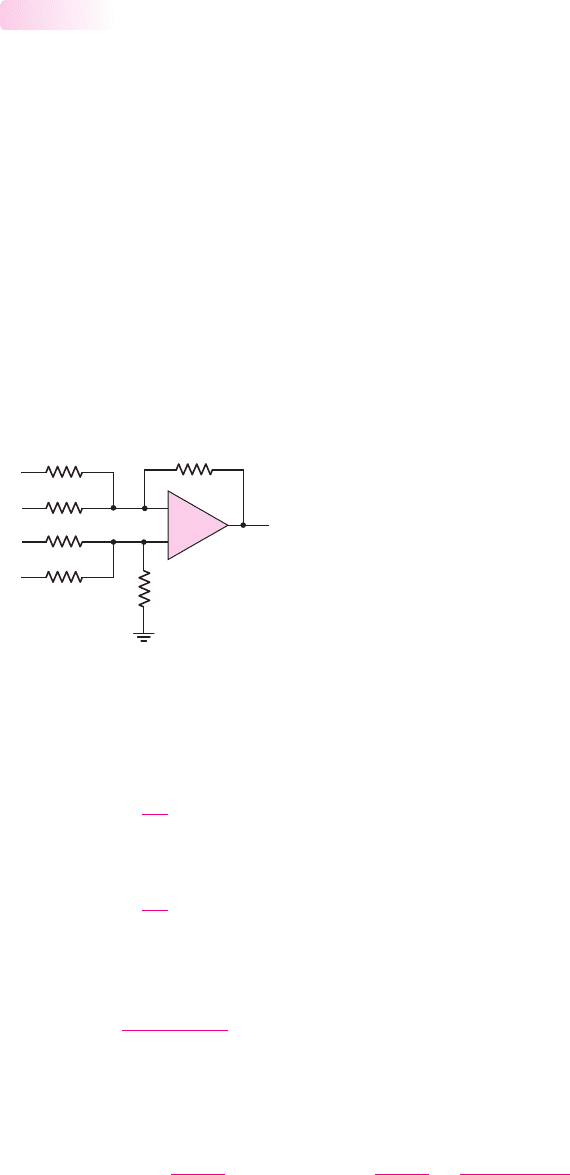
Consider the circuit shown in Figure 9.40. Resistor
R
C
provides more versa-
tility in the design. When we consider nonideal effects, such as bias currents, in
op-circuits, in Chapter 14, we will impose a design constraint on the relationship
between the resistors connected to the inverting and noninverting terminals. In this
section, we will continue to use the ideal op-amp.
9.7.1
v
1
v
2
R
1
R
2
R
A
R
B
R
C
R
F
v
I1
v
1
v
2
v
I2
v
I3
v
I4
–
+
v
O
Figure 9.40 Generalized op-amp summing amplifier
To determine the output voltage of our circuit, we use superposition. The inputs
v
I1
and
v
I2
produce the usual outputs, as follows:
v
O
(v
I1
) =−
R
F
R
1
v
I1
(9.88(a))
and
v
O
(v
I2
) =−
R
F
R
2
v
I2
(9.88(b))
We then determine the output due to
v
I3
, with all other inputs set equal to zero. We
can write
v
2
(v
I3
) =
R
B
R
C
R
A
+ R
B
R
c
v
I3
= v
1
(v
I3
)
(9.89)
Since
v
I1
= v
I2
= 0
, the voltage
v
2
(v
I3
)
is the input to a noninverting op-amp with
R
1
and
R
2
in parallel.
Then,
v
O
(v
I3
) =
1 +
R
F
R
1
R
2
v
1
(v
I3
) =
1 +
R
F
R
1
R
2
R
B
R
C
R
A
+ R
B
R
C
v
I3
(9.90)
nea80644_ch09_619-686.qxd 6/19/09 4:25 AM Page 659 pmath DATA-DISK:Desktop Folder:18.6.09:MHDQ134-09:

660 Part 2 Analog Electronics
which can be rearranged as follows:
v
O
(v
I3
) =
1 +
R
F
R
N
R
P
R
A
v
I3
(9.91)
Here, we define
R
N
= R
1
R
2
(9.92(a))
and
R
P
= R
A
R
B
R
C
(9.92(b))
The output voltage due to
v
I4
is similarly determined and is
v
O
(v
I4
) =
1 +
R
F
R
N
R
P
R
B
v
I4
(9.93)
The total output voltage is then the sum of the individual terms, or
v
O
=−
R
F
R
1
v
I1
−
R
F
R
2
v
I2
+
1 +
R
F
R
N
R
P
R
A
v
I3
+
R
P
R
B
v
I4
(9.94)
This form of the output voltage is the same as the desired output given by Equa-
tion (9.87).
DESIGN EXAMPLE 9.10
Objective: Design a summing op-amp to produce the output
v
O
=−10v
I1
−4v
I2
+5v
I3
+2v
I4
The smallest resistor value allowable is
20 k
. Consider the circuit in Figure 9.40.
Solution: First we determine the values of resistors
R
1
,
R
2
, and
R
F
, and then we can
determine the noninverting terms. We know that
R
F
R
1
= 10 and
R
F
R
2
= 4
Resistor
R
1
will be the smallest value, so we can set
R
1
= 20 k
. Then,
R
F
= 200 k and R
2
= 50 k
The multiplying factor in the noninverting terms becomes
1 +
R
F
R
1
R
2
=
1 +
200
2050
= 15
We then need
(15)
R
P
R
A
= 5 and (15)
R
P
R
B
= 2
If we take the ratio of these two expressions, we have
R
B
R
A
=
5
2
nea80644_ch09_619-686.qxd 6/19/09 4:25 AM Page 660 pmath DATA-DISK:Desktop Folder:18.6.09:MHDQ134-09:

Chapter 9 Ideal Operational Amplifiers and Op-Amp Circuits 661
If we choose
R
A
= 80 k
, then
R
B
= 200 k
,
R
P
= 26.67 k
, and
R
C
becomes
R
C
= 50 k
.
Comment: We could change the number of inputs to either the inverting or nonin-
verting terminal, depending on the desired output versus input voltage response.
EXERCISE PROBLEM
Ex 9.10: Consider the summing op-amp in Figure 9.40. Let
R
F
= 80 k
,
R
1
= 40 k
,
R
2
= 20 k
,
R
A
= R
B
= 50 k
, and
R
C
= 100 k
. (a) Determine
the output voltage in terms of the input voltages. (b) Determine
v
O
for
(i)
v
I1
= 0.1
V,
v
I2
= 0.15
V,
v
I3
= 0.2
V,
v
I4
= 0.3
V; and for (ii)
v
I1
=−0.2
V,
v
I2
= 0.25
V,
v
I3
=−0.1
V,
v
I4
= 0.2
V. (Ans. (a)
v
O
=−2v
I1
− 4v
I2
+
2.8v
I3
+2.8v
I4
; (b) (i)
v
O
= 0.6
V, (ii)
v
O
=−0.32
V)
Reference Voltage Source Design
In Chapter 2, we discussed the use of Zener diodes to provide a constant or reference
voltage source. A limitation, however, was that the reference voltage could never be
greater than the Zener voltage. Now, we can combine a Zener diode with an op-amp
to provide more flexibility in the design of reference voltage sources.
Consider the circuit shown in Figure 9.41. Voltage source
V
S
and resistor
R
S
bias the Zener diode in the breakdown region. The op-amp is then used as a nonin-
verting amplifier. The output voltage is
V
O
=
1 +
R
2
R
1
V
Z
(9.95)
The output current to the load circuit is supplied by the op-amp. A change in the load
current will not produce a change in the Zener diode current; consequently, voltage
regulation is much improved compared to the simple Zener diode voltage source pre-
viously considered.
Since the incremental Zener resistance is not zero, the Zener diode voltage is a
slight function of the diode current. The circuit shown in Figure 9.42 is less affected
by variations in
V
S
, since
V
S
is used only to start up the circuit. The Zener diode be-
gins to conduct when
R
4
R
3
+ R
4
V
S
> V
Z
+ V
D
∼
=
V
Z
+0.7
(9.96)
9.7.2
R
1
R
2
R
S
V
S
+
–
V
O
V
Z
–
+
Figure 9.41 Simple op-amp voltage reference circuit
R
1
R
3
R
2
R
F
+
–
R
4
D
1
V
O
V
S
v
2
I
F
V
Z
–
+
Figure 9.42 Op-amp voltage reference circuit
nea80644_ch09_619-686.qxd 6/19/09 4:26 AM Page 661 pmath DATA-DISK:Desktop Folder:18.6.09:MHDQ134-09:

662 Part 2 Analog Electronics
At this specific voltage, we have
V
O
=
1 +
R
2
R
1
V
Z
(9.97)
and
I
F
=
V
O
− V
Z
R
F
=
R
2
V
Z
R
1
R
F
(9.98)
If
V
S
decreases and diode
D
1
becomes reverse biased, the Zener diode continues to
conduct; the Zener diode current is then constant. However, if diode
D
1
is conducting,
the circuit can be designed such that variations in Zener diode current will be small.
DESIGN EXAMPLE 9.11
Objective: Design a voltage reference source with an output of 10.0 V. Use a Zener
diode with a breakdown voltage of 5.6 V. Assume the voltage regulation will be
within specifications if the Zener diode is biased between 1–1.2 mA.
Solution: Consider the circuit shown in Figure 9.42. For this example, we need
V
O
V
Z
=
1 +
R
2
R
1
=
10.0
5.6
Therefore,
R
2
R
1
= 0.786
We know that
I
F
=
V
O
− V
Z
R
F
If we set
I
F
equal to the minimum bias current, we have
1mA=
10 − 5.6
R
F
which means that
R
F
= 4.4k
. If we choose
R
2
= 30 k
, then
R
1
= 38.17 k
.
Resistors
R
3
and
R
4
can be determined from Figure 9.43. The maximum Zener
current supplied by
V
S
,
R
3
, and
R
4
should be no more than 0.2 mA. We set the cur-
rent through
D
1
equal to 0.2 mA, for
V
S
= 10 V
. We then have
V
2
= V
Z
+0.7 = 5.6 +0.7 = 6.3V
Also,
I
4
=
V
2
R
4
=
6.3
R
4
R
3
R
4
D
1
+
–
V
S
V
2
′
I
4
I
D1
I
3
V
Z
V
Z
= 5.6 V
Figure 9.43 Input circuit of the op-amp voltage reference circuit
nea80644_ch09_619-686.qxd 6/19/09 4:26 AM Page 662 pmath DATA-DISK:Desktop Folder:18.6.09:MHDQ134-09:

Chapter 9 Ideal Operational Amplifiers and Op-Amp Circuits 663
and
I
3
=
V
S
− V
2
R
3
=
10 − 6.3
R
3
=
3.7
R
3
If we set
I
4
= 0.2mA
, then
I
3
= 0.4mA R
3
= 9.25 k R
4
= 31.5k
Comment: Voltage
V
S
is used as a start-up source. Once the Zener diode is biased in
breakdown, the output will be maintained at 10.0 V, even if
V
S
is reduced to zero.
EXERCISE PROBLEM
Ex 9.11: Consider the op-amp voltage reference circuit in Figure 9.42 with para-
meters given in Example 9.11. Initially set
V
S
= 10 V
and then plot, using PSpice,
v
O
and
I
F
versus
V
S
as
V
S
decreases from 10 to 0 V. Bias the op-amp at
±15 V
.
Difference Amplifier and Bridge Circuit Design
A transducer is a device that transforms one form of energy into another form. One
type of transducer uses nonelectrical inputs to produce electrical outputs. For exam-
ple, a microphone converts acoustical energy into electrical energy. A pressure trans-
ducer is a device in which, for example, a resistance is a function of pressure, so that
pressure can be converted to an electrical signal. Often, the output characteristics of
these transducers are measured with a bridge circuit.
Figure 9.44 shows a bridge circuit. Resistance
R
3
represents the transducer, and
parameter
δ
is the deviation of
R
3
from
R
2
due to the input response of the transducer.
The output voltage
v
O1
is a measure of
δ
. If
v
O1
is an open-circuit voltage, then
v
O1
=
R
2
(1 + δ)
R
2
(1 + δ) + R
1
−
R
2
R
1
+ R
2
V
+
(9.99)
which reduces to
v
O1
= δ
R
1
R
2
R
1
+ R
2
V
+
(9.100)
Since neither side of voltage
v
O1
is at ground potential, we must connect
v
O1
to
an instrumentation amplifier. In addition,
v
O1
is directly proportional to supply volt-
age
V
+
; therefore, this bias should be a well-defined voltage reference.
DESIGN EXAMPLE 9.12
Objective: Design an amplifier system that will produce an output voltage of
±5V
when the resistance
R
3
deviates by
±1%
from the value of
R
2
. This would occur, for
example, in a system where
R
3
is a thermistor whose resistance is given by
R
3
= 200
1 +
(0.040)(T − 300)
300
k
9.7.3
+–
V
+
R
1
R
1
R
3
= R
2
(1 +
d
)
R
2
v
O1
Figure 9.44 Bridge circuit
nea80644_ch09_619-686.qxd 6/19/09 4:26 AM Page 663 pmath DATA-DISK:Desktop Folder:18.6.09:MHDQ134-09:
664 Part 2 Analog Electronics
where T is the absolute temperature. For
R
3
to vary by
±1%
means the temperature
is in the range
225 ≤ T ≤ 375 K
.
Consider biasing the bridge circuit at
V
+
= 7.5V
using a 5.6 V Zener diode.
Assume
±10 V
is available for biasing the op-amp and reference voltage source, and
that
R
1
= R
2
= 200 k
.
Solution: With
R
1
= R
2
, from Equation (9.100), we have
v
O1
=
δ
4
V
+
For
V
+
= 7.5V
and
δ = 0.01
, the maximum output of the bridge circuit is
v
O1
=
0.01875 V
. If the output of the amplifier system is to be
+5V
, the gain of the instru-
mentation amplifier must be
5/0.01875 = 266.7
. Consider the instrumentation
amplifier shown in Figure 9.26. The output voltage is given by Equation (9.67), which
can be written
v
O
v
O1
=
R
4
R
3
1 +
2R
2
R
1
= 266.7
We would like the ratios
R
4
/R
3
and
R
2
/R
1
to be the same order of magnitude. If we
let
R
3
= 15.0k
and
R
4
= 187.0k
, then
R
4
/R
3
= 12.467
and
R
2
/R
1
= 10.195
.
If we set
R
2
= 200.0k
, then
R
1
= 19.62 k
.
Resistance
R
1
can be a combination of a fixed resistance in series with a poten-
tiometer, to permit adjustment of the gain.
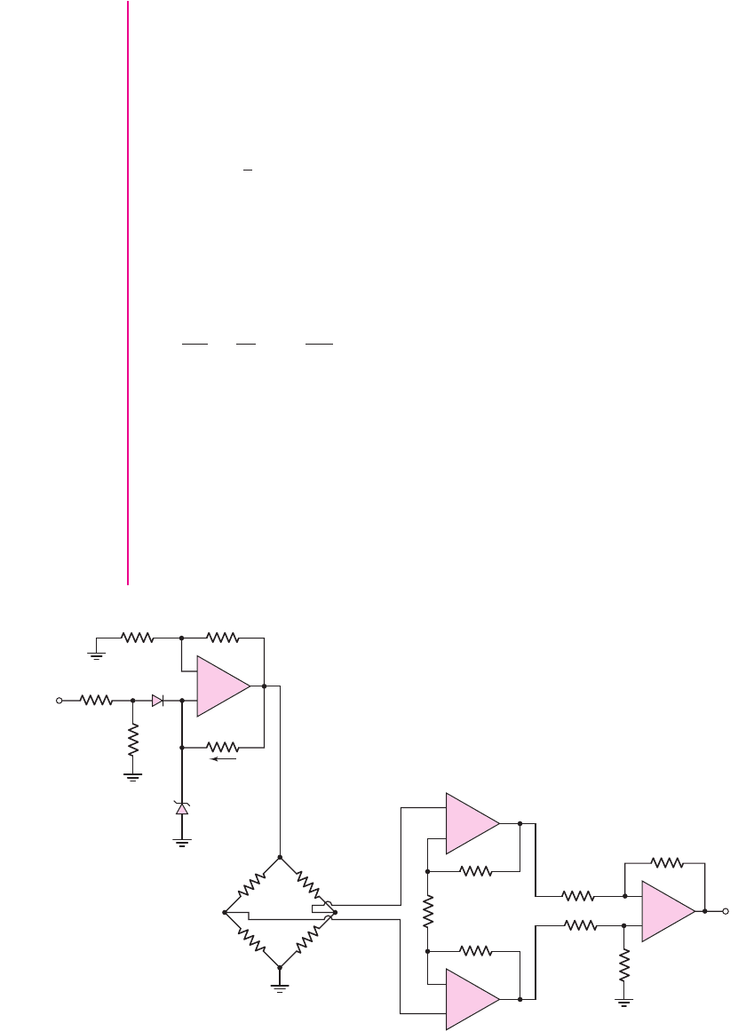
Comment: The complete design of this instrumentation amplifier is shown in Fig-
ure 9.45. Correlation of the reference voltage source design is left as an exercise.
Design Pointer: The design of fairly sophisticated op-amp circuits is quite straight-
forward when the ideal op-amp parameters are used.
+–
R
4
′
= 187 kΩ
R
4
′
= 187 kΩ
R
1
′
= 19.62 kΩ
R
2
′
= 200 kΩ
R
2
′
= 200 kΩ
R
3
′
= 15 kΩ
R
3
′
= 15 kΩ
R
1
″
= 200.0 kΩ
R
1
= 200 kΩ R
1
= 200 kΩ
R
2
= 200 kΩ
R
3
= 200(1 + d ) kΩ
R
2
″
= 67.86 kΩ
R
3
″
= 74 kΩ
R
F
″
= 7.6 kΩ
R
4
″
= 252 kΩ
+
–
D
1
v
O1
v
O
V
S
= 10 V
v
Z
= 5.6 V
i
F
= 0.25 mA
–
+
+
–
–
+
–
+
Figure 9.45 Complete amplifier system
nea80644_ch09_619-686.qxd 6/19/09 4:26 AM Page 664 pmath DATA-DISK:Desktop Folder:18.6.09:MHDQ134-09:

Chapter 9 Ideal Operational Amplifiers and Op-Amp Circuits 665
Test Your Understanding
TYU 9.14 Consider the bridge circuit in Figure 9.46. The resistance is
R = 20 k
and
the variable resistance
R
ranges between
−100
and
+100
. The circuit is biased
at
V
+
= 5
V. (a) Find
v
O1
as a function of
R
. (b) Design an amplifier system such
that the output is
−3
V when
R =−100
. (Ans. (a)
|
v
O1
|
= 2.5 ×10
−4
(
R
)
.
(b) For an instrumentation amplifier, let
R
4
/R
3
= 10
and
R
2
/R
1
= 5.5)
+–
V
+
R + ΔRR – ΔR
R
– ΔR
R + ΔR
v
O1
Figure 9.46 Figure for Exercise TYU 9.14
+–
V
+
RR(1 + d )
R
R
v
O1
Figure 9.47 Figure for Exercise TYU 9.15
TYU 9.15
The resistance
R
in the bridge circuit in Figure 9.47 is
50
k
. The circuit
is biased at
V
+
= 3
V. (a) Find
v
O1
as a function of
δ
. (b) Design an amplifier system
such that the output varies between
+3
V and
−3
V as the parameter
δ
varies be-
tween
+0.025
and
−0.025
. (Ans. (a)
v
O1
∼
=
0.75δ
. (b) For an instrumentation am-
plifier, let
R
4
/R
3
= 10
and
R
2
/R
1
= 7.5)
9.8 DESIGN APPLICATION: ELECTRONIC
THERMOMETER WITH AN INSTRUMENTATION
AMPLIFIER
Objective: • Design an electronic thermometer with an instrumenta-
tion amplifier to provide the necessary amplification.
Specifications: The temperature range to be measured is 0 to
100
◦
F
. The output
voltage is to be in the range of 0 to 5 V with 0 V corresponding to
0
◦
F
and 5 V cor-
responding to
100
◦
F
.
Design Approach: In Chapter 1, we began a design of an electronic thermometer
using the temperature characteristics of a pn junction diode. Here, we expand on that
design.
Figure 9.48(a) shows a circuit with two diodes, each biased with a constant cur-
rent source. Figure 9.48(b) shows the same circuit, but with the constant current
sources implemented with transistor circuits. The current source circuits were briefly
nea80644_ch09_619-686.qxd 6/19/09 4:26 AM Page 665 pmath DATA-DISK:Desktop Folder:18.6.09:MHDQ134-09:
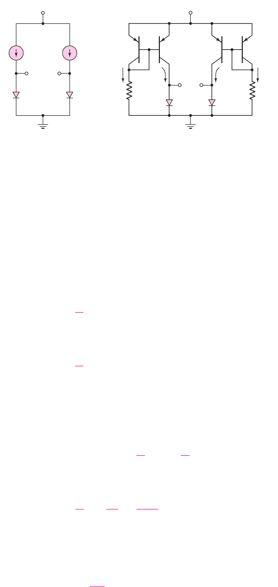
666 Part 2 Analog Electronics
described and analyzed in Chapter 5. The two diodes,
D
1
and
D
2
, are assumed to be
matched or identical devices. We also assume that all transistors are matched. Ne-
glecting base currents, we have
I
1
= I
REF1
and
I
2
= I
REF2
.
Choices: Ideal matched silicon diodes and bipolar transistors are available. In addi-
tion, ideal op-amps are available.
Solution (Diodes): From Chapter 1, we can write the voltage drops across each
diode as
V
D1
= V
T
ln
I
1
I
S
(9.101(a))
and
V
D2
= V
T
ln
I
2
I
S
(9.101(b))
We may note that, since the two diodes are matched, the reverse-saturation current,
I
S
, is the same in the two expressions.
The output voltage is defined as the difference between the voltages across the
two diodes, or
V
AT
= V
D1
− V
D2
= V
T
ln
I
1
I
S
−ln
I
2
I
S
(9.102(a))
or
V
AT
= V
T
ln
I
1
I
2
=
kT
e
ln
I
REF 1
I
REF 2
(9.102(b))
The output voltage,
V
AT
, is now directly proportional to absolute temperature T,
hence the subscript AT.
If we let
I
REF1
/I
REF2
= 5
, then Equation (9.102(b)) can be written as
V
AT
= (0.0259)
T
300
ln(5) = (1.3895 ×10
−4
)T
(9.103)
V
D1
D
1
D
2
D
1
D
2
I
1
I
2
Q
1
R
1
I
1
I
REF1
I
2
R
2
Q
2
Q
4
Q
3
V
D2
V
AT
V
AT
V
+
V
+
+
+
–
+
–
V
D1
+
+–
–
V
D2
+
–
–
I
REF2
(a) (b)
Figure 9.48 (a) Two diodes biased with constant current sources. (b) The same circuit with
the constant current sources implemented with transistor circuits.
nea80644_ch09_619-686.qxd 6/19/09 4:26 AM Page 666 pmath DATA-DISK:Desktop Folder:18.6.09:MHDQ134-09:

Chapter 9 Ideal Operational Amplifiers and Op-Amp Circuits 667
Letting
I
REF1
/I
REF2
> 0
provides a small amount of gain. Converting absolute tem-
perature to degrees Celsius and then to degrees Fahrenheit, we find
T = T
C
+273.15
(9.104)
and
T
F
= 32 +
9
5
T
C
⇒ T
C
= (T
F
−32)
5
9
(9.105)
where
T
C
and
T
F
are temperatures in degrees Celsius and degrees Fahrenheit,
respectively.
Combining Equations (9.104) and (9.105), we obtain
T = (T
F
−32)
5
9
+273.15 =
5
9
T
F
+255.37
(9.106)
The output voltage from Equation (9.103) can now be written as
V
AT
= (1.3895 ×10
−4
)
5
9
T
F
+255.37
= (7.719 ×10
−5
)T
F
+3.5484 ×10
−2
(9.107)
Solution (Instrumentation Amplifier): Since neither terminal of the output voltage
is at ground potential, we can apply this voltage to an instrumentation amplifier to
obtain a voltage gain. The output of the instrumentation amplifier will be applied to a
summing amplifier in addition to an offset voltage. The objective of the design is to
obtain an output voltage of zero volts at
T
F
= 0
and an output voltage of 5 V at
T
F
= 100
◦
F
.
If the gain of the instrumentation amplifier is
A =−129.55
, then the output of
the instrumentation amplifier is as follows:
Solution (Output Stage): The offset voltage can be generated by using the nonin-
verting op-amp circuit with a Zener diode, as shown in Figure 9.49. If we use a Zener
diode with a breakdown voltage of 3.60 V and if we set
R
3
/R
4
= 0.277
, then the
output voltage is
V
O2
=+4.597 V
. Applying the output voltage of the instrumenta-
tion amplifier,
V
O1
, and the offset voltage,
V
O2
, to a summing amplifier with a gain
of
−5
as shown in Figure 9.49, we achieve the desired specifications. That is
V
O
= 0
at
T
F
= 0
and
V
O
= 5V
at
T
F
= 100
◦
F
.
Comment: The primary advantage of this system is that the output voltage is a lin-
ear function of temperature.
In Chapter 16, we can apply the analog output voltage
V
O
to an A/D converter
and use a seven-segment display so that the output signal is actually displayed in
terms of degrees Fahrenheit.
T
F
V
AT
V
O1
0 0.035484
−4.5970
100 0.043203
−5.5970
nea80644_ch09_619-686.qxd 6/19/09 4:26 AM Page 667 pmath DATA-DISK:Desktop Folder:18.6.09:MHDQ134-09: