Neamen D. Microelectronics: Circuit Analysis and Design
Подождите немного. Документ загружается.


638 Part 2 Analog Electronics
EXERCISE PROBLEM
Ex 9.4: (a) Design an inverting summing amplifier that will produce an
output voltage of
v
O
=−3(v
I1
+2v
I2
+0.3v
I3
+4v
I4
)
. The maximum resis-
tance is to be limited to 400 k
. (b) Using the results of part (a), determine
v
O
for (i)
v
I1
= 0.1V
,
v
I2
=−0.2V,v
I3
=−1V
,
v
I4
= 0.05 V;
and for
(ii)
v
I1
=−0.2V
,
v
I2
= 0.3V,v
I3
= 1.5V,v
I4
=−0.1V.
(Ans. (a) Let
R
3
= 400 k, R
F
= 360 k, R
1
= 120 k, R
2
= 60 k, R
4
= 30 k;
(b) (i)
v
O
=+1.2V,
(ii)
v
O
=−1.35 V
)
Test Your Understanding
TYU 9.4 Consider an ideal summing amplifier as shown in Figure 9.14(a) with
R
1
= 20
k
,
R
2
= 40
k
,
R
3
= 50
k
, and
R
F
= 200
k
. Determine the output
voltage
v
O
for (a)
v
I1
=−0.25 mV,v
I2
=+0.30 mV,v
I3
=−0.50 mV;
and
(b)
v
I1
=+10 mV,v
I2
=−40 mV,v
I3
=+25 mV.
(Ans. (a)
v
O
= 3mV,
(b)
v
O
= 0)
TYU 9.5 Design the summing amplifier in Figure 9.14 to produce the average (mag-
nitude) of three input voltages, i.e.,
v
O
= (v
I1
+v
I2
+v
I3
)/3
. The amplifier is to be
designed such that each input signal sees the maximum possible input resistance
under the condition that the maximum allowed resistance in the circuit is 1 M. (Ans.
R
1
= R
2
= R
3
= 1M
,
R
F
= 333 k
)
9.4 NONINVERTING AMPLIFIER
Objective: • Analyze and understand the characteristics of the non-
inverting operational amplifier, including the voltage follower or
buffer.
In our previous discussions, the feedback element was connected between the output
and the inverting terminal. However, a signal can be applied to the noninverting
terminal while still maintaining negative feedback.
Basic Amplifier
Figure 9.15 shows the basic noninverting amplifier. The input signal
v
I
is applied
directly to the noninverting terminal, while one side of resistor R
1
is connected to the
inverting terminal and the other side is at ground.
Previously, when v
2
was at ground potential, we argued that v
1
was also essen-
tially at ground potential, and we stated that terminal (1) was at virtual ground. The
same principle applies to the circuit in Figure 9.15, with slightly different terminol-
ogy. The negative feedback connection forces the terminal voltages v
1
and v
2
to be
essentially equal. Such a condition is referred to as a virtual short. This condition
exists since a change in v
2
will cause the output voltage v
O
to change in such a way
that v
1
is forced to track v
2
. The virtual short means that the voltage difference
9.4.1
nea80644_ch09_619-686.qxd 6/19/09 4:25 AM Page 638 pmath DATA-DISK:Desktop Folder:18.6.09:MHDQ134-09:
Chapter 9 Ideal Operational Amplifiers and Op-Amp Circuits 639
between v
1
and v
2
is, for all practical purposes, zero. However, unlike a true short
circuit, there is no current flow directly from one terminal to the other. We use the
virtual short concept, i.e.
v
1
= v
2
, as an ideal op-amp characteristic and use this
property in our circuit analysis.
The analysis of the noninverting amplifier is essentially the same as for the
inverting amplifier. We assume that no current enters the input terminals. Since
v
1
= v
2
, then
v
1
= v
I
, and current i
1
is given by
i
1
=−
v
1
R
1
=−
v
I
R
1
(9.31)
Current i
2
is given by
i
2
=
v
1
−v
O
R
2
=
v
I
−v
O
R
2
(9.32)
As before,
i
1
= i
2
, so that
−
v
I
R
1
=
v
I
−v
O
R
2
(9.33)
Solving for the closed-loop voltage gain, we find
A
v
=
v
O
v
I
= 1 +
R
2
R
1
(9.34)
From this equation, we see that the output is in phase with the input, as expected.
Also note that the gain is always greater than unity.
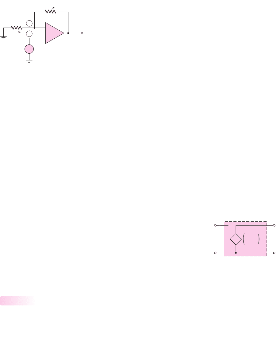
The input signal
v
I
is connected directly to the noninverting terminal; therefore,
since the input current is essentially zero, the input impedance seen by the source is
very large, ideally infinite. The ideal equivalent circuit of the noninverting op-amp is
shown in Figure 9.16.
Voltage Follower
An interesting property of the noninverting op-amp occurs when
R
1
=∞
, an open
circuit. The closed-loop gain then becomes
A
v
=
v
O
v
I
= 1
(9.35)
Since the output voltage follows the input, this op-amp circuit is called a voltage
follower. The closed-loop gain is independent of resistor R
2
(except when
R
2
=∞
),
so we can set
R
2
= 0
to create a short circuit.
9.4.2
1
2
R
1
R
2
i
2
v
O
v
I
i
1
v
1
v
2
–
+
+
–
Figure 9.15 Noninverting op-amp circuit
–
+
–
+
R
2
R
1
1 + v
I
v
I
v
O
+
–
Figure 9.16 Equivalent
circuit of ideal noninverting
op-amp
nea80644_ch09_619-686.qxd 6/19/09 4:25 AM Page 639 pmath DATA-DISK:Desktop Folder:18.6.09:MHDQ134-09:
640 Part 2 Analog Electronics
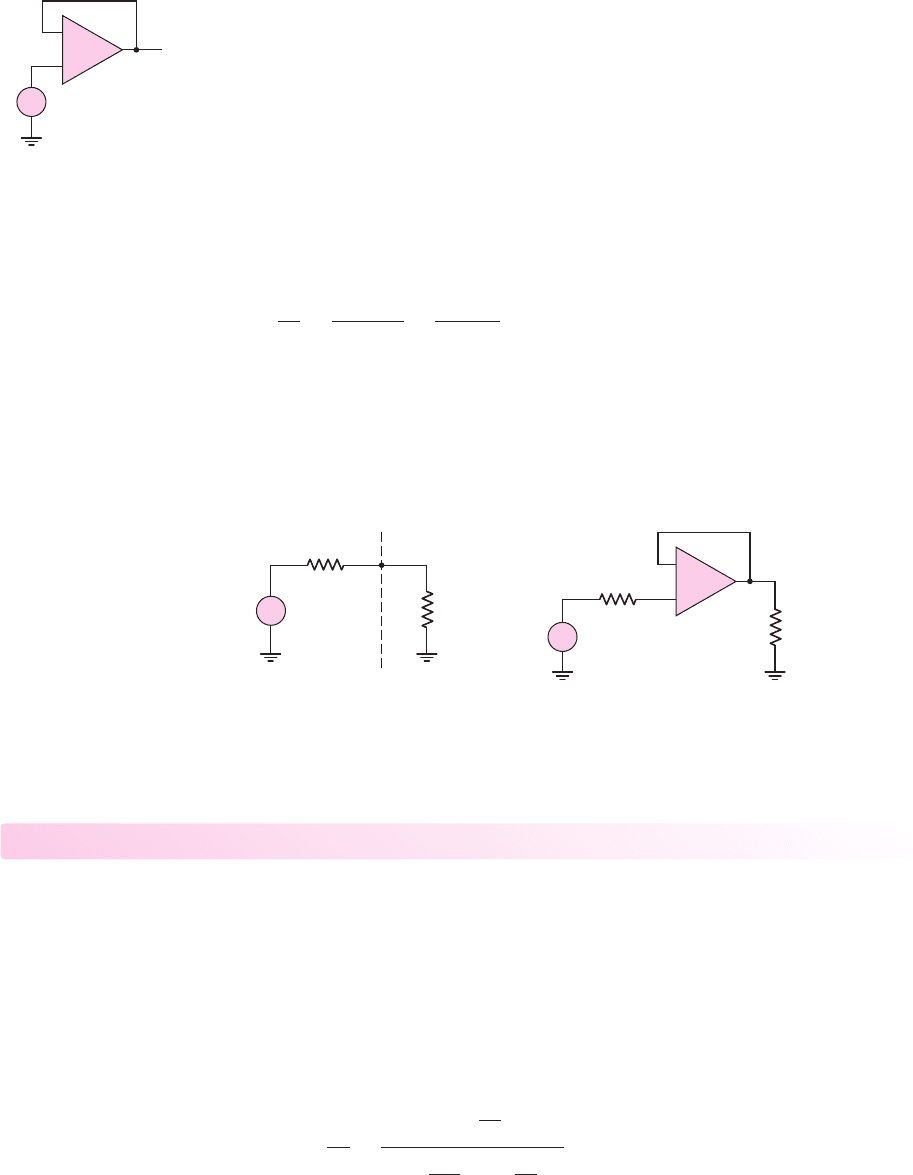
The voltage-follower op-amp circuit is shown in Figure 9.17. At first glance, it
might seem that this circuit, with unity voltage gain, would be of little value. However,
other terms used for the voltage follower are impedance transformer or buffer. The
input impedance is essentially infinite, and the output impedance is essentially zero. If,
for example, the output impedance of a signal source is large, a voltage follower in-
serted between the source and a load will prevent loading effects, that is, it will act as a
buffer between the source and the load.
Consider the case of a voltage source with a 100 k
output impedance driving a
1 k
load impedance, as shown in Figure 9.18(a). This situation may occur if the
source is a transducer. (We will see an example of this later in the chapter when we
consider a temperature-sensitive resistor, or thermistor, in a bridge circuit.) The ratio
of output voltage to input voltage is
v
O
v
I
=
R
L
R
L
+ R
S
=
1
1 + 100
∼
=
0.01
This equation indicates that, for this case, there is a severe loading effect, or attenu-
ation, in the signal voltage.
Figure 9.18(b) shows a voltage follower inserted between the source and the
load. Since the input impedance to the noninverting terminal is usually much greater
than 100 k
, then
v
O
∼
=
v
I
and the loading effect is eliminated.
+
–
R
L
= 1 kΩ
R
S
= 100 kΩ
Source Load
+
–
R
L
= 1 kΩ
R
S
= 100 kΩ
+
–
(
a
)(
b
)
v
O
v
I
v
O
v
I
+
–
+
–
–
+
Figure 9.18 (a) Source with a 100 k
output resistance driving a 1 k
load and (b) source
with a 100 k
output resistance, voltage follower, and 1 k
load
v
O
v
I
+
–
–
+
Figure 9.17 Voltage-
follower op-amp
Test Your Understanding
TYU 9.6 (a) Design a noninverting amplifier such that the closed-loop gain is
A
v
= 10
. The maximum resistance is to be 180 k
and the output voltage is to be
in the range
−9 ≤ v
O
≤+9
V. (b) Repeat part (a) for a closed-loop gain of
A
v
= 5
.
The maximum current in any resistor is to be limited to
100 μ
A when the output
voltage is in the range
−5 ≤ v
O
≤+5V
. (Ans. (a)
R
2
= 180 k
,
R
1
= 20 k
;
(b)
R
2
= 40 k
,
R
1
= 10 k)
TYU 9.7 The noninverting op-amp in Figure 9.15 has a finite differential gain of A
od
.
Show that the closed-loop gain is
A
v
=
v
O
v
I
=
1 +
R
2
R
1
1 +
1
A
od
1 +
R
2
R
1
nea80644_ch09_619-686.qxd 6/19/09 4:25 AM Page 640 pmath DATA-DISK:Desktop Folder:18.6.09:MHDQ134-09:
Chapter 9 Ideal Operational Amplifiers and Op-Amp Circuits 641
9.5 OP-AMP APPLICATIONS
Objective: • Analyze several ideal op-amp circuits including the
difference amplifier and the instrumentation amplifier.
The summing amplifier is one example of special functional capabilities that can be
provided by the op-amp. In this section, we will look at other examples of op-amp
versatility.
Current-to-Voltage Converter
In some situations, the output of a device or circuit is a current. An example is the
output of a photodiode or photodetector. We may need to convert this output current
to an output voltage.
Consider the circuit in Figure 9.20. The input resistance R
i
at the virtual ground
node is
R
i
=
v
1
i
1
∼
=
0
(9.36)
In most cases, we can assume that
R
S
R
i
; therefore, current i
1
is essentially equal
to the signal current i
S
. Then,
i
2
= i
1
= i
S
(9.37)
and
v
O
=−i
2
R
F
=−i
S
R
F
(9.38)
9.5.1
R
1
= 5 kΩ
R
2
= 70 kΩ
R
b
= 50 kΩ
R
a
= 25 kΩ
v
O
v
I1
v
I2
–
+
Figure 9.19 Figure for Exercise TYU 9.8
–
+
R
S
R
F
i
v
O
v
1
= 0
i
S
0
V
–
R
i
i
2
i
1
Figure 9.20 Current-to-voltage converter
TYU 9.8 Use superposition to determine the output voltage
v
O
in the ideal op-amp
circuit in Figure 9.19. (Ans.
v
O
= 10v
I1
+5v
I2
)
nea80644_ch09_619-686.qxd 6/19/09 4:25 AM Page 641 pmath DATA-DISK:Desktop Folder:18.6.09:MHDQ134-09:
642 Part 2 Analog Electronics
The output voltage is directly proportional to the signal current, and the feedback re-
sistance R
F
is the magnitude of the ratio of the output voltage to the signal current.
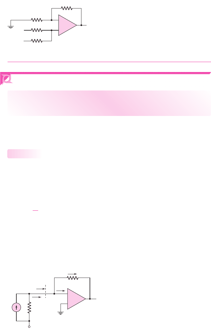
Voltage-to-Current Converter
The complement of the current-to-voltage converter is the voltage-to-current con-
verter. For example, we may want to drive a coil in a magnetic circuit with a given
current, using a voltage source. We could use the inverting op-amp shown in Figure
9.21. For this circuit,
i
2
= i
1
=
v
I
R
1
(9.39)
which means that current i
2
is directly proportional to input voltage v
I
and is inde-
pendent of the load impedance or resistance R
2
. However, one side of the load device
might need to be at ground potential, so the circuit in Figure 9.21 would not be prac-
tical for such applications.
9.5.2
R
1
R
2
–
+
i
2
v
O
v
I
i
1
v
1
= 0
0
Figure 9.21 Simple voltage-to-current converter
R
1
R
F
–
+
R
3
R
2
Z
L
+
–
i
2
v
O
v
I
i
L
v
L
i
1
i
3
i
4
v
1
v
2
0
0
0
Figure 9.22 Voltage-to-current converter
Consider the circuit in Figure 9.22. In this case, one terminal of the load device,
which has an impedance of Z
L
, is at ground potential. The inverting terminal (1) is
not at virtual ground. From the virtual short concept,
v
1
= v
2
. We also note that
v
1
= v
2
= v
L
= i
L
Z
L
. Equating the currents i
1
and i
2
, we have
v
I
−i
L
Z
L
R
1
=
i
L
Z
L
−v
O
R
F
(9.40)
Summing the currents at the noninverting terminal gives
v
O
−i
L
Z
L
R
3
= i
L
+
i
L
Z
L
R
2
(9.41)
Solving for (
v
O
−i
L
Z
L
) from Equation (9.40) and substituting into Equation (9.41)
produces
R
F
R
1
·
(i
L
Z
L
−v
I
)
R
3
= i
L
+
i
L
Z
L
R
2
(9.42)
nea80644_ch09_619-686.qxd 6/19/09 4:25 AM Page 642 pmath DATA-DISK:Desktop Folder:18.6.09:MHDQ134-09:

Chapter 9 Ideal Operational Amplifiers and Op-Amp Circuits 643
Combining terms in i
L
, we obtain
i
L
R
F
Z
L
R
1
R
3
−1 −
Z
L
R
2
= v
I
R
F
R
1
R
3
(9.43)
In order to make i
L
independent of Z
L
, we can design the circuit such that the coeffi-
cient of Z
L
is zero, or
R
F
R
1
R
3
=
1
R
2
(9.44)
Equation (9.43) then reduces to
i
L
=−v
I
R
F
R
1
R
3
=
−v
I
R
2
(9.45)
which means that the load current is proportional to the input voltage and is inde-
pendent of the load impedance Z
L
, as long as the output voltage remains between
allowed limits.
We may note that the input resistance seen by the source v
I
is finite, and is actu-
ally a function of the load impedance Z
L
. For a constant i
L
, a change in Z
L
produces
a change in
v
L
= v
2
= v
1
, which causes a change in i
1
. A voltage follower may be
inserted between the voltage source
v
I
and the resistor R
1
to eliminate any loading
effects due to a variable input resistance.
EXAMPLE 9.5
Objective: Determine a load current in a voltage-to-current converter.
Consider the circuit in Figure 9.22. Let
Z
L
= 100
,
R
1
= 10 k
,
R
2
= 1k
,
R
3
= 1k
, and
R
F
= 10 k
. If
v
I
=−5
V, determine the load current i
L
and the
output voltage v
O
.
Solution: We note first that the condition expressed by Equation (9.44) is satisfied;
that is,
1
R
2
=
R
F
R
1
R
3
=
10
(10)(1)
→
1
1
The load current is
i
L
=
−v
I
R
2
=
−(−5)
1k
= 5mA
and the voltage across the load is
v
L
= i
L
Z
L
= (5 ×10
−3
)(100) = 0.5V
Currents i
4
and i
3
are
i
4
=
v
L
R
2
=
0.5
1
= 0.5mA
and
i
3
= i
4
+i
L
= 0.5 +5 = 5.5mA
nea80644_ch09_619-686.qxd 6/19/09 4:25 AM Page 643 pmath DATA-DISK:Desktop Folder:18.6.09:MHDQ134-09:
644 Part 2 Analog Electronics
–
+
10
5
0
–10 –5
V
i
(V)
V
out
(V)
0
10
10 kΩ
10 kΩ
1 kΩ
1 kΩ 100 Ω
10 V
10 V
0
0
00
0
4
1
6
5
7
3
2
V
+
–
0 V
+
–
mA–741
+
–
5
0
–10 –5
V
i
(V)
I
L
(mA)
R
F
v
i
R
L
v
1
U
1
v
out
v
2
R
3
R
2
R
1
0
10
5
0 0.5
R
L
(kΩ)
V
out
(V)
1.0
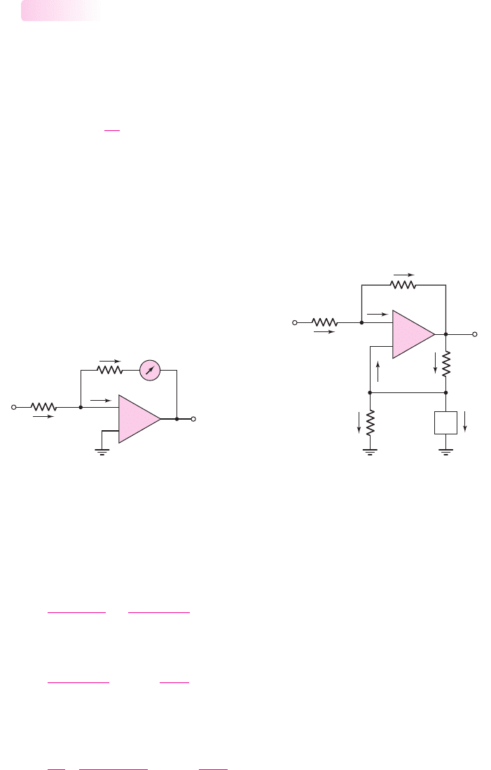
(a) (b)
(c) (d)
v–
v+
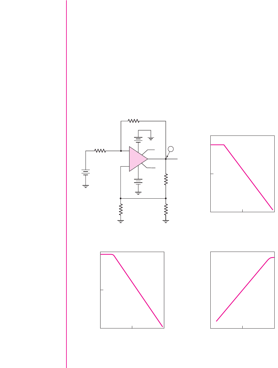
Figure 9.23 (a) PSpice circuit schematic; (b) load current and (c) op-amp output voltage
versus input voltage; (d) op-amp output voltage versus load resistance for
v
1
=−5
V
The output voltage is then
v
O
= i
3
R
3
+v
L
= (5.5 ×10
−3
)(10
3
) + 0.5 = 6V
We could also calculate i
1
and i
2
as
i
1
= i
2
=−0.55 mA
Comment: In this example, we implicitly assume that the op-amp is not in satura-
tion, which means that the applied dc bias voltage must be greater than 6 V. In
addition, since currents i
2
(which is negative) and i
3
must be supplied by the op-amp,
we are assuming that the op-amp is capable of supplying 6.05 mA.
Computer Verification: The PSpice circuit schematic of the voltage-to-current
converter is shown in Figure 9.23(a). The input voltage was varied between 0 and
−10
V. Figure 9.23(b) shows the current through the 100
load and Figure 9.23(c)
nea80644_ch09_619-686.qxd 6/19/09 4:25 AM Page 644 pmath DATA-DISK:Desktop Folder:18.6.09:MHDQ134-09:
Chapter 9 Ideal Operational Amplifiers and Op-Amp Circuits 645
shows the op-amp output voltage as a function of the input voltage. At approximately
v
I
=−7.5
V, the op-amp saturates, so the load current and output voltage no longer
increase with input voltage. This result demonstrates that the ideal voltage-to-current
conversion is valid only if the op-amp is operating in its linear region. Figure 9.23(d)
shows the output voltage as a function of load resistance for an input voltage of
v
I
=−5
V. At a load resistance greater than approximately 900
, the op-amp
saturates. The range over which the op-amp remains linear could be increased by
increasing the bias to
±15
V, for example.
EXERCISE PROBLEM
Ex 9.5: Consider the voltage-to-current converter shown in Figure 9.22. The load
impedance is
Z
L
= 200
and the input voltage is
v
I
=−3
V. Determine i
L
and
v
O
if
R
1
= 10 k
,
R
2
= 1.5k
,
R
3
= 3k
, and
R
F
= 20 k
. (Ans.
i
L
= 2
mA,
v
O
= 7.2
V)
Difference Amplifier
An ideal difference amplifier amplifies only the difference between two signals; it re-
jects any common signals to the two input terminals. For example, a microphone sys-
tem amplifies an audio signal applied to one terminal of a difference amplifier, and
rejects any 60 Hz noise signal or “hum” existing on both terminals. The basic op-amp
also amplifies the difference between two input signals. However, we would like to
make a difference amplifier, in which the output is a function of the ratio of resistors,
as we had for the inverting and noninverting amplifiers.
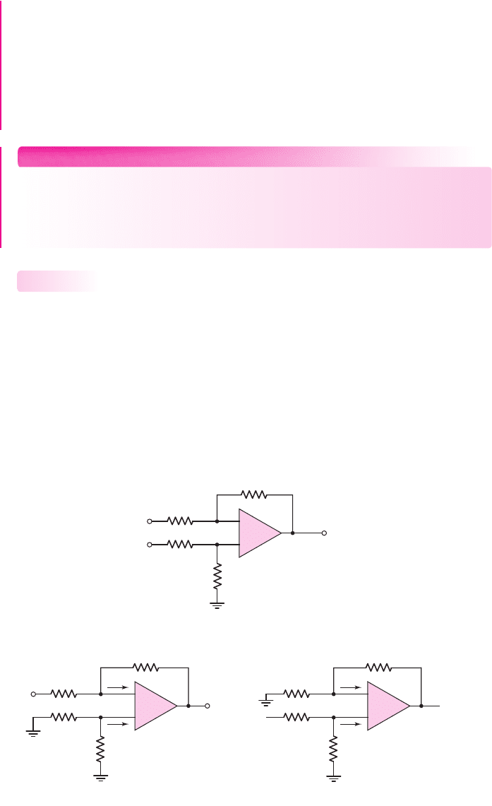
Consider the circuit shown in Figure 9.24(a), with inputs
v
I1
and
v
I2
. To analyze
the circuit, we will use superposition and the virtual short concept. Figure 9.24(b)
9.5.3
R
1
R
2
R
3
–
+
R
4
R
1
R
2
R
3
–
+
R
4
R
1
R
2
R
3
–
+
R
4
(a)
(b) (c)
v
O
v
I1
v
I2
v
O1
v
I1
v
1a
v
2a
0
0
v
O2
v
I2
v
1b
v
2b
0
0
Figure 9.24 (a) Op-amp difference amplifier, (b) difference amplifier with
v
I2
= 0
and
(c) difference amplifier with
v
I1
= 0
nea80644_ch09_619-686.qxd 6/19/09 4:25 AM Page 645 pmath DATA-DISK:Desktop Folder:18.6.09:MHDQ134-09:

646 Part 2 Analog Electronics
shows the circuit with input
v
I2
= 0
. There are no currents in R
3
and R
4
; therefore,
v
2a
= 0
. The resulting circuit is the inverting amplifier previously considered, for
which
v
O1
=−
R
2
R
1
v
I1
(9.46)
Figure 9.24(c) shows the circuit with
v
I1
= 0
. Since the current into the op-amp
is zero, R
3
and R
4
form a voltage divider. Therefore,
v
2b
=
R
4
R
3
+ R
4
v
I2
(9.47)
From the virtual short concept,
v
1b
= v
2b
and the circuit becomes a noninverting
amplifier, for which
v
O2
=
1 +
R
2
R
1
v
1b
=
1 +
R
2
R
1
v
2b
(9.48)
Substituting Equation (9.47) into (9.48), we obtain
v
O2
=
1 +
R
2
R
1
R
4
R
3
+ R
4
v
I2
(9.49(a))
which can be rearranged as follows:
v
O2
= (1 + R
2
/R
1
)
R
4
/R
3
1 + R
4
/R
3
v
I2
(9.49(b))
Since the net output voltage is the sum of the individual terms, we have
v
O
= v
O1
+v
O2
(9.50(a))
or
v
O
=
1 +
R
2
R
1
⎛
⎜
⎜
⎝
R
4
R
3
1 +
R
4
R
3
⎞
⎟
⎟
⎠
v
I2
−
R
2
R
1
v
I1
(9.50(b))
A property of the ideal difference amplifier is that the output voltage is zero
when
v
I1
= v
I2
. An inspection of Equation (9.50(b)) shows that this condition is
met if
R
4
R
3
=
R
2
R
1
(9.51)
The output voltage is then
v
O
=
R
2
R
1
(v
I2
−v
I1
)
(9.52)
which indicates that this amplifier has a differential gain of
A
d
= R
2
/R
1
. This factor
is a closed-loop differential gain, rather than the open-loop differential gain A
od
of
the op-amp itself.
As previously stated, another important characteristic of electronic circuits is the
input resistance. The differential input resistance of the differential amplifier can
be determined by using the circuit shown in Figure 9.25. In the figure, we have
nea80644_ch09_619-686.qxd 6/19/09 4:25 AM Page 646 pmath DATA-DISK:Desktop Folder:18.6.09:MHDQ134-09:

Chapter 9 Ideal Operational Amplifiers and Op-Amp Circuits 647
imposed the condition given in Equation (9.51) and have set
R
1
= R
3
and
R
2
= R
4
.
The input resistance is then defined as
R
i
=
v
I
i
(9.53)
Taking into account the virtual short concept, we can write a loop equation, as
follows:
v
I
= iR
1
+iR
1
= i(2R
1
)
(9.54)
Therefore, the input resistance is
R
i
= 2R
1
(9.55)
DESIGN EXAMPLE 9.6
Objective: Design a difference amplifier with a specified gain.
Specifications: Design the difference amplifier with the configuration shown in Fig-
ure 9.24 such that the differential gain is 30. Standard valued resistors are to be used
and the maximum resistor value is to be 500 k
.
Choices: An ideal op-amp is available.
Solution: The differential gain is given by
R
2
R
1
=
R
4
R
3
= 30
From Appendix C, we can use standard resistors of
R
2
= R
4
= 390 k and R
1
= R
3
= 13 k
These resistor values are obviously less than 500 k
and will give an input resistance
of
R
i
= 2R
1
= 2(13) = 26 k
.
Trade-offs: Resistor tolerances must be considered as we have in other designs. This
effect is considered in end-of-chapter Problem 9.62. Resistor tolerances also affect
the common-mode rejection ratio, as analyzed in the following example.
Comment: This example illustrated one disadvantage of this differential amplifier
design. It cannot achieve both high gain and high input impedance without using
extremely large resistor values.
R
1
R
1
R
2
–
+
R
2
+
–
v
O
v
I
i
i
Virtual
short
circuit
R
i
–
+
–
+
Figure 9.25 Circuit for measuring differential input resistance of op-amp difference
amplifier
nea80644_ch09_619-686.qxd 6/19/09 4:25 AM Page 647 pmath DATA-DISK:Desktop Folder:18.6.09:MHDQ134-09: