Neamen D. Microelectronics: Circuit Analysis and Design
Подождите немного. Документ загружается.


I
x
R
i
+
–
V
x
R
o
R
of
=
V
x
I
x
b
i
I
o
= b
i
I
x
A
i
I
e
I
e
I
fb
I
i
= 0
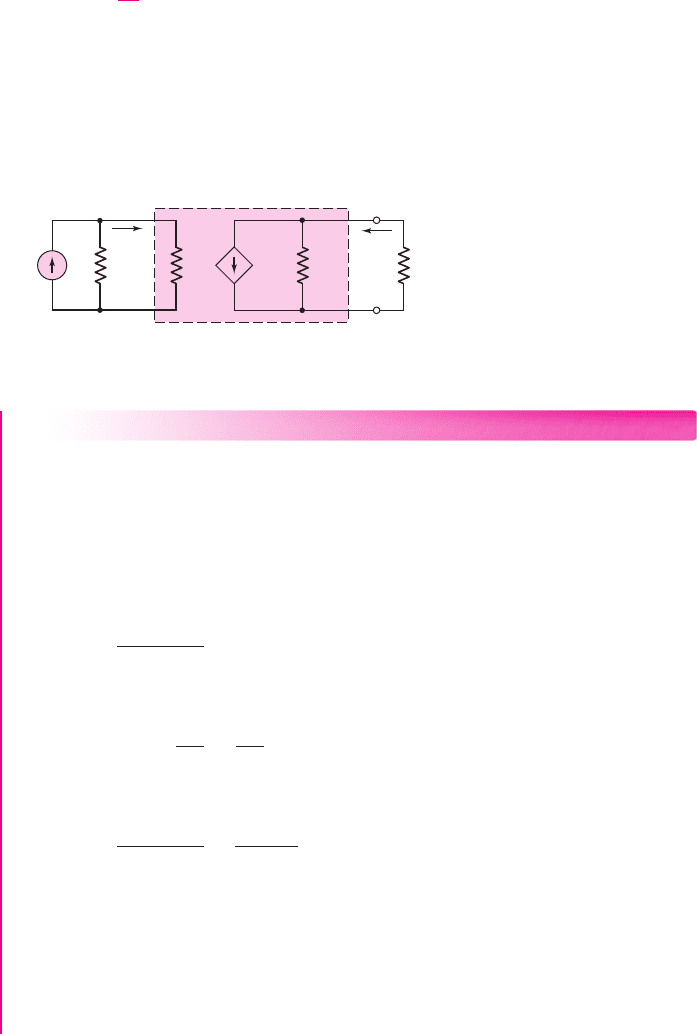
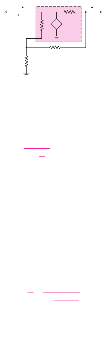
Figure 12.10 Ideal shunt–series feedback configuration for determining output resistance
The form of the equation for the current transfer function of the current ampli-
fier (shunt–series connection) is the same as that for the voltage transfer function of
the voltage amplifier (series–shunt connection). We will show that this will be the
same for the two feedback connections yet to be discussed.
The input resistance of the shunt–series configuration is
R
if
. Starting with Equa-
tion (12.31), using Equations (12.29) and (12.30), we find that
I
i
= I
ε
+ I
fb
= I
ε
+β
i
I
o
= I
ε
+β
i
(A
i
I
ε
)
(12.33(a))
or
I
ε
=
I
i
(1 + β
i
A
i
)
(12.33(b))
The input voltage is
V
i
= I
ε
R
i
=
I
i
R
i
(1 + β
i
A
i
)
(12.34)
The input resistance with feedback is then
R
if
=
V
i
I
i
=
R
i
(1 + β
i
A
i
)
(12.35)
Equation (12.35) shows that a shunt input connection decreases the input resistance
compared to that of the basic amplifier. A small input resistance is a desirable property
of a current amplifier, to avoid loading effects on the input signal current source.
The output resistance of the feedback circuit can be determined from the equiv-
alent circuit in Figure 12.10. The input signal current is set equal to zero (an open
circuit) and a test current is applied to the output terminals. Since the input signal
current source is assumed to be ideal we have
R
S
=∞
.
868 Part 2 Analog Electronics
From the circuit, we see that
I
ε
+ I
fb
= I
ε
+β
i
I
x
= 0
(12.36(a))
or
I
ε
=−β
i
I
x
(12.36(b))
nea80644_ch12_851-946.qxd 6/23/09 1:45 PM Page 868 pmath DATA-DISK:Desktop Folder:23/06/09:MHDQ134-12:
I
i
R
S
R
of
R
L
R
if
A
if
I
i
′
I
o
I
i
'
Figure 12.11 Equivalent circuit of shunt–series feedback circuit, or current amplifier
The output voltage can be written as
V
x
= (I
x
− A
i
I
ε
)R
o
= [I
x
− A
i
(−β
i
I
x
)]R
o
= I
x
(1 + β
i
A
i
)R
o
(12.37)
Therefore,
R
of
=
V
x
I
x
= (1 +β
i
A
i
)R
o
(12.38)
Equation (12.38) shows that a series output connection increases the output
resistance compared to that of the basic amplifier. A large output resistance is a
desirable property of a current amplifier, to avoid loading effects on the output signal
due to a load connected to the amplifier output.
The equivalent circuit of this feedback current amplifier is shown in Figure 12.11.
Chapter 12 Feedback and Stability 869
EXAMPLE 12.6
Objective: Determine the input resistance of a shunt input connection and the out-
put resistance of a series output connection, for a feedback current amplifier.
Consider a shunt–series feedback amplifier in which the open-loop gain is
A
i
= 10
5
and the closed-loop gain is
A
if
= 50
. Assume the input and output resis-
tances of the basic amplifier are
R
i
= 10 k
and
R
o
= 20 k
, respectively.
Solution: The ideal closed-loop current transfer function, from Equation (12.32), is
A
if
=
A
i
(1 + β
i
A
i
)
or
(1 + β
i
A
i
) =
A
i
A
if
=
10
5
50
= 2 ×10
3
From Equation (12.35), the input resistance is
R
if
=
R
i
(1 + β
i
A
i
)
=
10
2 × 10
3
k ⇒ 5
and from Equation (12.38), the output resistance is
R
of
= (1 +β
i
A
i
)R
o
= (2 ×10
3
)(20) k ⇒ 40 M
Comment: With a shunt input connection, the input resistance decreases drastically,
and with a series output connection, the output resistance increases substantially,
assuming negative feedback. These are the desired characteristics of a current amplifier.
nea80644_ch12_851-946.qxd 6/23/09 1:45 PM Page 869 pmath DATA-DISK:Desktop Folder:23/06/09:MHDQ134-12:
A
g
V
e
I
o
R
i
+
–
V
e
+
–
V
fb
b
z
I
o
R
if
R
of
R
o
V
i
R
S
I
i
+
–
+
–
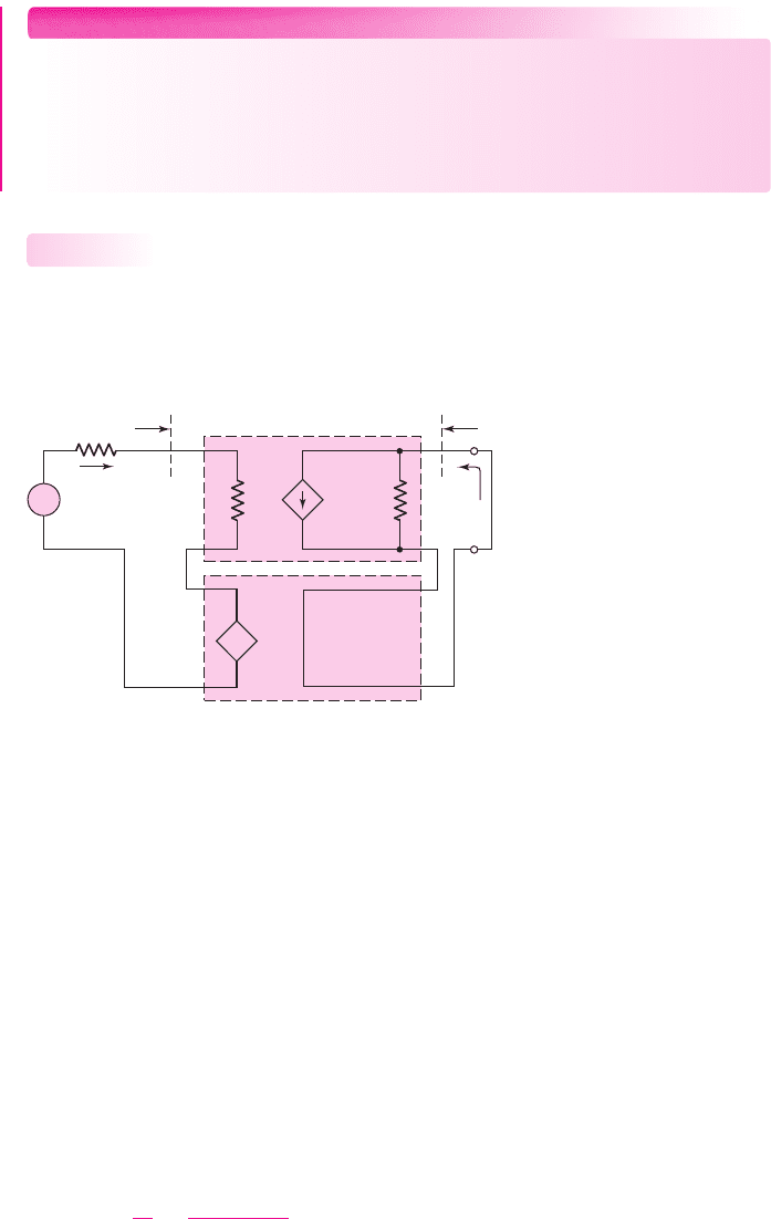
Figure 12.12 Ideal series–series feedback topology
EXERCISE PROBLEM
Ex 12.6: Consider the ideal shunt–series feedback amplifier in Figure 12.9.
Assume that the source resistance is
R
S
=∞
. (a) If
I
i
= 100 μA
,
I
fb
= 99 μA
,
and
I
o
= 5
mA, determine A
i
,
β
i
, and
A
if
, including units. (b) Using the results of
part (a), determine
R
if
and
R
of
, for
R
i
= 5k
and
R
o
= 4k
. (Ans. (a)
A
i
=
5000
A/A,
β
i
= 0.0198
A/A,
A
if
= 50
A/A (b)
R
if
= 50
,
R
of
= 400 k
)
Series–Series Configuration
The configuration of an ideal series–series feedback amplifier is shown in Figure 12.12.
The feedback samples a portion of the output current and converts it to a voltage. This
feedback circuit can therefore be thought of as a voltage-to-current amplifier.
12.3.3
870 Part 2 Analog Electronics
The circuit consists of a basic amplifier that converts the error voltage to an
output current with a gain factor A
g
and that has an input resistance
R
i
. The feedback
circuit samples the output current and produces a feedback voltage
V
fb
,
which is in
series with the input signal voltage V
i
.
Assuming the output is essentially a short circuit, the output current is
I
o
= A
g
V
ε
and the feedback voltage is
V
fb
= β
z
I
o
where
β
z
is called a resistance feedback transfer function, with units of resistance.
The input signal voltage, neglecting the effect of R
S
, is
V
i
= V
ε
+ V
fb
Combining these equations, as we have in previous analyses, yields the closed-loop
current-to-voltage transfer function,
A
gf
=
I
o
V
i
=
A
g
(1 + β
z
A
g
)
(12.39)
The units of the transfer function given by Equation (12.39) are amperes/volt, or
conductance. We may note that the term
β
z
A
g
is dimensionless. This particular feed-
back circuit is therefore called a transconductance amplifier.
nea80644_ch12_851-946.qxd 6/23/09 1:45 PM Page 870 pmath DATA-DISK:Desktop Folder:23/06/09:MHDQ134-12:
I
i
R
S
R
i
I
e
I
fb
+
–
V
i
b
g
V
o
R
if
A
z
I
e
R
o
+
–
V
o
R
of
+
–
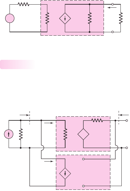
Figure 12.14 Ideal shunt–shunt feedback topology
+
–
V
i
R
S
A
gf
V
i
′
R
if
R
L
R
of
I
o
+
–
V
i
′
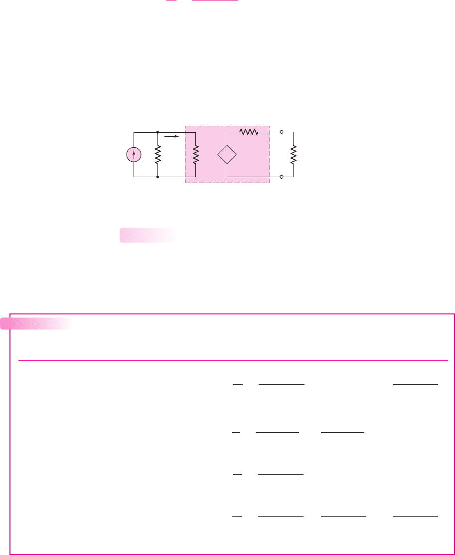
Figure 12.13 Equivalent circuit of series–series feedback circuit, or transconductance amplifier
The input and output resistances are a function of the specific types of input and
output connections, respectively. The input resistance for the series connection is
given by Equation (12.25), which shows that with this configuration, the input resis-
tance increases compared to that of the basic amplifier. The output resistance for the
series connection is given by Equation (12.38), which shows that with this configu-
ration, the output resistance increases compared to that of the basic amplifier. The
equivalent circuit for the series–series feedback amplifier is shown in Figure 12.13.
Chapter 12 Feedback and Stability 871
Shunt–Shunt Configuration
The configuration of the ideal shunt–shunt feedback amplifier is shown in Figure 12.14.
The feedback samples a portion of the output voltage and converts it to a current. This
feedback circuit can therefore be thought of as a current-to-voltage amplifier.
12.3.4
The circuit consists of a basic amplifier that converts the error current to an out-
put voltage with a gain factor A
z
and that has an input resistance
R
i
. The feedback
circuit samples the output voltage and produces a feedback current
I
fb
, which is in
shunt with the input signal current I
i
.
Assuming the output is essentially an open circuit, the output voltage is
V
o
= A
z
I
ε
and the feedback current is
I
fb
= β
g
V
o
where
β
g
is the conductance feedback transfer function, with units of conductance.
The input signal current, assuming R
S
is very large, is
I
i
= I
ε
+ I
fb
nea80644_ch12_851-946.qxd 6/23/09 1:45 PM Page 871 pmath DATA-DISK:Desktop Folder:23/06/09:MHDQ134-12:
A
zf
I
i
′
R
of
R
if
V
o
+
–
+
–
R
L
I
i
R
S
I
i
′
+
–
Figure 12.15 Equivalent circuit of shunt–shunt feedback circuit or, transresistance amplifier
Table 12.1 Summary results of feedback amplifier functions for the ideal feedback circuit
Feedback Source Output Transfer Input Output
amplifier signal signal function resistance resistance
Series–shunt Voltage Voltage
A
v f
=
V
o
V
i
=
A
v
(1 + β
v
A
v
)
R
i
(1 + β
v
A
v
)
R
o
(1 + β
v
A
v
)
(voltage
amplifier)
Shunt–series Current Current
A
if
=
I
o
I
i
=
A
i
(1 + β
i
A
i
)
R
i
(1 + β
i
A
i
)
R
o
(1 + β
i
A
i
)
(current
amplifier)
Series–series Voltage Current
A
gf
=
I
o
V
i
=
A
g
(1 + β
z
A
g
)
R
i
(1 + β
z
A
g
)
R
o
(1 + β
z
A
g
)
(transconductance
amplifier)
Shunt–shunt Current Voltage
A
zf
=
V
o
I
i
=
A
z
(1 + β
g
A
z
)
R
i
(1 + β
g
A
z
)
R
o
(1 + β
g
A
z
)
(transresistance
amplifier)
Combining these equations yields the closed-loop voltage-to-current transfer
function,
A
zf
=
V
o
I
i
=
A
z
(1 + β
g
A
z
)
(12.40)
The units of the transfer function given by Equation (12.40) are volts/ampere, or
resistance. We may note that the term
β
g
A
z
is dimensionless. This particular feed-
back circuit is therefore referred to as a transresistance amplifier.
The input and output resistances are again a function of only the types of input
and output connections, respectively. The input resistance is given by Equation
(12.35) and the output resistance is given by Equation (12.28). The equivalent circuit
for the shunt–shunt feedback amplifier is shown in Figure 12.15.
872 Part 2 Analog Electronics
Summary of Results
Table 12.1 summarizes the ideal relationships, including the transfer functions, input
resistances, and output resistances, obtained in the analysis of the four types of feed-
back amplifiers.
12.3.5
nea80644_ch12_851-946.qxd 6/23/09 1:45 PM Page 872 pmath DATA-DISK:Desktop Folder:23/06/09:MHDQ134-12:

Having analyzed the characteristics of the four ideal feedback topologies, we
will next derive the transfer functions and resistance characteristics of op-amp and
discrete transistor representations of each type of feedback configuration. We will
compare actual results with the ideal results, discussing any deviations from the ideal.
Test Your Understanding
TYU 12.4 An ideal series–series feedback amplifier is shown in Figure 12.12.
Assume R
S
is negligibly small. If
V
i
= 100
mV,
V
fb
= 99
mV, and
I
o
= 5
mA,
determine A
g
,
β
z
, and
A
gf
,
including units. (Ans.
A
g
= 5
A/V,
β
z
= 19.8
V/A,
A
gf
= 50
mA/V)
TYU 12.5 Consider the ideal shunt–shunt feedback amplifier in Figure 12.14.
Assume that the source resistance is
R
S
=∞.
If
I
i
= 100 μA
,
I
fb
= 99 μA
, and
V
o
= 5
V, determine A
z
,
β
g
, and
A
zf
, including units. (Ans.
A
z
= 5 ×10
6
V/A,
β
g
= 1.98 ×10
−5
A/V,
A
zf
= 50
V/mA)
12.4 VOLTAGE (SERIES–SHUNT) AMPLIFIERS
Objective: • Analyze op-amp and discrete transistor circuit examples
of series–shunt (voltage) feedback amplifiers.
In this section, we will analyze an op-amp and a discrete circuit representation of
the series–shunt feedback configuration. Since the series–shunt circuit is a voltage
amplifier, we will derive the transfer function relating the output signal voltage to
the input signal voltage. For the ideal configuration, this function is shown in
Equation (12.22) and is
A
v f
=
A
v
(1 + β
v
A
v
)
where
A
v
is the basic amplifier voltage gain and
β
v
is the voltage feedback transfer
function. We found that, in this feedback configuration, the input resistance increases
and the output resistance decreases compared to the basic amplifier values.
Op-Amp Circuit Representation
Figure 12.16 shows a noninverting op-amp circuit, which is an example of the
series–shunt configuration. The input signal is the input voltage V
i
, the feed-back
voltage is
V
fb
, and the error signal is the voltage
V
ε
. Since the shunt output samples
the output voltage, the feedback voltage is a function of the output voltage.
In the ideal feedback circuit, the amplification factor
A
v
is very large; from
Equation (12.22), the transfer function is then
A
v f
=
V
o
V
i
∼
=
1
β
v
(12.41)
12.4.1
Chapter 12 Feedback and Stability 873
V
o
V
i
+
–
V
e
+
–
V
fb
R
2
R
1
+
–
Figure 12.16 Example of
an op-amp series–shunt
feedback circuit
nea80644_ch12_851-946.qxd 6/23/09 1:45 PM Page 873 pmath DATA-DISK:Desktop Folder:23/06/09:MHDQ134-12:
A
v
V
e
+
–
V
i
V
o
R
o
R
i
R
2
R
1
I
i
+
–
+
–
V
fb
R
if
R
of
V
e
+
–
Figure 12.17 Equivalent circuit, op-amp series–shunt feedback configuration
For the ideal noninverting op-amp amplifier, we found in Chapter 9 that
A
v f
=
V
o
V
i
=
1 +
R
2
R
1
(12.42)
Therefore, the feedback transfer function
β
v
is
β
v
=
1
1 +
R
2
R
1
(12.43)
We can take a finite amplifier gain into account by considering the equivalent
circuit in Figure 12.17. The parameter
A
v
is the open-loop voltage gain of the basic
amplifier. We can write, for
R
o
≈ 0
,
V
o
= A
v
V
ε
(12.44)
and
V
ε
= V
i
− V
fb
(12.45)
therefore,
V
o
= A
v
V
i
− V
fb
(12.46)
Assuming the input resistance R
i
is very large, the feedback voltage is given by
V
fb
∼
=
R
1
R
1
+ R
2
V
o
(12.47)
Substituting Equation (12.47) into (12.46) and rearranging terms, we obtain
A
v f
=
V
o
V
i
=
A
v
1 +
A
v
1 +
R
2
R
1
(12.48)
The voltage feedback transfer function
β
v
is given by Equation (12.43), and the
closed-loop voltage transfer function can be written
A
v f
=
A
v
(
1 + β
v
A
v
)
(12.49)
874 Part 2 Analog Electronics
nea80644_ch12_851-946.qxd 6/23/09 1:45 PM Page 874 pmath DATA-DISK:Desktop Folder:23/06/09:MHDQ134-12:

The voltage transfer function for the noninverting op-amp circuit has the same form
as that for the ideal series–shunt configuration, assuming the input resistance R
i
is
very large.
We may note in this case that the voltage gain
A
v
of the basic amplifier is posi-
tive and that the feedback transfer function
β
v
is also positive, so that the loop gain
T = β
v
A
v
is positive for negative feedback.
We can now derive the expression for the input resistance
R
if
. We see from the
figure that
V
ε
= I
i
R
i
,
V
o
= A
v
V
ε
, and
V
i
= V
ε
+ V
fb
. The approximate feedback
voltage is given by Equation (12.47). Therefore, the input voltage is
V
i
= V
ε
+
R
1
R
1
+ R
2
V
o
= V
ε
+
A
v
V
ε
1 +
R
2
R
1
= V
ε
1 +
A
v
(1 + R
2
/R
1
)
(12.50)
The input resistance is then
R
if
=
V
i
I
i
=
V
i
(V
ε
/R
i
)
= R
i
1 +
A
v
(1 + (R
2
/R
1
))
= R
i
(1 + β
v
A
v
)
(12.51)
The expression for the input resistance for the op-amp circuit has the same form
as that for the ideal series input connection, as given in Equation (12.25). In the
ideal case in which the gain is
A
v
=∞
, the input resistance of the noninverting
op-amp is also infinite. However, if the gain is finite, the input resistance will also
be finite.
EXAMPLE 12.7
Objective: Determine the expected input resistance of the noninverting op-amp
circuit.
Consider the noninverting op-amp in Figure 12.16, with parameters
R
i
= 50 k
,
R
1
= 10 k
,
R
2
= 90 k
, and
A
v
= 10
4
.
Solution: The feedback transfer function
β
v
is
β
v
=
1
1 +
R
2
R
1
=
1
1 +
90
10
= 0.10
The input resistance is therefore
R
if
= R
i
(1 + β
v
A
v
) = (50)[1 +(0.10)(10
4
)]
or
R
if
∼
=
50 × 10
3
k = 50 M
Comment: Even with a moderate differential input resistance R
i
to the op-amp, the
closed-loop input resistance
R
if
is very large, because of the series input feedback
connection.
Chapter 12 Feedback and Stability 875
nea80644_ch12_851-946.qxd 6/23/09 1:45 PM Page 875 pmath DATA-DISK:Desktop Folder:23/06/09:MHDQ134-12:

+
–
+
–
R
E
V
CC
v
i
v
o
v
be
v
fb
+
–
+
–
R
S
V
DD
v
i
v
o
v
gs
v
fb
R
if
R
of
+
–
V
p
+
–
V
i
R
E
+
–
V
o
r
p
R
if
g
m
V
p
R
of
(a) (b) (c)
Figure 12.18 Discrete transistor series–shunt feedback circuits: (a) emitter-follower,
(b) source-follower, and (c) small-signal equivalent circuit of emitter follower
EXERCISE PROBLEM
Ex 12.7: Consider the noninverting op-amp circuit shown in Figure 12.16, with pa-
rameters
R
1
= 15
k
,
R
2
= 60
k
, and
A
v
= 5 ×10
4
. Assume
R
i
=∞
. Let the
input signal voltage be
V
i
= 0.10
V. (a) What is the ideal voltage gain and the ideal
output voltage? (b) (i) Determine the actual closed-loop gain and the actual output
voltage. (ii) What is the error voltage
V
ε
? (c) If the open-loop gain increases by a
factor of 10, what are the values of (i) the closed-loop gain and (ii) the error volt-
age? (Ans. (a)
A
f
= 5.00
,
V
o
= 0.500
V; (b) (i)
A
f
= 4.9995
,
V
o
= 0.49995
V,
(ii)
V
ε
= 9.999 μ
V; (c) (i)
A
f
= 4.99995
, (ii)
V
ε
= 0.99999 μ
V)
The analysis results for the noninverting op-amp circuit are consistent with the
ideal series–shunt feedback characteristics.
Discrete Circuit Representation
Figures 12.18(a) and (b) show the basic emitter-follower and source-follower circuits,
which we examined in previous chapters. These are examples of discrete-circuit
series–shunt feedback topologies. The input signal is the voltage v
i
, the error signal
is the base-emitter voltage in the emitter follower and the gate-source voltage in the
source follower, and the feedback voltage is equal to the output voltage, which
means that the feedback transfer function is
β
v
= 1
.
The small-signal equivalent circuit of the emitter follower is shown in Fig-
ure 12.18(c). Since we have already analyzed the emitter-follower circuit, we will
simply state the results here. The small-signal voltage gain is
A
v f
=
V
o
V
i
=
1
r
π
+ g
m
R
E
1 +
1
r
π
+ g
m
R
E
=
R
E
r
e
1 +
R
E
r
e
(12.52)
where
r
e
=
r
π
(1 + g
m
r
π
)
12.4.2
876 Part 2 Analog Electronics
nea80644_ch12_851-946.qxd 6/23/09 1:45 PM Page 876 pmath DATA-DISK:Desktop Folder:23/06/09:MHDQ134-12:

The voltage gain of the emitter follower can be written as a voltage divider equation.
Since the feedback transfer function is unity, the form of the voltage gain expression
is the same as that for the ideal series–shunt configuration, as given in Equa-
tion (12.22). The open-loop voltage gain corresponds to
A
v
=
1
r
π
+ g
m
R
E
=
R
E
r
e
(12.53)
The closed-loop input resistance is
2
R
if
= r
π
+(1 +h
FE
)R
E
= r
π
1 +
1
r
π
+ g
m
R
E
(12.54)
The form of the input resistance is also the same as that of the ideal expression, given
by Equation (12.25). The input resistance increases with a series input connection.
The output resistance of the emitter-follower circuit is given by
R
of
= R
E
r
π
1 + h
FE
= R
E
r
e
(12.55)
which can be written in the form
R
of
=
R
E
1 +
1
r
π
+ g
m
R
E
(12.56)
The output resistance decreases with a shunt output connection. For the emitter-
follower circuit, the form of the output resistance is also the same as that of the ideal
expression, given by Equation (12.28).
Even though the magnitude of the emitter-follower voltage gain is slightly less
than unity, this circuit is a classic example of a series–shunt feedback configuration,
which represents a voltage amplifier.
DESIGN EXAMPLE 12.8
Objective: Design a feedback amplifier to amplify the output signal of a micro-
phone to meet a set of specifications.
Specifications: The output signal from the microphone is 10 mV and the output
signal from the feedback amplifier is to be 0.5 V in order to drive a power amplifier
that in turn will drive the speakers. The nominal output resistance of the microphone
is
R
S
= 5k
and the nominal input resistance of the power amplifier is
R
L
= 75
.
Choices: An op-amp with parameters
R
i
= 10 k
,
R
o
= 100
, and a low-frequency
gain of
A
v
= 10
4
is available. [Note: In this simple design, neglect frequency
response.]
Solution (Design Approach): Since the source resistance is fairly large, an amplifier
with a large input resistance is required to minimize loading at the input. Also, since
the load resistance is low, an amplifier with a low output resistance is required
to minimize loading at the output. To satisfy these requirements, a series–shunt feed-
back configuration, or voltage amplifier, should be used.
Chapter 12 Feedback and Stability 877
2
Reminder: In this chapter, the parameter
h
FE
is used as the transistor current gain to avoid confusion
with
β
, which is used as the feedback transfer function. Again, we assume that the dc and ac current gains
are equal; therefore,
h
FE
= h
fe
= g
m
r
π
.
nea80644_ch12_851-946.qxd 6/23/09 1:45 PM Page 877 pmath DATA-DISK:Desktop Folder:23/06/09:MHDQ134-12: