Neamen D. Microelectronics: Circuit Analysis and Design
Подождите немного. Документ загружается.

A
o
(rad/s)w
H
(1 + bA
o
)w
H
w
A
o
1 + bA
o
Closed-loop
Open-loop
|A
f
|
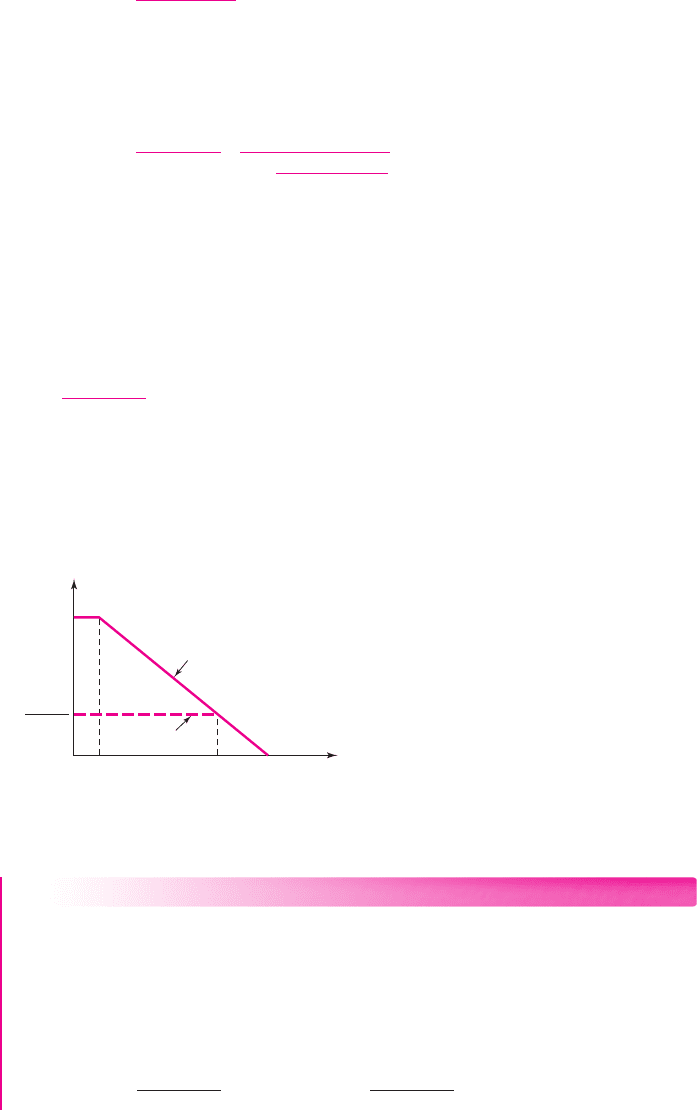
Figure 12.2 Open-loop and closed-loop gain versus frequency, illustrating
bandwidth extension
The closed-loop gain of the feedback amplifier can be expressed as
A
f
(s) =
A(s)
(1 + β A(s))
(12.14)
where we assume that the feedback transfer function
β
is independent of frequency.
Substituting Equation (12.13) into Equation (12.14), we can write the closed-loop
gain in the form
A
f
(s) =
A
o
(1 + β A
o
)
·
1
1 +
s
ω
H
(1 + β A
o
)
(12.15)
From Equation (12.15), we see that the low-frequency closed-loop gain is smaller
than the open-loop gain by a factor of (
1 + β A
o
), but the closed-loop 3 dB frequency
is larger than the open-loop value by a factor of (
1 + β A
o
).
If we multiply the low-frequency open-loop gain A
o
by the bandwidth (3 dB fre-
quency)
ω
H
, we obtain
A
o
ω
H
, which is the gain–bandwidth product. The product of
the low-frequency closed-loop gain and the closed-loop band-width is
A
o
(1 + β A
o
)
[ω
H
(1 + β A
o
)] = A
o
ω
H
(12.16)
Equation (12.16) states that the gain-bandwidth product of a feedback amplifier
is a constant. That is, for a given circuit, we can increase the gain at the expense of a
reduced bandwidth, or we can increase the bandwidth at the expense of a reduced
gain. This property is illustrated in Figure 12.2.
858 Part 2 Analog Electronics
EXAMPLE 12.3
Objective: Determine the bandwidth of a feedback amplifier.
Consider a feedback amplifier with an open-loop low-frequency gain of
A
o
= 10
4
, an open-loop bandwidth of
ω
H
= (2π)(100) rad/s
, and a closed-loop
low-frequency gain of
A
f
(0) = 50
.
Solution: From Equation (12.15), the low-frequency closed-loop gain is
A
f
(0) =
A
o
(1 + β A
o
)
or
50 =
10
4
(1 + β A
o
)
nea80644_ch12_851-946.qxd 6/23/09 1:45 PM Page 858 pmath DATA-DISK:Desktop Folder:23/06/09:MHDQ134-12:

which yields
(1 + β A
o
) =
10
4
50
= 200
From Equation (12.15), the closed-loop bandwidth is
ω
fH
= ω
H
(1 + β A
o
) = (2π)(100)(200) = (2π)(20 × 10
3
)
Comment: The bandwidth increases from 100 Hz to 20 kHz as the gain decreases
from 10
4
to 50.
EXERCISE PROBLEM
Ex 12.3: (a) A feedback amplifier has an open-loop low-frequency gain of
A
O
= 5 ×10
4
, an open-loop bandwidth of
ω
H
=
(
2π
)(
5
)
rad/s, and a closed-
loop low-frequency gain of
A
f
(
0
)
= 80
. Determine (i)
β
and (ii) the closed-loop
bandwidth. (b) Using the results of part (a), if
β
is reduced by 50 percent,
determine the percent change in (i)
A
f
(
0
)
and (ii)
ω
fH
? (Ans. (a) (i)
β = 0.01248
,
(ii)
ω
fH
= (2π)(3.125 ×10
3
)
rad/s; (b) (i)
+100%
, (ii)
−50%)
Noise Sensitivity
In any electronic system, unwanted random and extraneous signals may be present in
addition to the desired signal. These random signals are called noise. Electronic
noise can be generated within an amplifier, or may enter the amplifier along with the
input signal. Negative feedback may reduce the noise level in amplifiers; more accu-
rately, it may increase the signal-to-noise ratio. More precisely, feedback can help
reduce the effect of noise generated in an amplifier, but it cannot reduce the effect
when the noise is part of the input signal.
The input signal-to-noise ratio is defined as
(SNR)
i
=
S
i
N
i
=
v
i
v
n
(12.17)
where
S
i
= v
i
is the input source signal and
N
i
= v
n
is the input noise signal. The
output signal-to-noise ratio is
(SNR)
o
=
S
o
N
o
=
A
Ti
S
i
A
Tn
N
i
(12.18)
where the desired output signal is
S
o
= A
Ti
S
i
and the output noise signal is
N
o
=
A
Tn
N
i
. The parameter A
Ti
is the amplification factor that multiplies the source signal,
and the parameter A
Tn
is the amplification factor that multiplies the noise signal. A
large signal-to-noise ratio allows the signal to be detected without any loss of infor-
mation. This is a desirable characteristic.
The following example compares the signal and noise amplification factors,
which may or may not be equal.
12.2.4
Chapter 12 Feedback and Stability 859
nea80644_ch12_851-946.qxd 6/23/09 1:45 PM Page 859 pmath DATA-DISK:Desktop Folder:23/06/09:MHDQ134-12:
(a) (b)
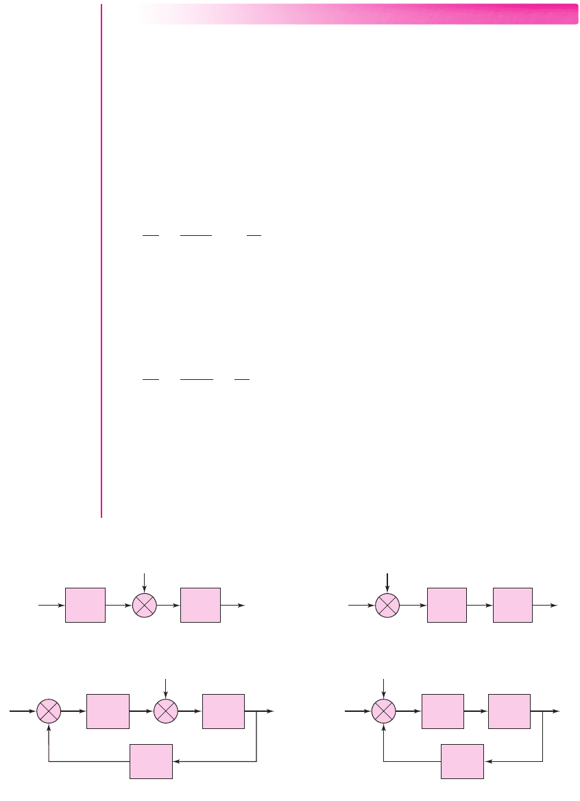
(c) (d)
v
i
v
n
v
oA
A
1
= 10
+
+
A
2
= 10
v
oB
v
n
+
+
A
1
= 10 A
2
= 10
v
i
v
oC
A
1
= 10
3
v
fb
+
+
+
–
v
e
b = 0.01
A
2
= 10
v
i
v
n
+
–
+
v
i
A
2
= 10
A
1
= 10
3
b = 0.01
v
fb
v
oD
v
e
v
n
Figure 12.3 Four amplifier configurations with different input noise sources
EXAMPLE 12.4
Objective: Determine the effect of feedback on the source signal and noise signal
levels.
Consider the four possible amplifier configurations shown in Figure 12.3. The
amplifiers are designed to provide the same output signal voltage. Determine the
effect of the noise signal
v
n
.
Solution (Figure 12.3(a)): Two open-loop amplifiers are in a cascade configuration,
and the noise signal is generated between the two amplifiers. The output voltage is
v
oa
= A
1
A
2
v
i
+ A
2
v
n
= 100v
i
+10v
n
Therefore, the output signal-to-noise ratio is
S
o
N
o
=
100v
i
10v
n
= 10
S
i
N
i
Solution (Figure 12.3(b)): Two open-loop amplifiers are in a cascade configuration,
and the noise is part of the input signal. The output voltage is
v
ob
= A
1
A
2
v
i
+ A
1
A
2
v
n
= 100v
i
+100v
n
Therefore, the output signal-to-noise ratio is
S
o
N
o
=
100v
i
100v
n
=
S
i
N
i
Solution (Figure 12.3(c)): Two amplifiers are in a feedback configuration, and the
noise signal is generated between the two amplifiers. The output voltage is
v
oc
= A
1
A
2
v
ε
+ A
2
v
n
and the feedback signal is
v
fb
= βv
oc
860 Part 2 Analog Electronics
nea80644_ch12_851-946.qxd 6/24/09 10:32 AM Page 860 pmath DATA-DISK:Desktop Folder:24/06/09:MHDQ134-12:

Then,
v
ε
= v
i
−v
fb
= v
i
−βv
oc
therefore,
v
oc
= A
1
A
2
(v
i
−βv
oc
) + A
2
v
n
or
v
oc
=
A
1
A
2
(1 + β A
1
A
2
)
· v
i
+
A
2
(1 + β A
1
A
2
)
· v
n
∼
=
100v
i
+0.1v
n
The output signal-to-noise ratio is
S
o
N
o
=
100v
i
0.1v
n
= 1000
S
i
N
i
Solution (Figure 12.3(d)): A basic feedback configuration, and the noise is part of
the input signal. The output voltage is
v
od
=
A
1
A
2
(1 + β A
1
A
2
)
(v
i
+v
n
)
∼
=
100v
i
+100v
n
Therefore, the output signal-to-noise ratio is
S
o
N
o
=
100v
i
100v
n
=
S
i
N
i
Comment: Comparing the four configurations, we see that Figure 12.3(c) produces
the largest output signal-to-noise ratio. This configuration may occur when amplifier
A
2
is an audio power-amplifier stage, in which large currents can produce excessive
noise, and when amplifier A
1
corresponds to a low-noise preamplifier, which provides
most of the voltage gain.
EXERCISE PROBLEM
Ex 12.4: (a) Consider the circuit shown in Figure 12.3(a). Assume
A
1
= 100
and
A
2
= 10
. Determine the output signal-to-noise ratio in terms of the input
signal-to-noise ratio. (b) Consider the circuit shown in Figure 12.3(c). Assume
A
1
= 10
4
,
A
2
= 10
, and
β = 0.001
. Determine the output signal-to-noise ratio
in terms of the input signal-to-noise ratio. (Ans. (a)
S
o
/N
o
= 100(S
i
/N
i
)
,
(b)
S
o
/N
o
= 10
4
(S
i
/N
i
)
)
We must emphasize that the increased signal-to-noise ratio due to feedback occurs
only in specific situations. As indicated in Figure 12.3(d), when noise is effectively
part of the amplifier input signal, the feedback mechanism does not improve the ratio.
Reduction of Nonlinear Distortion
Distortion in an output signal is caused by a change in the basic amplifier gain or a
change in the slope of the basic amplifier transfer function. The change in gain is a
function of the nonlinear properties of bipolar and MOS transistors used in the basic
amplifier.
12.2.5
Chapter 12 Feedback and Stability 861
nea80644_ch12_851-946.qxd 6/23/09 1:45 PM Page 861 pmath DATA-DISK:Desktop Folder:23/06/09:MHDQ134-12:
S
e1
S
e 2
S
e
(error signal)
S
o
S
o2
S
o1
A
1
= 1000
A
3
= 250
A
2
= 500
(a)
(b)
S
i1
S
i
(input signal)
S
o
S
o2
S
o1
S
i2
A
f1
= = 10.0
1000
1 + (0.099)(1000)
A
f 2
= = 9.90
500
1 + (0.099)(500)
A
f 3
= = 9.71
250
1 + (0.099)(250)
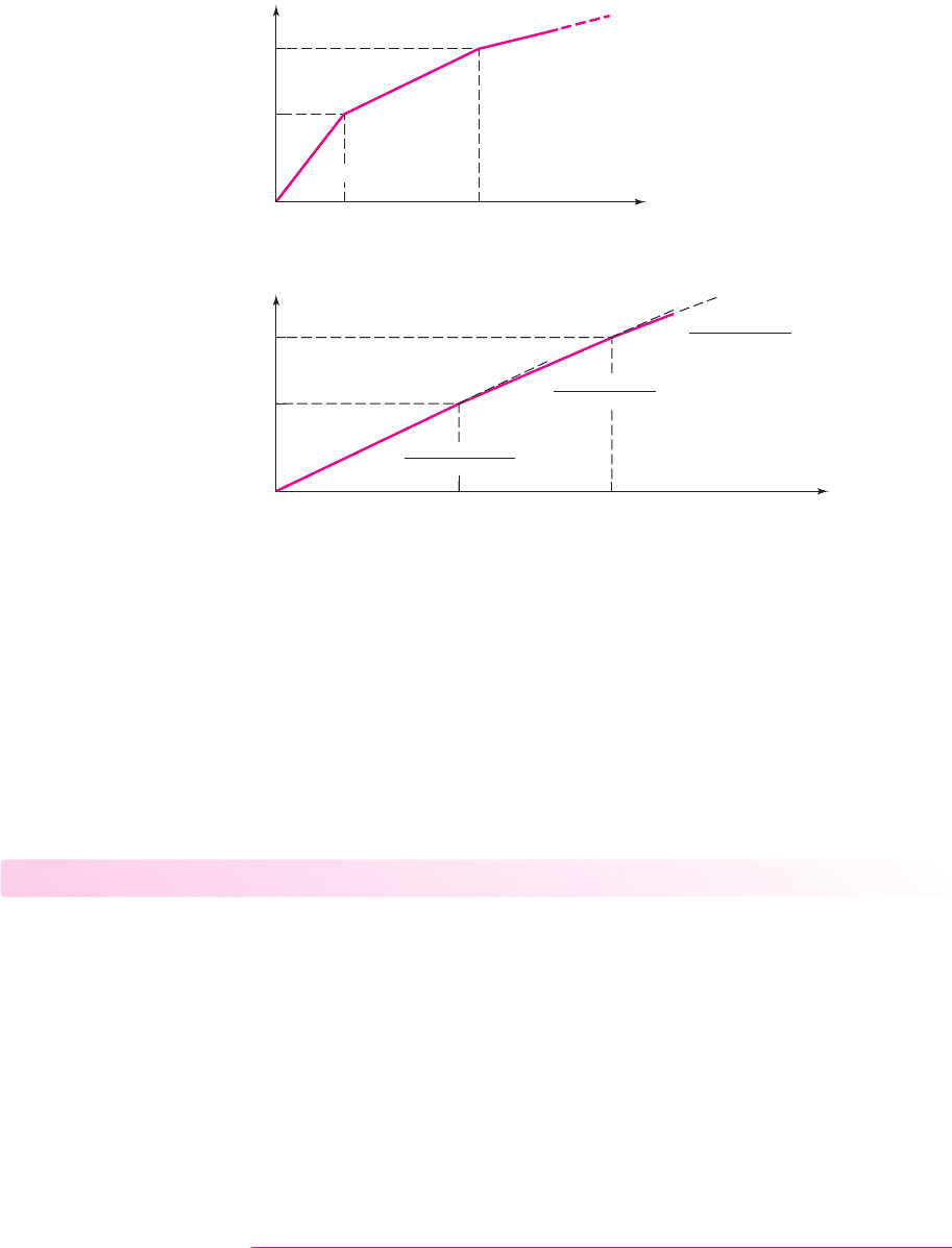
Figure 12.4 (a) Basic amplifier (open-loop) transfer characteristics; (b) closed-loop transfer
characteristics
Assume the basic amplifier, or open-loop, transfer function is as shown in Fig-
ure 12.4(a), which shows changes in gain as the input signal amplitude changes. The
gain values are shown on the figure. When this amplifier is incorporated in a feed-
back circuit with a feedback transfer function of
β = 0.099
, the resulting closed-loop
transfer characteristics are shown in Figure 12.4(b). This transfer function also has
changes in gain but, whereas the open-loop gain changes by a factor of 2, the closed-
loop gain changes by only 1 percent and 2 percent, respectively. A smaller change in
gain means less distortion in the output signal of the negative feedback amplifier.
Test Your Understanding
TYU 12.1 (a) The closed-loop gain of a feedback amplifier is
A
f
= 50
and the
feedback transfer function is
β = 0.019
. Determine the open-loop gain
A
. (b) If the
open-loop gain is
A = 5 ×10
5
and
β = 0.019
, find the closed-loop gain
A
f
. (Ans.
(a)
A = 10
3
, (b)
A
f
= 52.63)
TYU 12.2 The gain factors in a feedback system are
A = 5 ×10
5
and
A
f
= 100
.
Parameter A
f
must not change more than
±0.001
percent because of a change in A.
What is the maximum allowable variation in A? (Ans.
±5%
)
TYU 12.3 In a feedback system, the basic amplifier open-loop low-frequency gain is
A
o
= 5 ×10
5
and the open-loop 3 dB frequency is 6 Hz. (a) If the required closed-loop
bandwidth is
f = 200
kHz, determine the maximum closed-loop low-frequency gain
A
f
(
0
)
. (b) If the required closed-loop bandwidth is
f = 100
kHz, what is the maxi-
mum closed-loop low-frequency gain
A
f
(0)
? (Ans. (a)
A
f
(0) = 15
, (b)
A
f
(0) = 30)
862 Part 2 Analog Electronics
nea80644_ch12_851-946.qxd 6/23/09 1:45 PM Page 862 pmath DATA-DISK:Desktop Folder:23/06/09:MHDQ134-12:
A
v
b
v
R
S
R
L
V
i
+
–
(a) Series–shunt
(b) Shunt–series
(d) Shunt–shunt
(c) Series–series
A
g
b
z
R
S
R
L
V
i
+
–
I
o
A
i
b
i
I
i
R
S
R
L
I
o
A
z
b
g
R
S
R
L
I
i
+
–
V
o
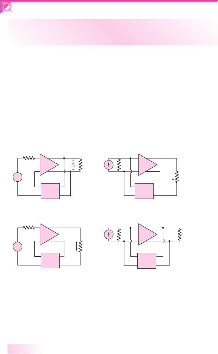
Figure 12.5 Basic feedback connections
12.3 IDEAL FEEDBACK TOPOLOGIES
Objective: • Analyze the four ideal feedback circuit configurations and
determine circuit characteristics including input and output resistances.
There are four basic feedback topologies, based on the parameter to be amplified (volt-
age or current) and the output parameter (voltage or current). The four feedback circuit
categories can be described by the types of connections at the input and output of circuit.
The four types of connections are shown in Figure 12.5. The four connections are
referred to as: series–shunt (voltage amplifier), shunt–series (current amplifier),
series–series (transconductance amplifier), and shunt–shunt (transresistance amplifier).
The first term refers to the connection at the amplifier input, and the second term refers
to the connection at the output. Also, the type of connection determines which parame-
ter (voltage or current) is sampled at the output and which parameter is amplified. The
connections also determine the feedback amplifier characteristics—in particular, the
input and output resistances. The resistance parameters become an important circuit
property, when, for example, we consider voltage amplifiers versus current amplifiers.
Chapter 12 Feedback and Stability 863
In this section, we will determine the ideal transfer functions and the ideal input
and output resistances of each of the four feedback topologies. In later sections, we
will compare actual versus ideal feedback circuit characteristics.
As a note, the ideal topologies are small-signal equivalent circuits; therefore,
phasor notation is used throughout this analysis.
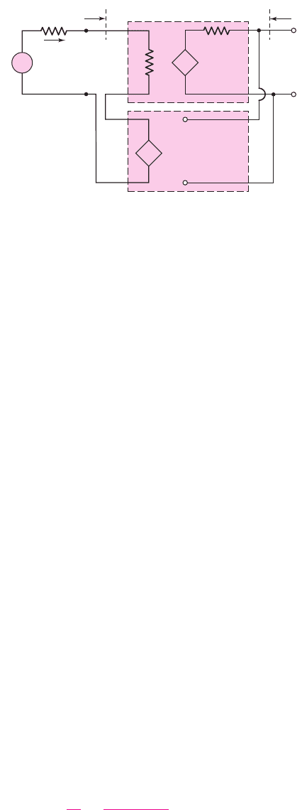
Series–Shunt Configuration
The configuration of an ideal series–shunt feedback amplifier is shown in Fig-
ure 12.6. The circuit consists of a basic voltage amplifier with an input resistance R
i
12.3.1
nea80644_ch12_851-946.qxd 6/23/09 1:45 PM Page 863 pmath DATA-DISK:Desktop Folder:23/06/09:MHDQ134-12:
A
v
V
e
V
i
R
S
R
o
R
i
+
–
V
o
+
–
V
o
+
–
V
fb
+
–
V
e
+
–
+
–
+
–
R
if
R
of
I
i
b
v
V
o
Figure 12.6 Ideal series–shunt feedback topology
and an open-loop voltage gain
A
v
. The feedback circuit samples the output voltage
and produces a feedback voltage
V
fb
, which is in series with the input signal voltage
V
i
. In this ideal configuration, the input resistance to the feedback circuit is infinite;
therefore, there is no loading effect on the output of the basic amplifier due to the
feedback circuit.
Voltage
V
ε
is the difference between the input signal voltage and the feedback
voltage and is called an error signal. The error signal is amplified in the basic voltage
amplifier. We can recognize the series connection on the input and the shunt connec-
tion of the output for this configuration.
The feedback circuit is a voltage-controlled voltage source and is an ideal volt-
age amplifier. The feedback circuit samples the output voltage and provides a feed-
back voltage in series with the source voltage. For example, an increase in the output
voltage produces an increase in the feedback voltage, which in turn decreases the
error voltage due to the negative feedback. Then, the smaller error voltage is ampli-
fied producing a smaller output voltage, which means that the output signal tends to
be stabilized.
If the output of the feedback network is an open circuit, then the output volt-
age is
V
o
= A
v
V
ε
(12.19)
and the feedback voltage is
V
fb
= β V
o
= β
v
V
o
(12.20)
Parameter
β
v
is the voltage feedback transfer function, which is the ratio of the feed-
back voltage to the output voltage. The notation is similar to the voltage gain
A
v
,
which is also the ratio of two voltages.
The error voltage, assuming the source resistance R
S
is negligible, is
V
ε
= V
i
− V
fb
(12.21)
Combining Equations (12.19), (12.20), and (12.21), we find the closed-loop voltage
transfer function is
A
v f
=
V
o
V
i
=
A
v
(1 + β
v
A
v
)
(12.22)
Equation (12.22) is the closed-loop voltage gain of the feedback amplifier, and it has
the same form as the ideal feedback transfer function given by Equation (12.5).
864 Part 2 Analog Electronics
nea80644_ch12_851-946.qxd 6/23/09 1:45 PM Page 864 pmath DATA-DISK:Desktop Folder:23/06/09:MHDQ134-12:
V
x
R
o
R
i
+
–
V
fb
+
–
V
e
R
of
=
V
x
I
x
+
–
+
–
+
–
b
v
V
o
= b
v
V
x
A
v
V
e
I
x
Figure 12.7 Ideal series–shunt feedback configuration for determining output resistance
The input resistance including feedback is denoted by
R
if
. Starting with Equa-
tion (12.21), using Equations (12.19) and (12.20), we find that
V
i
= V
ε
+ V
fb
= V
ε
+β
v
V
o
= V
ε
+β
v
(A
v
V
ε
)
(12.23(a))
or
V
ε
=
V
i
(1 + β
v
A
v
)
(12.23(b))
The input current is
I
i
=
V
ε
R
i
=
V
i
R
i
(1 + β
v
A
v
)
(12.24)
and the input resistance with feedback is then
R
if
=
V
i
I
i
= R
i
(1 + β
v
A
v
)
(12.25)
Equation (12.25) shows that a series input connection results in an increased
input resistance compared to that of the basic voltage amplifier. A large input resis-
tance is a desirable property of a voltage amplifier. This eliminates loading effects on
the input signal source.
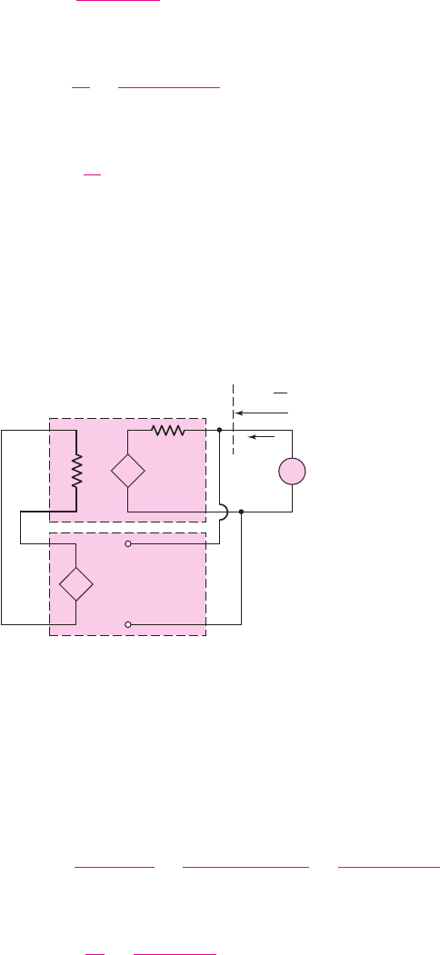
The output resistance of the feedback circuit can be determined from the equiv-
alent circuit in Figure 12.7. The input signal voltage source is set equal to zero
(a short circuit), and a test voltage is applied to the output terminals.
Chapter 12 Feedback and Stability 865
From the circuit, we see that
V
ε
+ V
fb
= V
ε
+β
v
V
x
= 0
(12.26(a))
or
V
ε
=−β
v
V
x
(12.26(b))
The output current is
I
x
=
V
x
− A
v
V
ε
R
o
=
V
x
− A
v
(−β
v
V
x
)
R
o
=
V
x
(1 + β
v
A
v
)
R
o
(12.27)
and the output resistance, including feedback, is
R
of
=
V
x
I
x
=
R
o
(1 + β
v
A
v
)
(12.28)
nea80644_ch12_851-946.qxd 6/23/09 1:45 PM Page 865 pmath DATA-DISK:Desktop Folder:23/06/09:MHDQ134-12:
A
vf
V
i
′
V
i
R
of
R
if
+
–
V
i
′
V
o
+
–
R
L
R
S
+
–
+
–
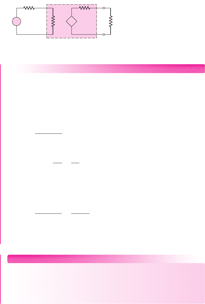
Figure 12.8 Equivalent circuit of the series–shunt feedback circuit or voltage amplifier
Equation (12.28) shows that a shunt output connection results in a decreased
output resistance compared to that of the basic voltage amplifier. A small output
resistance is a desirable property of a voltage amplifier. This eliminates loading ef-
fects on the output signal when an output load is connected.
The equivalent circuit of this feedback voltage amplifier is shown in Figure 12.8.
866 Part 2 Analog Electronics
EXAMPLE 12.5
Objective: Determine the input resistance of a series input connection and the out-
put resistance of a shunt output connection for an ideal feedback voltage amplifier.
Consider a series–shunt feedback amplifier in which the open-loop gain is
A
v
= 10
5
and the closed-loop gain is
A
v f
= 50
. Assume the input and output resis-
tances of the basic amplifier are
R
i
= 10 k
and
R
o
= 20 k
, respectively.
Solution: The ideal closed-loop voltage transfer function is, from Equation (12.22),
A
v f
=
A
v
(1 + β
v
A
v
)
or
(1 + β
v
A
v
) =
A
v
A
v f
=
10
5
50
= 2 ×10
3
From Equation (12.25), the input resistance is
R
if
= R
i
(1 + β
v
A
v
) = (10)(2 ×10
3
) k ⇒ 20 M
and, from Equation (12.28), the output resistance is
R
of
=
R
o
(1 + β
v
A
v
)
=
20
2 × 10
3
k ⇒ 10
Comment: With a series input connection, the input resistance increases drastically,
and with a shunt output connection, the output resistance decreases substantially,
with negative feedback. These are the desired characteristics of a voltage amplifier.
EXERCISE PROBLEM
Ex 12.5: An ideal series–shunt feedback amplifier is shown in Figure 12.6.
Assume R
S
is negligibly small. (a) If
V
i
= 100
mV,
V
fb
= 99
mV, and
V
o
= 5
V,
determine
A
v
,
β
v
, and
A
v f
, including units. (b) Using the results of part (a),
determine
R
if
and
R
of
, for
R
i
= 5k
and
R
o
= 4k
. (Ans. (a)
A
v
= 5000
V/V,
β
v
= 0.0198
V/V,
A
v f
= 50
V/V (b)
R
if
= 500 k
,
R
of
= 40
)
nea80644_ch12_851-946.qxd 6/23/09 1:45 PM Page 866 pmath DATA-DISK:Desktop Folder:23/06/09:MHDQ134-12:
I
i
R
S
I
o
R
i
+
–
V
i
R
o
b
i
I
o
A
i
I
e
R
of
R
if
I
e
I
fb
Figure 12.9 Ideal shunt–series feedback topology
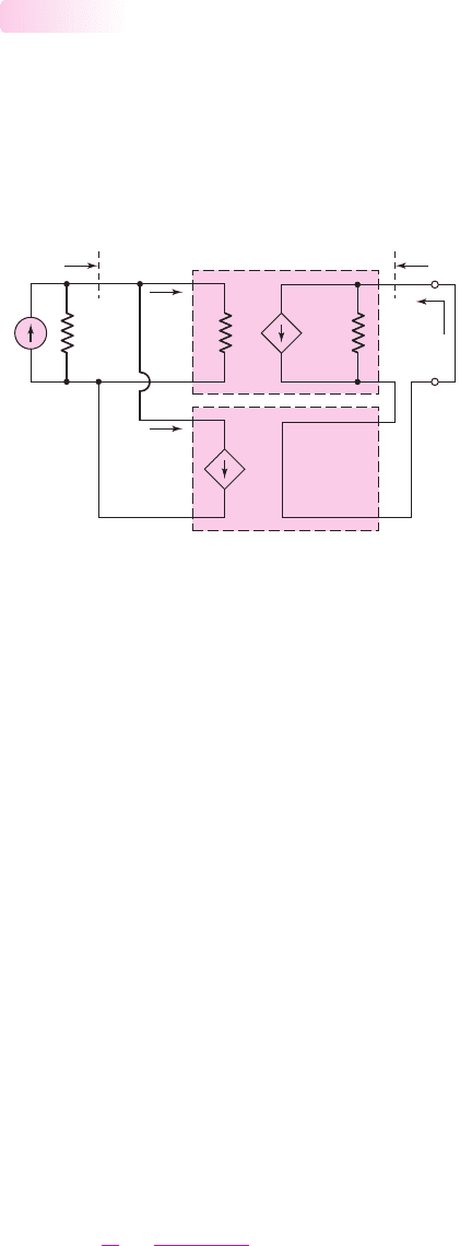
Shunt–Series Configuration
The configuration of an ideal shunt–series feedback amplifier is shown in Fig-
ure 12.9. The circuit consists of a basic current amplifier with an input resistance R
i
and an open-loop current gain A
i
. The feedback circuit samples the output current
and produces a feedback current
I
fb
, which is in shunt with an input signal current I
i
.
In this ideal configuration, the feedback circuit does not load down the basic ampli-
fier output; therefore, the load current I
o
is not affected.
12.3.2
Chapter 12 Feedback and Stability 867
Current
I
ε
is the difference between the input signal current and the feedback
current and is the error signal. The error signal is amplified in the basic current
amplifier. We can recognize the shunt connection on the input and the series connec-
tion on the output for this configuration.
This circuit is a current-controlled current source and is an ideal current amplifier.
The feedback circuit samples the output current and provides a feedback signal in shunt
with the signal current. An increase in output current produces an increase in feedback
current, which in turn decreases the error current. The smaller error current is then
amplified, producing a smaller output current and stabilizing the output signal.
The input source shown is a Norton equivalent circuit; it could be converted to a
Thevenin equivalent circuit.
If the output is essentially a short circuit, then the output current is
I
o
= A
i
I
ε
(12.29)
and the feedback current is
I
fb
= β I
o
= β
i
I
o
(12.30)
The parameter
β
i
is the feedback current transfer function. The input signal current,
assuming R
S
is large, is
I
i
= I
ε
+ I
fb
(12.31)
Combining Equations (12.29), (12.30), and (12.31) yields the closed-loop current
transfer function
A
if
=
I
o
I
i
=
A
i
(1 + β
i
A
i
)
(12.32)
Equation (12.32) is the closed-loop current gain of the feedback amplifier.
nea80644_ch12_851-946.qxd 6/23/09 1:45 PM Page 867 pmath DATA-DISK:Desktop Folder:23/06/09:MHDQ134-12: