Neamen D. Microelectronics: Circuit Analysis and Design
Подождите немного. Документ загружается.

+
~
–
4
2
3
0
0
0
0
5
7
1
6
+
–
5 V
+
–
5 V
10 mV
+
–
v
4
v
3
v+
v–
v
1
5 kΩ
R
S
49 kΩ
1 kΩ
R
2
R
1
0
V
75 Ω
R
L
o
S2
o
S1
U
1
mA – 741
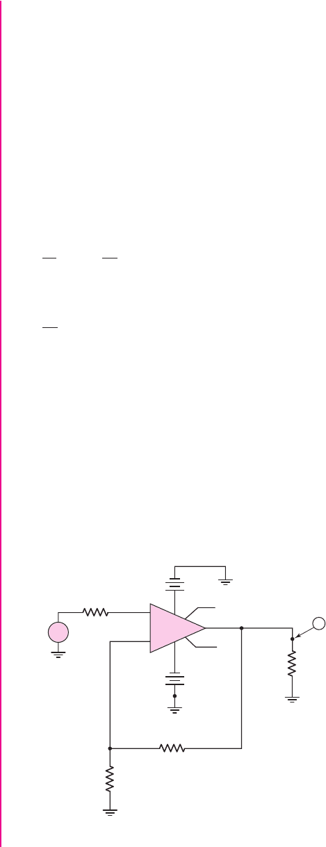
Figure 12.19 Circuit used in the computer simulation analysis in Example 12.8
The closed-loop voltage gain must be
A
v f
= 0.5/0.01 = 50
. For the ideal case,
A
v f
= 1/β
v
, so the feedback transfer function is
β
v
= 1/50 = 0.02
. The loop gain is
then
T = β
v
A
v
= (0.02)(10
4
) = 200
Referring to Table 12.1, we expect the input resistance to be
R
if
∼
=
(10)(200) k → 2M
and the output resistance to be
R
of
∼
=
(100/200)= 0.5
These input and output resistance values will minimize any loading effects at the
amplifier input and output terminals.
If we use the noninverting amplifier configuration in Figure 12.16, then we have
1
β
v
= 1 +
R
2
R
1
= 50
and
R
2
R
1
= 49
The feedback network loads the output of the amplifier; consequently, we need
R
1
+ R
2
to be much larger than R
o
. However, the output resistance of the feedback
network is in series with the input terminals, so extremely large values of R
1
and R
2
will reduce the actual signal applied to the op-amp because of voltage divider action.
Initially, then, we choose
R
1
= 1k
and
R
2
= 49 k
.
Computer Simulation Verification: The circuit in Figure 12.19 was used in a PSpice
analysis of the voltage amplifier. A standard 741 op-amp was used in the circuit. For a
10 mV input signal, the output signal was 499.6 mV, for a gain of 49.96. This result is
within 0.08 percent of the ideal designed value. The input resistance
R
if
was found to
be approximately
580 M
and the output resistance
R
of
was determined to be
approximately
0.042
. The differences between the measured input and output
878 Part 2 Analog Electronics
nea80644_ch12_851-946.qxd 6/23/09 1:45 PM Page 878 pmath DATA-DISK:Desktop Folder:23/06/09:MHDQ134-12:

resistances compared to the predicted values are due to the differences between the
actual
μA
-741 op-amp parameters and the assumed parameters. However, the mea-
sured input resistance is larger than predicted and the measured output resistance is
smaller than predicted, which is desired and more in line with an ideal op-amp circuit.
Comment: An almost ideal feedback voltage amplifier can be realized if an op-amp
is used in the circuit.
EXERCISE PROBLEM
*Ex 12.8: Design a feedback voltage amplifier to provide a voltage gain of 15.
The nominal voltage source resistance is
R
S
= 2k
, and the nominal load is
R
L
= 100
. An op-amp with parameters
R
i
= 5k
,
R
o
= 50
, and a low-
frequency open-loop gain of
A
v
= 5 ×10
3
is available. Correlate the design with
a computer simulation analysis to determine the voltage gain, input resistance,
and output resistance.
Test Your Understanding
TYU 12.6 Assume the transistor in the emitter-follower circuit in Figure 12.18(a) is
biased such that
I
CQ
= 1.2
mA. Let
R
E
= 1.5
k
. (a) If the transistor current gain is
h
FE
= 120
, determine
A
v f
,
R
if
, and
R
of
. (b) Determine the percent change in
A
v f
,
R
if
, and
R
of
if the transistor current gain increases to
h
FE
= 180
. Assume
the quiescent collector current remains unchanged. (Ans. (a)
A
v f
= 0.985877
,
R
if
=
184.1
k
,
R
of
= 21.18
; (b)
A
v f
:
−0.00386
%,
R
if
:
+49.6%
,
R
of
:
+0.283%)
TYU 12.7 (a) Assume the transistor in the source-follower circuit shown in Figure
12.18(b) is biased at
I
DQ
= 250 μ
A. Let
R
S
= 3
k
. If the transistor parameters are
K
n
= 0.5
mA/V
2
,
V
TN
= 0.8
V, and
λ = 0
, determine
A
v f
and
R
of
. (b) Determine the
percent change in
A
v f
and
R
of
if the quiescent drain current is increased to
I
DQ
=
1
mA. (Ans. (a)
A
v f
= 0.6796
,
R
of
= 961
; (b)
A
v f
:
+19.1%
,
R
of
:
−40.5%)
12.5 CURRENT (SHUNT–SERIES) AMPLIFIERS
Objective: • Analyze op-amp and discrete transistor circuit examples
of shunt–series (current) feedback amplifiers.
In this section, we will analyze an op-amp and a discrete circuit representation of the
shunt–series feedback amplifier. The shunt–series circuit is a current amplifier; there-
fore, we must derive the output current to input current transfer function. For the
ideal configuration, this function is given in Equation (12.32):
A
if
=
A
i
(1 + β
i
A
i
)
where A
i
is the basic amplifier current gain and
β
i
is the current feedback transfer
function. For this amplifier, the input resistance decreases and the output resistance
increases compared to the basic amplifier values.
Chapter 12 Feedback and Stability 879
nea80644_ch12_851-946.qxd 6/23/09 1:45 PM Page 879 pmath DATA-DISK:Desktop Folder:23/06/09:MHDQ134-12:
V
o
I
i
R
S
I
e
I
i
′
I
fb
I
1
V
1
R
1
I
o
R
F
R
L
R
if
–
+
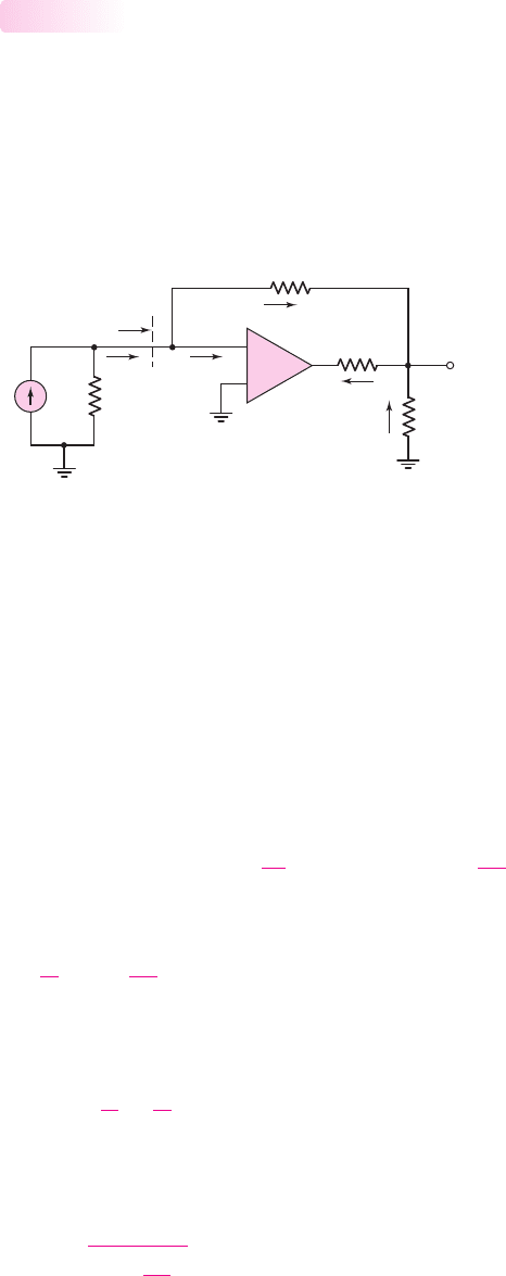
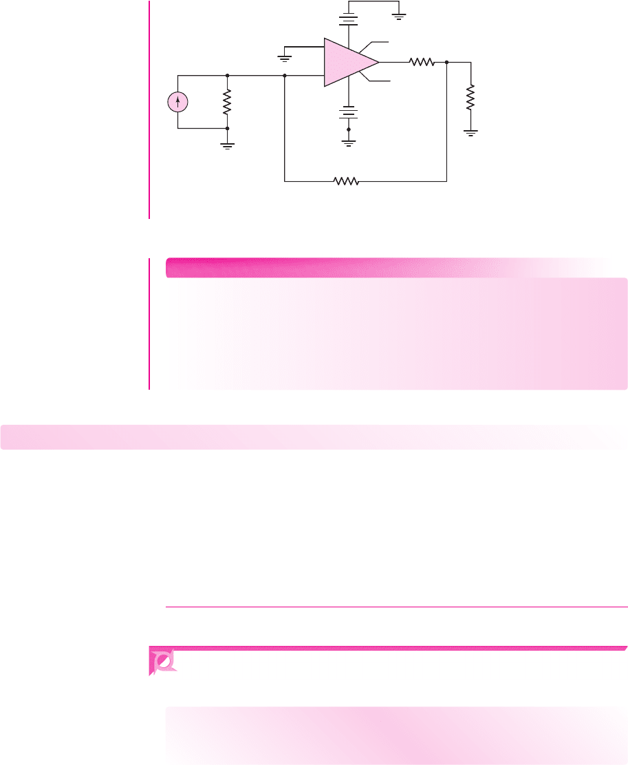
Figure 12.20 Example of an op-amp shunt–series feedback circuit
Op-Amp Circuit Representation
Figure 12.20 shows an op-amp current amplifier, which is a shunt–series configura-
tion. The input signal is the current
I
i
from the Norton equivalent source of I
i
and R
S
.
The feedback current is
I
fb
, the error signal is the current
I
ε
, and the output signal
is the current I
o
. With the shunt input connection, the input resistance
R
if
is small, as
previously stated. Resistance R
S
is the output resistance of the current source and is
normally large. If
R
S
R
if
, then
I
i
∼
=
I
i
.
12.5.1
If we assume initially that
I
ε
is negligible, then, from Figure 12.20, we have
I
i
∼
=
I
i
= I
fb
The output voltage V
o
, assuming V
1
is at virtual ground, is
V
o
=−I
fb
R
F
=−I
i
R
F
and current I
1
is
I
1
=−V
o
/R
1
The output current can be expressed
I
o
= I
fb
+ I
1
= I
i
+
−
1
R
1
(−I
i
R
F
) = I
i
1 +
R
F
R
1
(12.57)
Therefore, the ideal current gain is
I
o
I
i
= 1 +
R
F
R
1
(12.58)
In the ideal feedback circuit, the amplification factor A
i
is very large; conse-
quently, the current transfer function, from Equation (12.32), becomes
A
if
=
I
o
I
i
∼
=
1
β
i
(12.59)
Comparing Equation (12.59) with (12.58), we see that the current feedback transfer
function for the ideal op-amp current amplifier is
β
i
=
1
1 +
R
F
R
1
(12.60)
880 Part 2 Analog Electronics
nea80644_ch12_851-946.qxd 6/23/09 1:45 PM Page 880 pmath DATA-DISK:Desktop Folder:23/06/09:MHDQ134-12:
A
i
I
e
V
1
R
L
–
+
R
i
R
F
R
1
I
i
R
S
I
e
I
i
′
I
fb
I
1
I
o
V
o
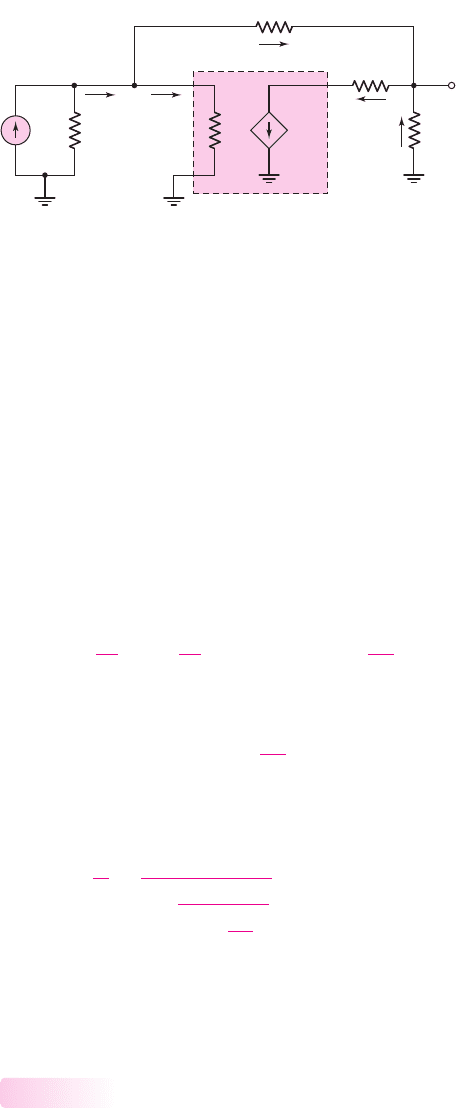
Figure 12.21 Equivalent circuit, op-amp shunt–series feedback configuration
We can take the finite amplifier gain into account by considering the equivalent
circuit in Figure 12.21. The parameter A
i
is the open-loop current gain. We have
I
o
= A
i
I
ε
(12.61)
and
I
ε
= I
i
− I
fb
∼
=
I
i
− I
fb
(12.62)
therefore,
I
o
= A
i
(I
i
− I
fb
)
(12.63)
If we again assume that V
1
is at virtual ground, voltage V
o
is given by
V
o
=−I
fb
R
F
(12.64)
We can then write
I
1
=−
V
o
R
1
=−
1
R
1
(−I
fb
R
F
) = I
fb
R
F
R
1
(12.65)
The output current is also expressed as
I
o
= I
fb
+ I
1
= I
fb
+ I
fb
R
F
R
1
(12.66)
Solving for
I
fb
from Equation (12.66), substituting that into Equation (12.63), and
rearranging terms yields the closed-loop current gain
A
if
=
I
o
I
i
=
A
i
1 +
A
i
1 +
R
F
R
1
(12.67)
Since the current feedback transfer function is
β
i
= 1/[1 +(R
F
/R
1
)]
, the
closed-loop current gain expression for the op-amp current amplifier has the same
form as that for the ideal shunt–series configuration.
Simple Discrete Circuit Representation
Figure l2.22(a) shows the ac equivalent circuit of a common-base circuit, which is an ex-
ample of a simple discrete shunt–series configuration. Figure l2.22(b) is the same circuit
rearranged to demonstrate more clearly the input, feedback, and error components of
12.5.2
Chapter 12 Feedback and Stability 881
nea80644_ch12_851-946.qxd 6/23/09 1:45 PM Page 881 pmath DATA-DISK:Desktop Folder:23/06/09:MHDQ134-12:
(a) (b)
R
L
I
o
I
i
I
e
I
i
I
o
I
fb
I
e
R
L
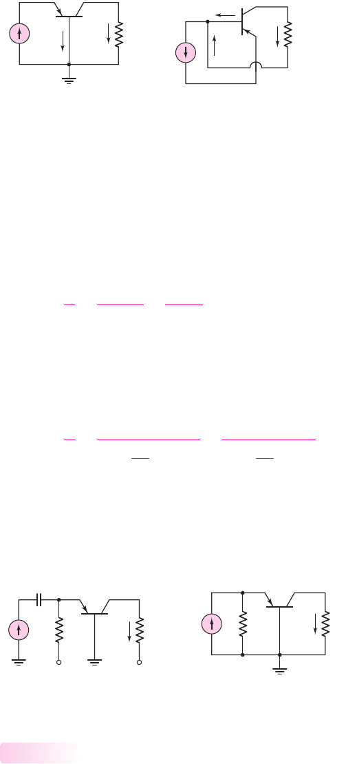
Figure 12.22 (a) Equivalent circuit for simple common-base circuit and
(b) reconfigured circuit
I
o
I
i
R
E
R
C
R
C
i
o
i
i
R
E
V
+
V
–
(a) (b)
Figure 12.23 (a) Common-base circuit, including biasing and (b) ac equivalent circuit
the currents. The output current is equal to the feedback current, which means that the
feedback transfer function is
β
i
= 1
. The basic amplifier gain is
I
o
/I
ε
= A
i
= h
FE
which is simply the common-emitter current gain of the transistor.
From Figure l2.22(b), we see that the closed-loop current transfer function or
gain is
A
if
=
I
o
I
i
=
h
FE
1 + h
FE
=
A
i
1 + A
i
(12.68)
Since the current feedback transfer function
β
i
is unity, Equation (12.68) has the
same form as that for the ideal shunt–series transfer function.
Figure l2.23(a) is a more realistic common-base circuit. Resistor R
E
and the
supply voltages
V
+
and
V
−
bias the transistor in the forward-active mode. The ac
equivalent circuit is in Figure l2.23(b). We can show that the current gain is
A
if
=
I
o
I
i
=
h
FE
1 +
r
π
R
E
+ h
FE
=
A
i
1 +
r
π
R
E
+ A
i
(12.69)
Equation (12.69) does not have the same form as the ideal shunt–series feedback
transfer function. This is common in many discrete transistor feedback circuits. The
reason is that resistor R
E
introduces loading effects that are not present in the ideal
configuration. Typically, then, the transfer functions of actual discrete circuits are not
the same as for the ideal case.
882 Part 2 Analog Electronics
Discrete Circuit Representation
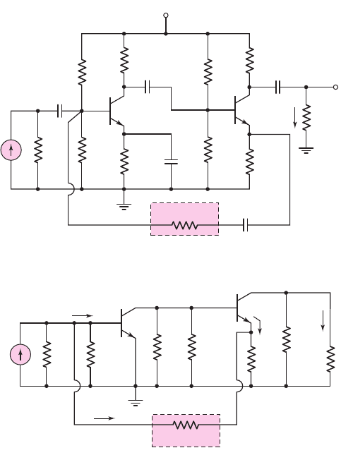
Figure 12.24(a) shows a two-stage discrete transistor circuit example of a shunt–
series feedback configuration. While the large number of capacitors makes this cir-
cuit somewhat impractical, it can be used to illustrate the basic concepts of feedback.
12.5.3
nea80644_ch12_851-946.qxd 6/23/09 1:45 PM Page 882 pmath DATA-DISK:Desktop Folder:23/06/09:MHDQ134-12:
(a)
(b)
R
S
R
F
I
i
R
B2
=
R
3
⎪⎪R
4
R
B1
=
R
1
⎪⎪R
2
R
C1
R
E2
R
L
R
C2
I
o
I
e
I
fb
Q
2
Q
1
I
e
i
i
v
o
R
S
C
E1
C
C1
C
F
C
C3
C
C2
V
CC
= 10 V
R
F
= 10 kΩ
R
2
=
20 kΩ
R
E1
=
1 kΩ
R
C1
=
2 kΩ
R
L
=
4 kΩ
R
E2
=
0.5 kΩ
R
C2
=
4 kΩ
R
1
=
80 kΩ
R
4
=
15 kΩ
R
3
=
85 kΩ
Q
2
Q
1
i
o
Figure 12.24 (a) Example of a discrete transistor shunt–series feedback circuit and
(b) ac equivalent circuit
Figure 12.24(b) shows the ac equivalent circuit, in which all capacitors act as short
circuits. With the shunt input connection, the input signal current is essentially I
i
(as-
suming R
S
is large), the feedback current is
I
fb
, and the error signal is
I
ε
. The signal
emitter current I
e
is directly proportional to the load current I
o
, and the feedback
current is directly proportional to I
e
, demonstrating that this series output connection
samples the output current I
o
.
[Note: It may be argued that, even though I
e
is related to the output current I
o
, the
output current is not part of the feedback circuit. In particular, the output resistance
r
o2
of Q
2
is not within the feedback network. For this reason, the output connection
may be thought of as a shunt connection with the output signal being a voltage at the
emitter of Q
2
. However, we are assuming the output signal is a current so we will
treat this circuit as a shunt-series amplifier.]
The small-signal equivalent circuit is shown in Figure 12.25. We assume that the
small-signal output resistance r
o
of each transistor is infinite. We could derive the
expression for the closed-loop current gain by writing and solving a set of simulta-
neous nodal equations. However, as with most discrete transistor feedback circuits,
the transfer function cannot be arranged exactly in the ideal form without several
approximations. For this circuit, then, we rely on a computer analysis to provide the
required results.
Chapter 12 Feedback and Stability 883
nea80644_ch12_851-946.qxd 6/23/09 1:45 PM Page 883 pmath DATA-DISK:Desktop Folder:23/06/09:MHDQ134-12:

+
–
+
–
R
if
R
of
R
S
R
L
R
C
2
R
F
R
E
2
I
o
I
i
R
B1
g
m1
V
p
1
g
m2
V
p
2
R
C1
⎪⎪
R
B2
V
p
1
V
p
2
r
p
1
r
p
2
Figure 12.25 Small-signal equivalent circuit of circuit in Figure 12.24(a)
EXAMPLE 12.9
Objective: Determine the closed-loop current gain and input resistance of a discrete
shunt–series transistor feedback circuit.
Consider the circuit in Figure 12.24(a), with transistor parameters
h
FE
= 100
and
V
A
=∞
. Assume the source resistance is
R
S
= 10 M
. The capacitors are large
enough to act as short circuits to the signal currents.
Solution: A PSpice analysis shows that the closed-loop current gain is
A
if
= I
o
/I
i
= 9.58
The input resistance
R
if
is defined as the ratio of the signal voltage at the base of Q
1
to the input signal current. The PSpice results show that
R
if
= 134
. This low input
resistance is expected for the shunt input connection.
Comment: The PSpice analysis shows that the closed-loop current gain increases
from 9.58 to 10.2 as the transistor current gain h
FE
increases from 100 to 1000. This
result again demonstrates a principal characteristic of feedback circuits, which is that
the transfer function is relatively insensitive to changes in the individual transistor
parameters.
EXERCISE PROBLEM
*Ex 12.9: Consider the common-base circuit in Figure 12.23(a), with transistor
parameters
h
FE
= 80
,
V
EB
(on) = 0.7
V, and
V
A
=∞
. Assume the transistor is
biased at
I
CQ
= 0.5
mA. Redesign the circuit such that the closed-loop current
gain is greater than 0.95. (Ans.
R
E
(min) = 1.30 k
, and
V
+
(min) = 1.36
V)
From the small-signal equivalent circuit in Figure 12.25, we find that the output
resistance
R
of
looking into the collector of Q
2
is very large. If r
o
of Q
2
is assumed to
be infinite, then
R
of
is also infinite. We expect a large output impedance for the se-
ries output connection of this feedback circuit.
DESIGN EXAMPLE 12.10
Objective: Design a feedback amplifier to provide a given current gain.
Specifications: Assume that a signal current source has a nominal output resistance
of
R
S
= 10 k
and that the amplifier will drive a nominal load of
R
L
= 50
. A cur-
rent gain of 10 is required.
884 Part 2 Analog Electronics
nea80644_ch12_851-946.qxd 6/23/09 1:45 PM Page 884 pmath DATA-DISK:Desktop Folder:23/06/09:MHDQ134-12:

Choices: An op-amp with the same characteristics described in Example 12.8 is
available.
Solution (Design Approach): An amplifier with a low input resistance and a large
output resistance is required, to minimize loading effects at the input and output. For
these reasons, a shunt–series feedback configuration, or current amplifier, will be
used.
The closed-loop gain is
A
if
= 10
∼
=
1/β
i
and the feedback transfer function is
β
i
= 0.1.
The dependent open-loop voltage source of the op-amp, as shown in Figure 12.17,
can be transformed to an equivalent dependent open-loop current source, as shown in
Figure 12.9. We find that
A
i
= A
v
R
i
/R
o
Using the parameters specified for the op-amp, we find
A
i
= 10
6
. The loop gain for
the shunt–series configuration is
A
i
β
i
= (10
6
)
(
0.1
)
= 10
5
Referring to Table 12.1, we expect the input resistance to be
R
if
= 10/10
5
k → 0.1
and the output resistance to be
R
of
= (100)(10
5
)→ 10 M
These resistance values will minimize any loading effects at the amplifier input and
output.
For the shunt–series configuration in Figure 12.20, we have
1
β
i
= 1 +
R
F
R
1
= 10
or
R
F
/R
1
= 9
For our purposes, R
1
must be fairly small, to avoid a loading effect at the output.
However, R
1
must not be too small, to avoid large currents in the amplifier. There-
fore, we choose
R
1
= 1k
and
R
F
= 9k
.
Computer Simulation Verification: Figure 12.26 shows the circuit used in the
computer simulation. A standard
μ
A-741 op-amp was used in the circuit. The current
gain was found to be exactly 10.0. The input resistance
R
if
looking into the op-amp
with feedback was found to be 0.056
, which compares favorably to the predicted
value of 0.1
. The output resistance seen by the load resistor was found to be
approximately 200 M
. This value is on the order of 20 times larger than the
predicted value, but is closer to the ideal value. The differences between predicted
and measured values are due to the differences in assumed op-amp parameters and
the
μ
A-741 op-amp parameters.
Comment: This design also produces an almost ideal feedback current amplifier, if
reasonable values of feedback resistors are used.
Chapter 12 Feedback and Stability 885
nea80644_ch12_851-946.qxd 6/23/09 1:45 PM Page 885 pmath DATA-DISK:Desktop Folder:23/06/09:MHDQ134-12:
4
2
3
0
0
0
0
5
7
1
6
+
–
10 V
+
–
10 V
I
1
–
+
v
2
v
1
v+
v–
9 kΩ
R
F
0
1 kΩ
50 Ω
R
1
R
L
o
S2
o
S1
U
1
mA – 741
I
DC
R
S
0 A
10 kΩ
Figure 12.26 Circuit used in the computer simulation analysis in Example 12.10
886 Part 2 Analog Electronics
EXERCISE PROBLEM
Ex 12.10: Design a feedback current amplifier to provide a current gain of 15.
The nominal current source resistance is
R
S
= 500
, and the nominal load is
R
L
= 200
. An op-amp with parameters
R
i
= 5k
,
R
o
= 50
, and a low-
frequency open-loop voltage gain of
A
v
= 5 ×10
3
is available. Correlate the
design with a PSpice analysis to determine the current gain, input resistance, and
output resistance.
Test Your Understanding
TYU 12.8 Consider the shunt–series feedback circuit in Figure 12.24(a). Using a
computer simulation analysis, investigate the magnitude of the current gain
A
if
as
the emitter resistor
R
E2
is varied between
0.4k
and
1.6k
. What is the relation-
ship between
R
F
,
R
E2
, and
A
if
?
TYU 12.9 Consider the shunt–series feedback circuit in Figure 12.24(a). Using a
computer simulation analysis, investigate the magnitude of the input resistance
R
if
as the feedback resistor
R
F
is varied between
5k and 50 k
. What is the influence
of
R
F
on the input resistance
R
if
?
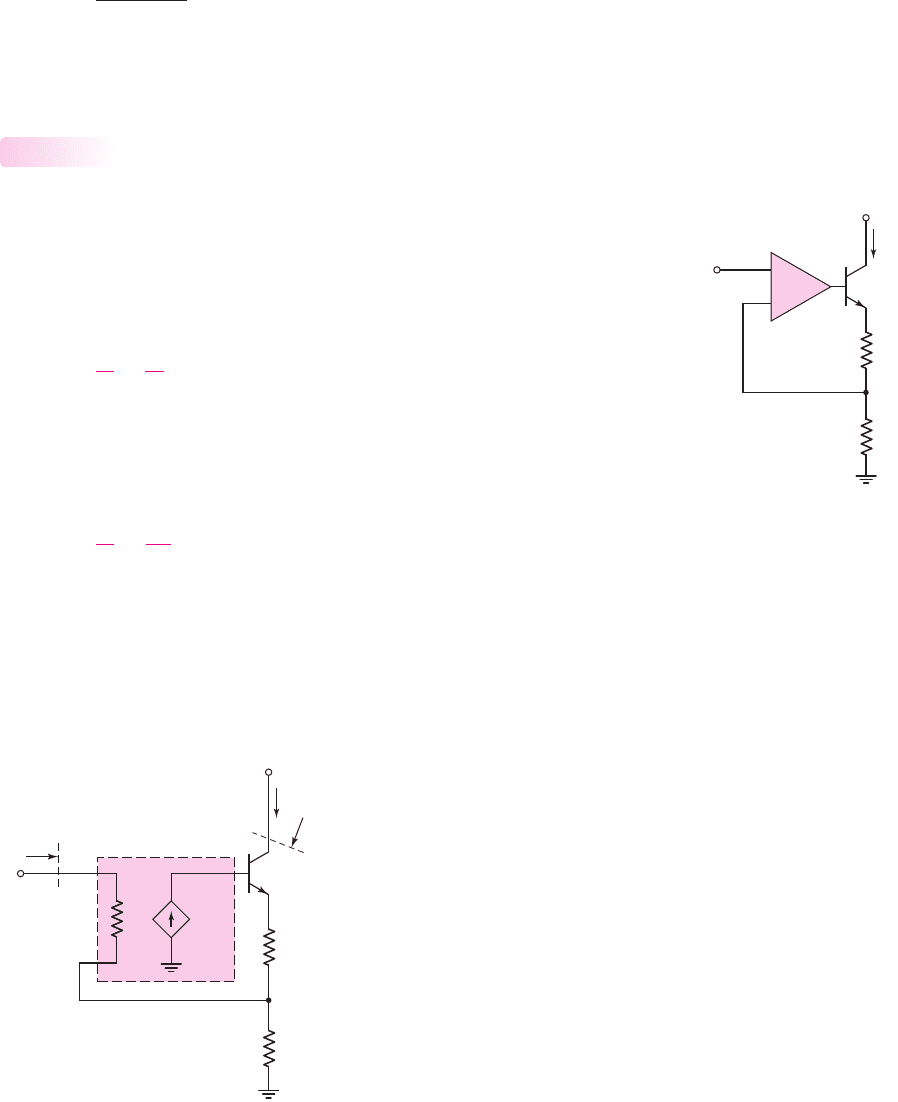
12.6 TRANSCONDUCTANCE (SERIES–SERIES)
AMPLIFIERS
Objective: • Analyze op-amp and discrete transistor circuit examples
of series–series (transconductance) feedback amplifiers.
In this section, we will analyze an op-amp and a discrete circuit representation of the
series–series feedback amplifier. The series–series circuit is a transconductance
amplifier; therefore, we must derive the output current to input voltage transfer
nea80644_ch12_851-946.qxd 6/23/09 1:45 PM Page 886 pmath DATA-DISK:Desktop Folder:23/06/09:MHDQ134-12:
A
g
V
e
+
–
+
–
V
i
R
i
+
–
V
fb
R
L
V
e
R
if
V
CC
R
of
R
E
I
o
Figure 12.28 Equivalent circuit, op-amp series–series feedback configuration
function. For the ideal configuration, this function is, from Equation (12.39),
A
gf
=
A
g
(1 + β
z
A
g
)
where A
g
is the basic amplifier transconductance gain and
β
z
is the resistance feed-
back transfer function. We found that with this feedback configuration, both the input
and output resistances increase compared to the basic amplifier values.
Op-Amp Circuit Representation
The op-amp circuit in Figure 12.27 is an example of the series–series feedback
configuration. The input signal is the input voltage V
i
, the feedback voltage is
V
fb
,
and the error signal is the voltage
V
ε
. The series output connection samples the out-
put current, which means that the feedback voltage is a function of the output current.
In the ideal feedback circuit, the amplification factor A
g
is very large; therefore,
from Equation (12.39), the transfer function is
A
gf
=
I
o
V
i
∼
=
1
β
z
(12.70)
Assuming an ideal op-amp circuit and neglecting the transistor base current, we have
V
i
= V
fb
= I
o
R
E
and
A
gf
=
I
o
V
i
=
1
R
E
(12.71)
Comparing Equations (12.70) and (12.71), we see that the ideal feedback transfer
function is
β
z
= R
E
(12.72)
We can take a finite amplifier gain into account by considering the equivalent
circuit in Figure 12.28. The parameter A
g
is the open-loop transconductance gain of
12.6.1
Chapter 12 Feedback and Stability 887
V
CC
V
i
R
L
+
–
+
–
V
e
+
–
V
fb
I
o
R
E
Figure 12.27 Example of
an op-amp series–series
feedback circuit
nea80644_ch12_851-946.qxd 6/23/09 1:45 PM Page 887 pmath DATA-DISK:Desktop Folder:23/06/09:MHDQ134-12: