Roy K.K. Potential theory in applied geophysics
Подождите немного. Документ загружается.


11.6 Expressions for Potentials for Three Electrode Configuration 339
N are the two potential electrodes. AM(= D
1
), AN(= D
2
)andMNaredis-
tances between different electrodes. O is the mid point between M, N and
AO is considered the tool length. Return current electrode is considered at an
infinite distance. Expressions of potentials at different positions are given in
the following section.
Cases for Thick Bed (H > L):
Case 1:
φ
M
=
ρ
1
I
4π
)
1
D
1
+
K
12
(2Z − D
1
)
+(1− K
12
)K
23
∞
n=1
(K
21
K
23
)
n−1
(2nH + 2Z −D
1
)
*
(11.30)
φ
N
=
ρ
1
I
4π
)
1
D
2
+
K
12
(2Z − D
2
)
+(1− K
12
)K
23
∞
n=1
(K
21
K
23
)
n−1
(2nH + 2Z −D
2
)
*
(11.31)
Case 2:
φ
M
=
ρ
1
I
4π
)
1
D
1
+
K
12
(2Z − D
1
)
+(1− K
12
)K
23
∞
n=1
(K
21
K
23
)
n−1
(2nH + 2Z −D
1
)
*
(11.32)
φ
N
=
ρ
2
I
4π
(1 − K
12
)
)
∞
n=0
(K
21
K
23
)
n
(2nH + D
2
)
+K
23
∞
n=1
(K
21
K
23
)
n−1
(2nH + 2Z − D
2
)
*
(11.33)
Case 3:
φ
M
=
ρ
1
I
4π
ρ
2
I
4π
(1 −K
12
)
)
∞
n=0
(K
21
K
23
)
n
(2nH + D
1
)
+K
23
∞
n=1
(K
21
K
23
)
n−1
(2nH + 2Z −D
1
)
*
(11.34)
φ
N
=
ρ
2
I
4π
(1 −K
12
)
)
∞
n=0
(K
21
K
23
)
n
(2nH + D
2
)
+K
23
∞
n=1
(K
21
K
23
)
n−1
(2nH + 2Z −D
2
)
*
(11.35)
Case 4:
φ
M
=
ρ
2
I
4π
)
1
D
1
+K
21
∞
n=1
(K
21
K
23
)
n−1
{2(n− 1) H + 2Z + D
1
}

340 11 Electrical Images in Poten tial Theory
+K
23
∞
n=1
(K
21
K
23
)
n−1
{2(n− 1) H + 2 (H −Z) − D
1
}
+
∞
n=1
(K
21
K
23
)
n
(2nH + D
1
)
+
∞
n=1
(K
21
K
23
)
n
(2nH −D
1
)
(11.36)
φ
N
=
ρ
2
I
4π
)
1
D
2
+K
21
∞
n=1
(K
21
K
23
)
n−1
{2(n− 1) H + 2Z + D
2
}
+K
23
∞
n=1
(K
21
K
23
)
n−1
{2(n− 1) H + 2 (H − Z) −D
2
}
+
∞
n=1
(K
21
K
23
)
n
(2nH − D
2
)
+
∞
n=1
(K
21
K
23
)
n
(2nH −D
2
)
*
(11.37)
Case 5:
φ
M
=
ρ
2
I
4π
)
1
D
1
+K
21
∞
n=1
(K
21
K
23
)
n−1
{2(n− 1) H + 2Z + D
1
}
+K
23
∞
n=1
(K
21
K
23
)
n−1
{2(n− 1) H + 2 (H − Z) − D
1
}
+
∞
n=1
(K
21
K
23
)
n
(2nH + D
1
)
+
∞
n=1
(K
21
K
23
)
n
2nH − D
1
*
(11.38)
φ
N
=
ρ
3
I
4π
(1 − K
23
)
)
1
D
2
+
∞
n=1
(K
21
K
23
)
n
(2nH + D
2
)
+K
21
∞
n=1
(K
21
K
23
)n− 1
{2(n− 1) H + 2Z + D
2
}
(11.39)
Case 6:
φ
M
=
ρ
3
I
4π
(1 − K
23
)
)
1
D
1
+
∞
n=1
(K
21
K
23
)
n
(2nH + D
1
)
+K
21
∞
n=1
(K
21
K
23
)
n−1
{2(n− 1) H + 2Z + D
2
}
*
(11.40)
φ
N
=
ρ
3
I
4π
(1 − K
23
)
)
1
D
2
+
∞
n=1
(K
21
K
23
)
n
(2nH + D
2
)
+K
21
∞
n=1
(K
21
K
23
)
n−1
{2(n− 1) H + 2Z + D
2
}
*
(11.41)

11.7 Expression for Potentials for Seven Electrode Configurations 341
Case 7:
φ
M
=
ρ
3
I
4π
)
1
D
1
−
K
23
(2Z + D
1
)
− (1 − K
23
)K
12
∞
n=1
(K
21
K
23
)
n−1
(2nH + 2Z + D
1
)
*
(11.42)
φ
N
=
ρ
3
I
4π
)
1
D
2
−
K
23
(2Z + D
2
)
− (1 − K
23
)K
12
∞
n=1
(K
21
K
23
)
n−1
(2nH + 2Z + D
2
)
*
(11.43)
Special Cases for Thin Bed (H < L)
Case 4:
φ
M
=
ρ
2
I
4π
(1 −K
12
)
)
∞
n=0
(K
21
K
23
)
n
(2nH + D
1
)
+K
23
∞
n=1
(K
21
K
23
)
n−1
(2nH + 2Z −D
1
)
*
(11.44)
φ
N
=
ρI
4π
(1 − K
12
)(1− K
23
)
∞
n=0
(K
21
K
23
)
n
(2nH + D
2
)
(11.45)
Case 5:
φ
M
=
ρ
3
I
4π
(1 −K
12
)(1− K
23
)
∞
n=0
(K
21
K
23
)
n
(2nH + D
1
)
(11.46)
φ
N
=
ρ
3
I
4π
(1 −K
12
)(1− K
23
)
∞
n=0
(K
21
K
23
)
n
(2nH + D
2
)
(11.47)
Apparent resistivity (ρ
a
) is calculated point by point using the relation
ρ
a
=4π.
AM.AN
MN
.
∆φ
I
(11.48)
where, ∆φ = φ
M
− φ
N
and I is the current intensity.
11.7 Expression for Potentials for Seven Electrode
Configurations
Direct current response across the horizontal beds of contrasting resistivity
in an otherwise homogeneous and isotropic medium using vertically moving
seven electrode system in the absence of any borehole is computed to high-
light some points of principle. Seven electrode system assumed in this model

342 11 Electrical Images in Poten tial Theory
differs from Schlumberger later olog system on one point i.e., the bucking cur-
rent electrodes are not shorted to check the variation of I
1
/I
0
and I
2
/I
0
.The
potential electrodes M
1
,M
4
and M
2
,M
3
are shorted the way it is done in LL7
(Laterolog -7) Schlumberger Log Interpretation Principle (1972). Differences
in pot ential between M
1
,M
2
and M
3
,M
4
has been brought to the same level
by equating the potentials developed. To get the maximu m focusing all the
four po tentials are equated. Theory of electrical images are used for compu-
tation of potentials. This derivation is based on four points.
(a) Current through the central electrode
∧
A
0
can always be kept constant.
(b) It is po ssible to bring all the four potential electrodes in a same equipoten-
tial line by adjusting bucking currents. Bucking currents are the currents
I
1
and I
2
sent by two bucking or guard electrodes A
1
and A
2
(Fig. 11.3). To
avoid any current flow through the potential electrodes, they are instanta-
neously brought to the same potential by adjusting the bucking currents.
(c) By equating potentials develop ed in the four potential electrodes M
1
,M
2
,
M
3
and M
4
, we get four nontrivial equations for φ
M1
= φ
M2
, φ
M2
= φ
M3
,
φ
M3
= φ
M4
and φ
M4
= φ
M1
to solve for either two (I
1
and I
2
)orthree
((I
1
, I
2
and I
0
) unknowns for fixed or variable I
0
. Here two unknowns I
1
and I
2
are determined from four equations using the generalized inverse.
(d) Variable geometric factor is considered (Roy 1977) for computation of
apparent resistivity. A seven electrode system with a central focusing cur-
rent electrode
∧
A
0
and a pair of guard or bucking current electrod es
∧
A
1
and
∧
A
2
are considered. Two pairs of shorted potential electrodes M
1
M
4
and
M
2
M
3
are taken and mathematical shorting is done equating φ
M1
= φ
M2
and φ
M3
= φ
M4
. That ensures focusing of currents, i.e., the currents are
forced to flow in a particular direction in the form of a beam of current.
0
1
and 0
2
are respectively the mid points of M
1
M
2
and M
3
M
4
.
∧
A
1
∧
A
2
(= L) is the electrode separation. Most of the computations were done
with 0
1
0
2
=0.4L. Return current and potential electrodes are assumed to be
far away from the electrode system. Bucking current
∧
A
1
and
∧
A
2
are allowed to
remain open (not short circuited) and I
1
and I
2
are adjusted till the potentials
at M
1
,M
2
,M
3
and M
4
are made the same. Focussing current I
0
is kept fixed.
Apparent resistivity at each point is computed using the geometric factor for
laterolog system, i.e.,
ρ
a
=
4π
1
A
0
M
1
+
I
1
/I
0
A
1
M
1
+
I
2
/I
0
A
2
M
1
φ
M
1
I
0
(11.49)
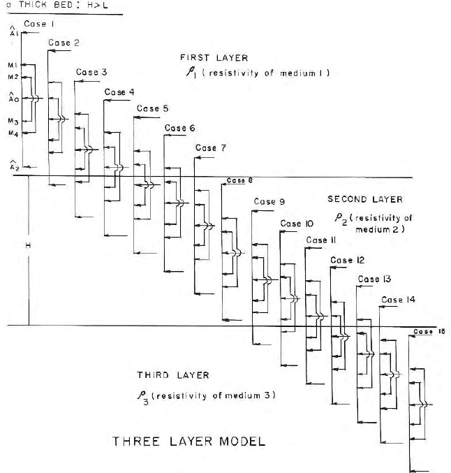
In total there will b e 36 cases for computation of potential for different
positions of the seven electrode system. 15 of them are for thick beds (H > L)
where H is the bed thickness and L is the electrode separation. Rest 21 cases
are for thin beds (not shown). The expressions for potentials for thick beds
11.7 Expression for Potentials for Seven Electrode Configurations 343
Fig. 11.4. Seven electrode laterolog – 7 is crossing the boundaries; 15 cases of
electrode positions and formations of images are presented
and only for case 1 (Fig. 11.4) are presented here as a sample. Since the
derivation of these expressions are quite simple and straight forward (Keller
and Frischknecht 1966 and Dakhnov 1962), the rest of the exercise is omitted
from the text.
Here X
11
,X
12
,..... X
43
are the coefficients of I
0
,I
1
and I
2
. These expres-
sions will differ for different cases. From equation (11.54) one can write
φ
M1
− φ
M2
=0=Y
11
I
0
+Y
12
I
1
+Y
13
I
2
(11.50)
φ
M2
− φ
M3
=0=Y
21
I
0
+Y
22
I
1
+Y
23
I
2
(11.51)
φ
M3
− φ
M4
=0=Y
31
I
0
+Y
32
I
1
+Y
33
I
2
(11.52)
φ
M4
− φ
M1
=0=Y
41
I
0
+Y
42
I
1
+Y
13
I
2
(11.53)

344 11 Electrical Images in Poten tial Theory
where,
Y
11
=(X
11
− X
21
), Y
12
=(X
12
− X
22
) (11.54)
Y
13
=(X
13
− X
23
), Y
21
=(X
21
− X
31
) (11.55)
Y
22
=(X
22
− X
32
), Y
23
=(X
23
− X
33
) (11.56)
Y
31
=(X
31
− X
41
), Y
32
=(X
32
− X
42
) (11.57)
Y
33
=(X
33
− X
43
), Y
41
=(X
41
− X
11
) (11.58)
Y
42
=(X
42
− X
12
), Y
43
=(X
43
− X
13
) (11.59)
Equation (11.50) to (11.53) can be written in a matrix form as
⎡
⎢
⎢
⎣
Y
12
Y
13
Y
22
Y
23
Y
32
Y
33
Y
42
Y
43
⎤
⎥
⎥
⎦
I
1
I
2
= −
⎡
⎢
⎢
⎣
Y
11
Y
21
Y
31
Y
41
⎤
⎥
⎥
⎦
I
0
(11.60)
In a matrix notation equation (11.65) can be written as
Y
1
=Y
′
I
0
(11.61)
Since a ll the four equation (11.55) to (11.58) are non trivial, the solution of
equation (11.66) for estimation of bucking currents can be obtained using the
least square estimator of a rectangular matrix (Draper and Smith, 1966) as
I=(Y
T
Y)
−1
(Y
T
I
0
)I
0
(11.62)
Here Y
T
is the transpose of Y.
With the help of these 9 equations (11.55) to (11.60) one can easily gen-
erate the potential expressions associated with four potential electrodes in
this seven electrode system. Potential generated at any position will be the
algebraic sum of potential developed due to the current flowing at different
current electrodes. As an example we can give expression for potential for case
1 for thick bed (h > L).
Thick Bed Case: 1
Using the list of symbols given in the next section, we can write the expressions
for potentials at all the four potential electrodes as
φ
M
1
=
ρ
1
I
1
4π
[E
1
+K
12
0
1
+(1− K
12
)K
23
A
1
]
+
ρ
1
I
0
4π
[E
5
+K
12
0
7
+(1− K
12
)K
23
A
7
]
+
ρ
1
I
2
4π
[E
9
+K
12
0
9
+(1− K
12
)K
23
A
9
] (11.63)

11.7 Expression for Potentials for Seven Electrode Configurations 345
φ
M
2
=
ρ
1
I
1
4π
[E
2
+K
12
0
2
+(1− K
12
)K
23
A
2
]
+
ρ
1
I
0
4π
[E
6
+K
12
0
8
+(1− K
12
)K
23
A
8
]
+
ρ
1
I
2
4π
[E
10
+K
12
0
10
+(1− K
12
)K
23
A
10
] (11.64)
φ
M
3
=
ρ
1
I
1
4π
[E
3
+K
12
0
3
+(1− K
12
)K
23
A
3
]
+
ρ
1
I
0
4π
[E
7
+K
12
0
5
+(1− K
12
)K
23
A
5
]
+
ρ
1
I
2
4π
[E
11
+K
12
0
11
+(1− K
12
)K
23
A
11
] (11.65)
φ
M
4
=
ρ
1
I
1
4π
[E
4
+K
12
0
4
+(1− K
12
)K
23
A
4
]
+
ρ
1
I
0
4π
[E
8
+K
12
0
6
+(1− K
12
)K
23
A
6
]
+
ρ
1
I
2
4π
[E
12
+K
12
0
12
+(1− K
12
)K
23
A
12
] (11.66)
Above expressions for p otentials (11.50) to (11.53), can be written in a short
form after separating out the terms of I
1
and I
0
and I
2
as
φ
M1
=X
11
I
0
+X
12
I
1
+X
13
I
2
φ
M2
=X
21
I
0
+X
22
I
1
+X
23
I
2
φ
M3
=X
31
I
0
+X
32
I
1
+X
33
I
2
(11.67)
φ
M4
=X
41
I
0
+X
42
I
1
+X
43
I
2
Computation for two electrode configuration for thick and thin bed (H > L)
are done following Roy and Rathi (1981) and Dutta (1993).
List of Symbols
E
1
=
1
D
11
;E
2
=
1
D
12
;E
3
=
1
D
13
;E
4
=
1
D
14
;E
5
=
1
D
21
;
E
6
=
1
D
22
;E
7
=
1
D
11
;
E
8
=
1
D
24
;E
9
=
1
D
31
;E
10
=
1
D
32
;E
11
=
1
D
33
;E
12
=
1
D
34
0
1
=
1
2Z
1
− D
11
;0
2
=
1
2Z
1
− D
12
;0
3
=
1
2Z
1
− D
13
;

346 11 Electrical Images in Poten tial Theory
0
4
=
1
2Z
1
− D
14
;
0
5
=
1
2Z
2
− D
23
;0
6
=
1
2Z
2
− D
24
;0
7
=
1
2Z
2
+D
21
;
0
8
=
1
2Z
1
+D
22
;
0
9
=
1
2Z
3
+D
31
;0
10
=
1
2Z
3
− D
32
;0
11
=
1
2Z
3
+D
33
;
0
12
=
1
2Z
3
+D
34
;
A
1
=
∞
n=1
(K
21
K
23
)
n−1
(2nH + 2Z
1
− D
11
)
;A
2
=
∞
n=1
(K
21
K
23
)
n−1
(2nH + 2Z
1
− D
12
)
;
A
3
=
∞
n=1
(K
21
K
23
)
n−1
(2nH + 2Z
1
− D
13
)
A
4
=
∞
n=1
(K
21
K
23
)
n−1
(2nH + 2Z
1
− D
14
)
;A
5
=
∞
n=1
(K
21
K
23
)
n−1
(2nH + 2Z
2
− D
23
)
;
A
6
=
∞
n=1
(K
21
K
23
)
n−1
(2nH + 2Z
1
− D
24
)
A
7
=
∞
n=1
(K
21
K
23
)
n−1
(2nH + 2Z
2
+D
21
)
;A
8
=
∞
n=1
(K
21
K
23
)
n−1
(2nH + 2Z
2
− D
22
)
A
9
=
∞
n=1
(K
21
K
23
)
n−1
(2nH + 2Z
3
+D
31
)
;A
10
=
∞
n=1
(K
21
K
23
)
n−1
(2nH + 2Z
3
+D
32
)
;
A
11
=
∞
n=1
(K
21
K
23
)
n−1
(2nH + 2Z
3
+D
33
)
;A
12
=
∞
n=1
(K
21
K
23
)
n−1
(2nH + 2Z
3
+D
34
)
where
K
12
,K
21
,K
23
are the reflection factors.
Z
1
,Z
2
,Z
3
are the distances of the current electrodes from the inter-
faces (Fig. 11.5).
D
11
,D
12
,D
13
,D
14
,D
21
,D
22
,D
23
,D
24
,D
31
,D
32
,D
33
,D
34
are
the distances between different current and potential electrodes
(Fig. 11.5).
H is the target be d thickness. The nature of seven electrode responses
across a three media formation is given in Fig. 11.4.
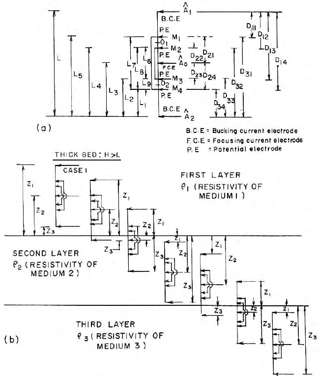
11.7 Expression for Potentials for Seven Electrode Configurations 347
Fig. 11.5. Different positions of the current and potential electrodes with respect
to the boundaries in a seven electrode laterolog seven system for computation of
potentials