Smith G.T. Cutting Tool Technology: Industrial Handbook
Подождите немного. Документ загружается.

trated in Fig. 155. In these diagrams a simplistic repre-
sentation for a range of cutting insert proles is shown
and for clarity, the tangential force has been excluded,
with just the axial and radial force components indi-
cated for each type of cutting insert shape. Assuming
that the overall cutting data is identical in each case
(i.e. the same: rotational speed, feedrate, D
OC
, insert
rake angle, plus workpiece material), then the only
variable in the longitudinal turning process here will
be the cutting insert shape its orientation. e com-
ponent cutting forces – axial and radial, will vary for
each tool prole in their respective magnitudes, due
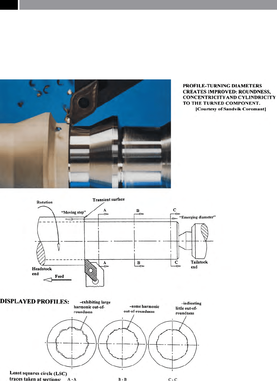
Figure 154. Machined roundness is inuenced by a number of factors: unbalanced cutting forces, non-integral headstock and
lack of support on slender/long workpieces
.
292 Chapter 7
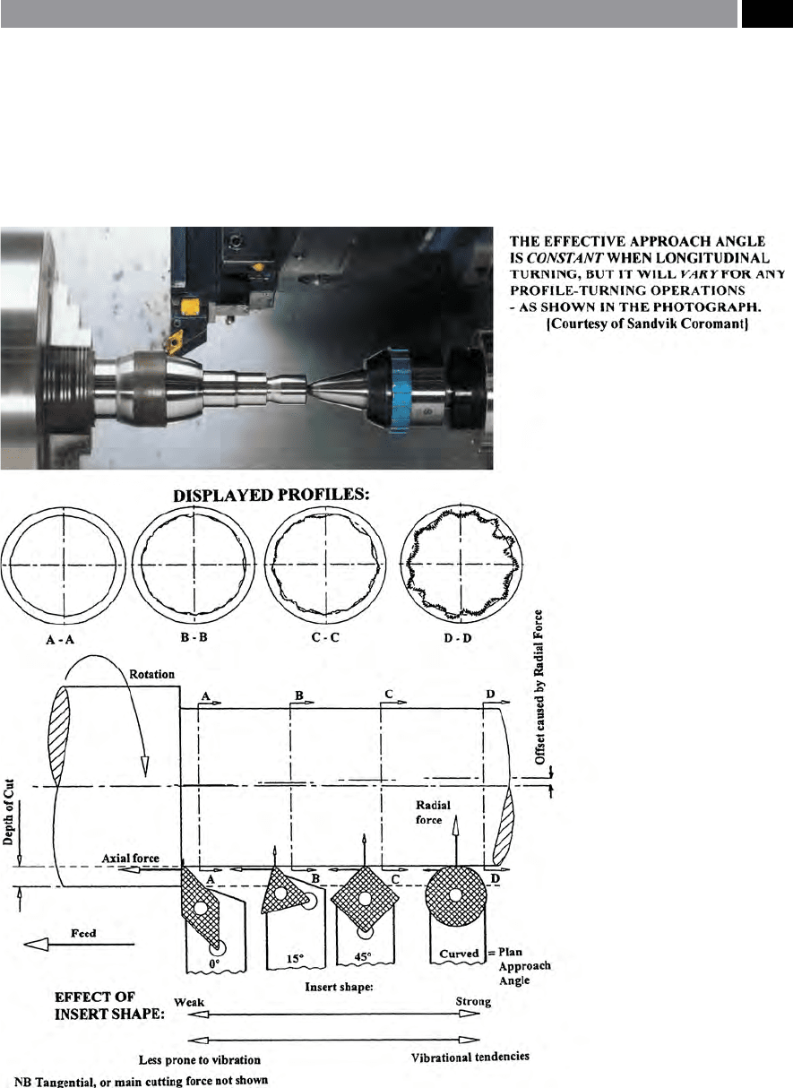
to the variation in plan approach angles. In the case of
the orthogonal insert (0°) plan approach angle, the ax-
ial force dominates with virtually no radial force com-
ponent present, this axial force being directly linked
with the feedrate. e displayed prole chart for this
harmonic roundness trace (i.e. section on ‘A-A’), for
the 0° plan approach angle, shows virtually negligible
harmonic eects. If a triangular-shaped cutting insert
geometry was selected, in this case having an 15° plan
approach, here there is a slight reduction in the axial
force component and a corresponding increase in its
radial counterpart. is slight increase in the radial
Figure 155. Turned roundness can be signicantly aected by the insert shape, its approach angle – which aects cutting forces
– resulting in harmonic out-of-roundness
.
Machinability and Surface Integrity 293

force, in combination with a marginally longer cut-
ting edge being in contact with the workpiece’s ‘tran-
si
ent surface’
26
, leads to a slight increase in the har-
monics on the displayed prole chart (‘B-B’). As the
o
bliquity of the insert’s plan approach angle increases,
as depicted by the square-shaped cutting insert, being
inclined at an angle of 45°, then the axial and radial
force components equalise. Here, the considerable
radial force component has a signicant eect on the
displayed prole trace, as illustrated by the section at
‘
C-C’ , where the harmonics have increased, but with a
notable vibrational tendency superimposed onto this
primary harmonic. is increase in vibration during
turning, is the result of two noteworthy factors: rstly,
the length of the transient surface has increased – with
this square insert’s greater plan approach angle; sec-
ondly, as a result of this rst condition of increased
obliquity, the radial force aects workpiece rigid-
ity, which is compromised, leading to an exacerbated
turned part surface roundness and accompanying
chatter-marks.
Finally, when turning with a round insert geometry,
this will lead to a vast increase in the radial force com-
ponent, which in turn may cause signicant harmonic
out-of-roundness, if a very rigid set-up is not utilised.
In this case, the round insert’s displayed prole trace,
shows evidence of a signicant increase in vibration
– chatter – present, which has a dramatic eect on
the prole of primary harmonic (section on ‘D-D’)
– more will be said on the subject of ‘chatter-marks’ on
the component’s surface shortly. e rationale for this
notable harmonic amplication when using round in-
serts is the product of several interrelated factors. e
transient surface in contact with the round/curved
prole has been markedly increased, together with the
plan approach at the tangency position – with respect
to the workpiece – being at a maximum; thus, the
combination these two factors leads to a momentous
deterioration in workpiece rigidity and as a result here,
the vibration will especially increase.
26 ‘Transient surface’ , can be dened as: ‘e part of the surface
formed on the workpiece by the cutting edge and removed dur-
ing the following cutting stroke, [by the next] revolution of the
tool, or workpiece’ (Boothroyd, 1975).
NB In the case thread-turning operations, the transient ank’s
surface only remains until the next pass of the screw-cutting
insert obliterates it, or until the nal thread depth is reached.
If a large volume of workpiece stock has to be re-
moved in a series of roughing cuts, a strong insert is
necessary, therefore the problem associated with the
harmonic behaviour of cutting insert geometry be-
comes of less importance. is latter fact allows either
a square, or round cutting insert to be utilised due to
their intrinsic strength and if vibration is a problem,
then a ‘nishing cut’ with an insert having an 0° plan
approach geometry would remove any probable sur-
face chatter-marks.
e case of turning with a round insert geometry is
worthy of a closer investigation, as several factors in-
uence the harmonic roundness of a workpiece turned
with its curved prole. For example, let us consider
several conditions for employing a standardised round
insert and its subsequent aect on the harmonics of
the turned part. If one assumes that an identical: ro-
tational speed, feedrate and workpiece material was
used, but having diering D
OC
’s – to isolate variabil-
ity in the turning process. In the rst example using a
small D
OC
, the radial force component is large in com-
parison to the axial force, but the harmonic workpiece
roundness is not compromised here – as these forces
are minute. Conversely, an extreme example of using
a round insert might be when employing a larger D
OC
.
Here, the radial force component has been reduced
in comparison to the axial component, although the
magnitude of these forces will be considerably greater
than in the former case. e pressure exerted on the
very long contact region at the transient curved sur-
face, creates potential harmonics in the turned part as
the resultant force has now signicantly increased. So,
the inuence of an increased D
OC
, in combination with
the round insert prole can create a very long contact
region at the transient surface, thereby causing un-
wanted harmonic eects on the turned surface.
In Appendix 9, a visual impression is given of the
principal techniques for roundness measurement and
its assessment, together with some of the ltering ef-
fects are highlighted.
7.3 Chatter in Machining
Operations
In the machining of metals, chatter (Fig. 156) is a form
of self-excited vibration introduced by the closed-loop
force-displacement response to cutting. e plastic de-
formation during machining operations is always pro-
294 Chapter 7

ceeded by elastic deformation – the situation is akin to
that of it acting somewhat like a ‘big spring’
27
. More-
over, the mechanism by which a cutting process dissi-
pates energy is termed chatter and vibration, also this
being a function of the workpiece’s rotational speed.
Any chatter/vibration can clearly be heard as an un-
wanted machining noise by an experienced machinist,
who would then modify the speed accordingly. ere
are a wide variety of causes for chatter, including the
process-induced eects from the cutting forces, which
may be the result of changes in: the cutting velocity;
chip cross-sectional area; tool/chip interface friction;
BUE, variations in the workpiece composition; or the
most common factor being process modulation result-
ing in regeneration of vibration. If greater energy is
input into the dynamic ‘machining-loop’ than can be
readily dissipated by the following: mechanical work;
damping, or friction, then an ‘equilibrium status’ is re-
quired and this output is via the somewhat superu-
ous eect of the generation of chatter/vibration.
Vibration is a debilitating process aecting both the
machined surfaces and reducing tool life in any ma-
chining operation, consequently it must be appropri-
ately identied – classied, then one has the potential
to nd the actual cause of this unwanted eect and
resolve it accordingly. In essence, in machining opera-
tions there are three types of vibration that may tran-
spire, these are:
•
Free vibration – this being the response to sudden
change, or to any initial condition, where the vibra-
tional amplitude decreases with time, occurring at
the system’s natural frequency,
NB
An interrupted machining operation, or work-
piece feature can create this vibrational eect and it
frequently appears as shadows, or lines following a
surface discontinuity.
•
Forced vibration – can be regarded as a response to
a periodic – repetitive timing – input that occurs at
an identical frequency. At this point, the vibrational
27 ‘Spring-cuts’ , are always present in any ductile component
machining operation, resulting from the relaxation of the
forces and the elastic recovery of the tool and workpiece aer
the cutting insert’s passage along the part. In fact, if the tool
is repositioned once more at the beginning of the original cut,
then simply fed along the component, it will take a minute cut
– assuming that the tool’s edge is still suciently sharp, this is
termed the ‘spring-cut’.
amplitude stays constant for a set of input condi-
tions, being non-linearly related to speed.
NB
e most common examples of this eect are
caused by: cutter imbalance, cutting teeth impact-
ing on workpiece, tooling misalignments, plus the
occurrence of any form of rotational system reso-
nance.
•
Self-excitation vibration, or chatter – occurs
through the system’s periodic response to a con-
stant input, which may intensify in amplitude – be-
coming unstable, oen occurring – regardless of
the input, but close to the natural frequency of the
system.
NB
Chatter is due to waviness regeneration in
the machined surface, it commonly occurs during
metal cutting operations (i.e. see Fig. 156a).
What is chatter and how might can be characterised?
Degarmo, et al. (2003), has produced a list of the fol-
lowing factors that can indicate the onset of chatter,
these being characterised by:
•
Sudden onset of vibration – whose amplitude will
rapidly increase until a maximum threshold – sat-
uration – is reached (i.e sounding like either: a
screech, whine, or buzz),
•
Chatter frequency is near to that of the machin-
ing system’s natural frequency (i.e critical fre-
quency) – changing only slightly with any process
parameter variations. e largest force-displace-
ment response occurs at ‘
resonance’
28
enabling the
maximum dissipation of energy,
•
Chatter produces unacceptable surface texture
(Fig. 156a) – normally highlighted by either an an-
gular, or helical pattern (i.e. the visual appearance
28 ‘Resonance’ , is of practical importance in many engineering
applications, because relatively few oscillatory forces can re-
sult in large vibrational amplitudes that can cause damage, or
interfere with the functioning of the system.
NB e classic example of this phenomenon was found when
ranks of soldiers marched across a bridge in unison (i.e. ‘in-
step’) which, if it coincided with one of the bridge’s resonant
frequencies, could create damage to the structure – despite the
fact that the bridge could safely support their overall weight.
Hence, the order to ‘break-rank’ (i.e randomising both their
pacing and steps) when proceeding over a structure such as a
bridge was mandatory.
Machinability and Surface Integrity 295
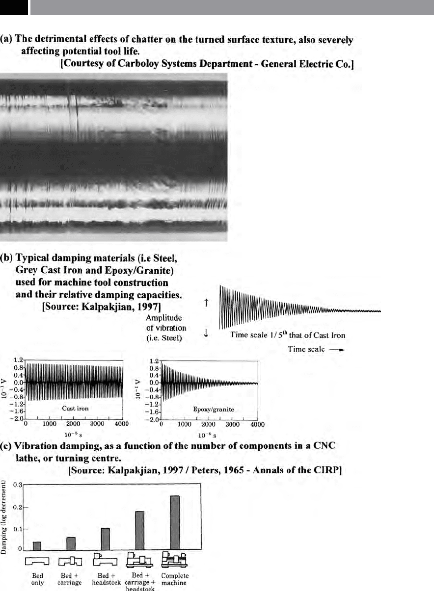
Figure 156. Vibration and chatter in machining operations, with their machine tool damping characteristics.
296 Chapter 7

is either ‘pearled’ , or ‘sh-scaled’) superimposed
over the normal cutting insert’s feed marks,
•
Visible surface undulations – these eects are re-
produced in the direction of feed, being the prod-
uct of either serrated, or wavy chip formations, of
variable thicknesses.
7.3.1 Chatter and Chip Formation –
Significant Factors Influencing
its Generation
e stability of the cutting process and the onset of re-
generative chatter is inuenced by a range of factors,
such as the: cutting stiness (K
s
)
29
of the workpiece
material – related to its machinability; parameters
of the machining process (e.g. speed, feed, D
OC
, chip
width – total); insert cutting geometry (e.g. rake and
clearance angles, edge preparation, insert shape and
size); cutting process dynamic characteristics (e.g.
machine-tooling-workpiece/xturing). Hence, during
machining operations on the workpiece, the chip is
formed by shearing over the chip area, producing the
cutting, or tangential force (F
T
). e magnitude of this
tangential force is heavily inuenced by the product
of the workpiece material’s stiness (K
s
) and the chip
area, as follows:
F
T
= K
s
× t × w
Where:
F
T
= tangential force (N),
K
s
= workpiece material’s stiness (N mm
–2
),
t =
chip thickness (mm),
w =
chip width (mm).
e direction of the tangential force (F
T
) is predomi-
nantly aected by the cutting insert’s rake and clear-
ance angles, together with the edge preparation on the
insert. In many single-/multi-point machining opera-
tions used to generate for example a milled surface,
there is a requirement to overlap the adjacent cutting
paths (Fig. 84c). For most single-point machining op-
29 ‘Cutting stiness’ (K
s
), is closely associated with that of ‘ow
stress’*, but is more simple to calculate and can be thought
of as a workpiece material property, being dependent on its
hardness.
*‘Flow stress’ , can be dened as: ‘e stress required to sustain
plastic deformation at a particular strain’ ( Kalpakjian, 1997).
erations, this former over-lapping of tool paths does
not take place in the same manner, but will only occur
aer one complete revolution of either the workpiece,
or tool. In operations by either milling (Fig. 85), or
drilling (Fig. 50), an overlap takes place in a fraction
of a revolution, this being dependent upon how many
cutting edges are present on the tool.
In the Degarmo, et al. (2003) machining model
shown in (Fig. 157a), the cutting or tangential force
(F
c
)
30
generation may cause a relative displacement ‘X’
between the cutting insert and the workpiece, aecting
the uncut chip thickness (t), this results in changing
the cutting force. is coupled relationship between
displacement in the ‘Y’ direction – modulation direc-
tion – and the resultant cutting force, creates a closed-
loop response system. Here, the modulation direction
is normally at 90° to the machined surface, so denes
the chip thickness. As a consequence of these inter-
related factors, there is a phase-shi (ε) between the
subsequent overlapping machined surfaces, resulting
in a variable chip thickness and modulation of the
displacement, causing chatter vibration to take place.
Accordingly, this phase-shi between overlapping cut-
ting paths is accountable for the production of chatter
(Fig. 157b). Moreover, there is a favoured speed cor-
responding to a phase-locked condition (e.g. when
‘ε=0’), resulting in a constant chip thickness (t). By
obtaining a constant chip thickness, this results in a
‘steady-state’ cutting force generation with it and, the
eradication of the feed-back mechanism for regenera-
tive chatter. In essence, this is the goal for all machin-
ing operators, as they attempt to achieve this eect by
vary the cutting speeds for a given set of conditions for
a particular machining operation.
7.3.2 Chatter – Important Factors
Affecting its Generation
In the previous sections, a brief discussion was made
concerning just some of the causes of regenerative
chatter mechanisms. It is worth looking in greater de-
tail at the reasons why this superuous chatter occurs,
explaining how and why it is generated in the hope of
30 In the Degarmo, et al. (2003) model diagrammatically shown
in Fig. 157a, they use the term and nomenclature of: ‘cutting
force’ and ‘F
c
’ , whereas previously in the text, this has been
referred to as the ‘tangential force’ , denoted by ‘F
T
’.
Machinability and Surface Integrity 297
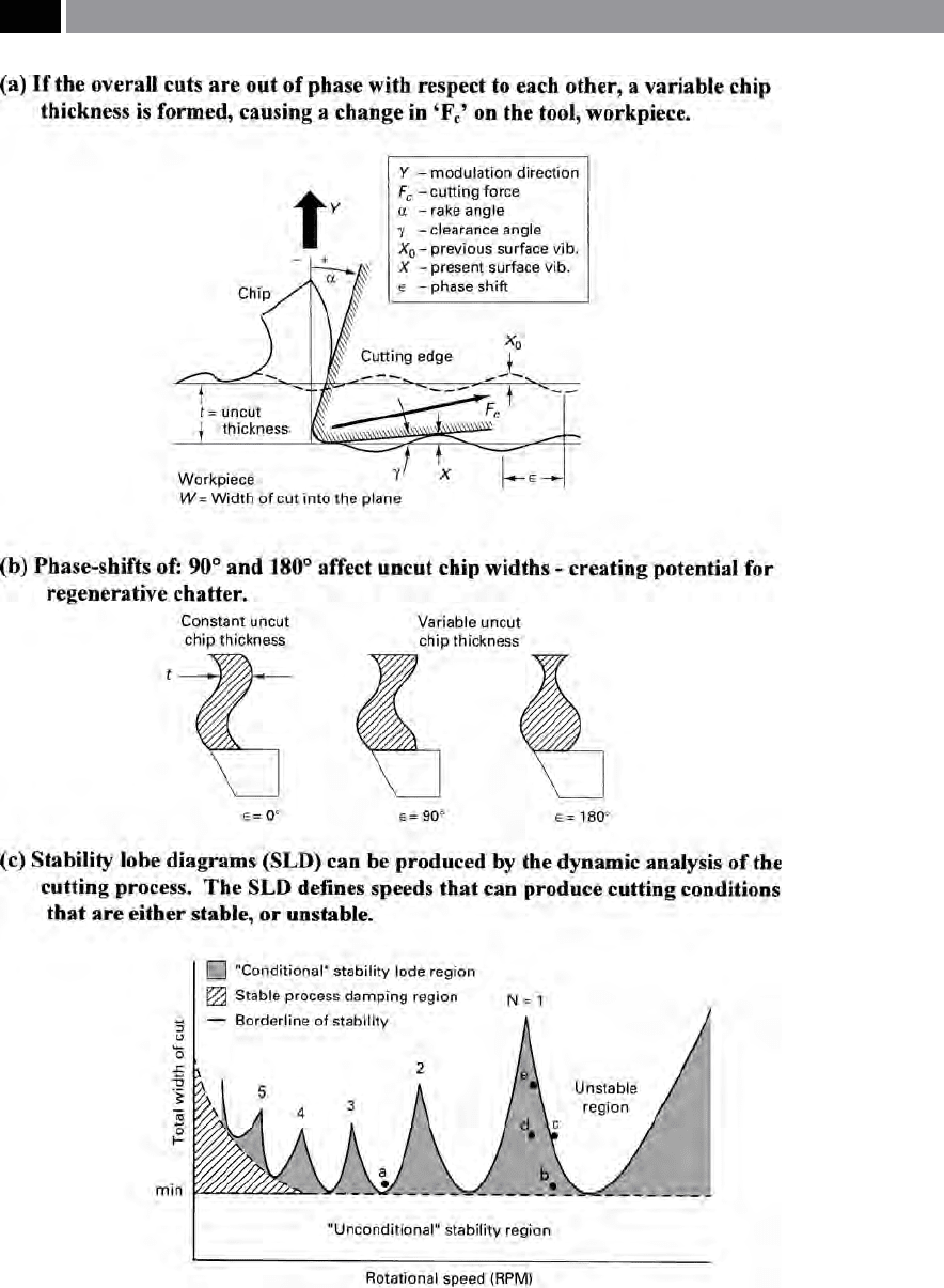
Figure 157. A chatter model, with potential chatter conditions and the application of the ‘stability lobe
diagram’. [Source: Degarmo, Black & Kosher, 2003]
.
298 Chapter 7

either entirely eliminating it, or at the very least, min-
imising its aect on the overall machining process.
Chatter during machining can result from a range of
multifarious and oen linked-factors, they include:
•
Depth of cut (D
OC
) – can be considered as the prin-
cipal cause and, for the prospective control of chat-
ter. e D
OC
delineates the chip width, acting as
the feed-back gain
31
within the closed-loop cutting
process,
NB
e machining processes ‘stability limit’ – be-
ing the threshold between stable cutting and chat-
ter – can be determined from trial-and-error by
simply incrementally increasing the D
OC
until the
commencement of chatter, then‘backing-o’ at this
level. e prediction of chatter’s onset can be found
analytically, this value being based upon thorough
knowledge of material stiness and cutting system
dynamics.
•
Rotational speed – is probably the simplest param-
eter to modify, thereby altering chatter and its as-
sociated amplitude,
NB
e peripheral speed of either the rotating
tool, or workpiece, aects the phase-shi between
overlapping surfaces and its associated vibration
regeneration.
•
Feed – for milling operations the feed per tooth de-
nes the average uncut chip thickness (t), inuenc-
ing the magnitude of the cutting process. Chatter
is not unduly aected by the feedrate selected, but
feed does have an eect on the predictable severity
of vibration during machining,
NB A
s no cutting force exists if the vibration oc-
curs in the ‘Y’ direction – resulting in loss of con-
tact between the tool and workpiece – the maxi-
mum amplitude of chatter vibration will be limited
by its feed.
31 ‘Gain’ , can be practically dened in the following way: ‘e
ratio of the magnitude of the output of a system with respect
to that of the input – the conditions of operation and measure-
ments must be specied’ (Smith, 1993, et al.).
•
Cutting stiness (K
s
) – is a material property con-
nected to: shear ow stress; hardness, as well as
work-hardening characteristics of the workpiece,
this factor oen being referred to in a metaphorical
sense of its material’s machinability characteristics,
NB M
aterials that might oer poorer comparative
machinability, for example titanium, require con-
siderably higher cutting forces leading to a greater
displacement in the ‘Y’ direction and as such, oer
a less stable cutting action.
•
Width of chip (total) – is equivalent to the product
of the D
OC
multiplied by the number of cutting edges
engaged in the cut. Furthermore, the total cut width
will inuence the stability of the cutting process,
NB A
t a preset D
OC
corresponding to that of the
‘stability limit’ , increasing the number of engaged
cutting edges, will result in chatter, or vice-versa.
•
Cutting tool geometry – inuences both the direc-
tion and the magnitude of the cutting force, in
particular the quantity of the force component in
the modulation direction ‘Y’. So, an increased force
occurring in the ‘Y’ direction, causes amplied dis-
placement and vibration at 90° to the surface, creat-
ing ideal conditions for chatter. Other cutting insert
geometrical factors that can inuence the cutting
stability include the following:
–
Back rake angle (α) – as it is inclined to a more
positive angle, the length of the commencement
of the shearing zone decreases, this in turn, re-
duces the magnitude of the cutting force (F
c
). As
the back rake inclination becomes larger, then
this directs the cutting force in a more tangential
manner, thereby reducing the force component
in the ‘Y’ direction – creating improved stability
at higher speeds,
NB A
n insucient feedrate in comparison to the
insert edge radius produces a less ecient cutting
action, with more tool deection and reduced ma-
chining stability.
–
Clearance angle – reduction (γ) – has the eect
of increasing the frictional contact at the inter-
face between the tool and workpiece, possibly
having a process damping eect. is potential
stabilising eect could be the result of energy
Machinability and Surface Integrity 299

dissipation – heat transformation, which could
result in decreased tool life, with the superu-
ous eect of thermal distortion of the machined
part, or an increase in the workpiece’s heat-af-
fected zone (HAZ),
NB O
n a newly-tted cutting insert, if initial wear
occurs, this can sometimes have a stabilising eect
for the onset of chatter.
–
Nose radius – size, insert shape – diamond tri-
angular, square, round, plan approach angle
– positive, neutral, negative – all inuence the
area of the chip shape and its corresponding ‘Y’
direction. e orientation of the modulation
direction ‘Y’ toward a dynamically more-rigid
direction angle, allows a decrease in vibrational
response, giving greater overall process stability
– having notably less chattering tendencies.
As machining process stability is a direct result of
characteristics of dynamic force displacement between
both the workpiece and the cutting insert, all of the
various factors of a machining system: machine tool;
spindle; tooling; workpiece; workholding – in varying
degrees, can inuence chatter. To increase process sta-
bility of the machining system, it is necessary to maxi-
mise the dynamics, this being the overall product of its
static stiness and damping capacity. Further, machin-
ing stability can be increased by utilising tooling with
the greatest possible diameter with the minimum of
tool overhang. By way of a caution concerning chatter
frequency, this normally occurs near the most exible
vibrational mode of the machining system.
7.3.3 Stability Lobe Diagrams
In Fig. 157c, a ‘Stability lobe diagram’ (SLD) is de-
picted, which relates to the: total cut width that can be
machined, to the tooling’s rotational speed, for a speci-
ed number of cutting inserts. For example referring
to the: Degarmo, et al. (2003) diagram, suppose the
total width of cut was maintained below a minimum
level
32
, then the process stability would exhibit ‘speed
32 If the total cut width was maintained below a minimum level,
in practical terms this would be of limited value for many ma-
chining systems.
independence’ , or an ‘unconditional stability’. Hence,
at relatively slow speeds an increased stability can
be achieved within the process damping region – as
shown. e ‘conditional stability’ lobe regions of the
diagram, permit an increased total cut width (i.e the
D
OC
x number of cutting edges, these being engaged
in the cut) at dynamically preferred speeds, at which
the phase-shi ‘ε’ between overlapping, or consecutive
cutting paths approaches zero. In Fig. 157c, stability
lobe number ‘N’ refers to the complete vibration cycles
existing between overlapping surfaces. Moreover, the
higher speeds correspond to lower lobe numbers, pro-
viding the utmost potential increase in the total cut
width and material removal rate – this being due to
the greater lobe height and width. If the total cut width
exceeds the stability threshold – even assuming that
the cutting process is operating at the desired speed,
chatter will occur. So, the larger the total cut width
a
bove the ‘stability limit’ , the more unstable and ag-
gressive the chatter vibration becomes.
Referring to the diagrammatic representation of
the SLD on the graph in Fig. 157c, if a chatter con-
dition arises, such as that found at point ‘a’ ,
the ro-
tational speed is attuned to the initial recommended
speed (i.e. when ‘N
=1’), resulting in stable machining
at point ‘b’ on this diagram. e D
OC
can be incremen-
tally increased until the onset of chatter again – as the
threshold stability is crossed at point ‘c’. By utilising a
hand-held ‘speed analyser’
33
whilst the chatter contin-
ues – under the previously-selected operating condi-
tions, this will result in the ‘analyser’ giving a modied
speed recommendation that corresponds to point ‘d’.
Now, if required, the D
OC
can be progressively incre-
33 ‘Speed analysers’ , are normally hand-held devices that pro-
duce dynamically-favoured speed recommendations and are
commercially available. Such ‘speed analyser’* equipment
when utilised for a cutting process, can show the relative mo-
tion between the tooling and the workpiece and recommends
the appropriate speed to avoid chatter-eects.
*‘Speed analysers’ can be successfully used for many industrial
applications, such as those involving: High-speed; in-chip,
hardened-die machining; multi-point cutting operations –
milling, etc.; Turning and boring operations. ese ‘speed anal-
ysers’ can also be employed for workpiece compositions rang-
ing from ductile metals (i.e. aluminium and steel grades) and
brittle materials (i.e. cast irons and brasses, etc.), together with
some non-metallics (plastics, etc.) and composite materials
(carbon bre, etc.).
300 Chapter 7

mentally increased to point ‘e’
34
– this being a ‘safe-
limit’ for the optimum machining operation.
7.4 Milled Roundness –
Interpolated Diameters
Circular features such as bosses, circular rebates, etc.,
can be CNC milled by utilising a specic word-ad-
dress ‘
circular interpolation’
35
command. is CNC
function creates precise and accurate circular control
in two slideways simultaneously, while the milling
cutter mills around the workpiece, as depicted in Fig.
158. Here, the milling cutter’s rigidity plays an impor-
tant role in the quality of the nal machined feature,
this being based upon the ‘
rigidity square rule’
36
. e
deected milling cutter illustrated in Fig. 158-right,
having lack-of-rigidity will produce some unwanted
eects on the nal milled part. Cutter deection not
only introduces the potential for chatter vibration,
but if used to mill up to square shoulder, its deection
distorts the component geometry and introduces har-
monic variation to the circular interpolated feature.
So that minimal change takes place in a milled prole,
it is advisable to keep to cutter lengths having short
34 Generally-speaking, it is not advisable to attempt to maintain
both the D
OC
and the total cut width at the stability thresh-
old , because any variation in the: workpiece aecting its cut-
ting stiness ‘K
s
’; speed errors; or perhaps small changes in
the overall dynamic characteristics of the machining system,
could result in crossing the stability limit, creating severe
chatter. For example, in a milling application, the amplitude
of chatter vibration can be limited by a provisional feed per
tooth reduction , until an established and desired speed has
been achieved oering a stable D
OC
.
35 ‘Circular interpolation’ ,
is a block of entered information di-
recting the CNC system to cut, either an arc, or a circle, (e.g.
G02 – in a clockwise, or G03 anti-clockwise direction).
36 ‘Rigidity square rule’ – for milling cutters states: ‘Cutter rigid-
ity decreases by the ‘square’* of the distance from the holder’
(Smith, 1993, et al.).
*
For example, if a cutter ‘stood-out’ from its respective tool-
holder by 50 mm to mill a circular feature (Fig.158 – le), then,
if all other machining conditions remained the same and, then
cutter was replaced by one of 100 mm long (Fig. 158 – right),
it would now be 4 times less rigid, causing serious tool deec-
tion.
stand-o distances, conducive with correct and cur-
rent operational practices.
ere are several distinct problems involved in the
milling high-quality circular interpolated features and,
a slight digression into basic machine tool induced-er-
rors is necessary to clarify the circumstances for the
problems exhibited in Fig. 159. Most of today’s ma-
chine tools have what is termed ‘orthogonally-orien-
tated axes’
37
and in the case of the popular three-axis
vertical machining centre congurations, if the axes
have not been recently calibrated, then considerable
‘error’
38
can be introduced into the nal milled part
features. It has been well-proven that a machine tool
equipped with three orthogonal sideways: ‘X-axis’;
‘Y-axis’ – in the horizontal plane, together with the
‘Z-axis’ – in the vertical plane, can introduce up to 21
kinematic ‘errors’ into the cutting process. e kine-
matics for any machine tool are quite complex, when it
has the ability to provide motion to all its axes simulta-
neously, although these errors are oen small, they are
37 ‘Orthogonally-orientated axes’ , (is briey mentioned in Foot-
note 2) refers to the fact that each axis is positioned at 90° with
respect to each other, oen situated on top of another axis.
For example, on a typical 3-axis vertical machining centre,
the ‘Y-axis’ sits on top of the ‘X-axis’ , but at right-angles to it,
conversely, the ‘Z-axis’ is situated at 90° to these axes – hence
the term ‘orthogonal’.
NB Non-orthogonal machine tools exist, oen having com-
plex ‘kinematics’* between ve and six axes. erefore with
these machine tools, in order to machine (i.e. mill) a straight-
line. all the axes must be in synchronised control to achieve
this linear action.
*Kinematics, comes from the Greek word ‘Kinesis’ , which
means ‘Motion’. It can be dened as: ‘e study of motion with-
out regard for the cause‘ (Lombardi, 2001). In machine tool
terminology, it refers to the translational eects of both lin-
ear and angular motions. It is principally concerned with the
eects of the ‘degrees of freedom’ for a ‘free-body’ in three-di-
mensional space (also see: Footnote 47, in Chapter 3).
38 ‘Error’ is now not considered as an appropriate metrological
term for any form of calibration, the recommended term to-
day, is: ‘uncertainty’*.
*‘Uncertainty’ , has been simply dened as: ‘e doubt that
exists about the result of any measurement’ (Bell/NPL, 1999).
is is why today, uncertainty in measurement is a combina-
tion of many factors, some physical, while others are induced.
Hence, another term, along with all of these uncertainty fac-
tors has been coined, which is its ‘Uncertainty budget’ – this
being a simple mathematical calculation, based upon a sum-
mary of these uncertainty calculations.
Machinability and Surface Integrity 301