Smith G.T. Cutting Tool Technology: Industrial Handbook
Подождите немного. Документ загружается.

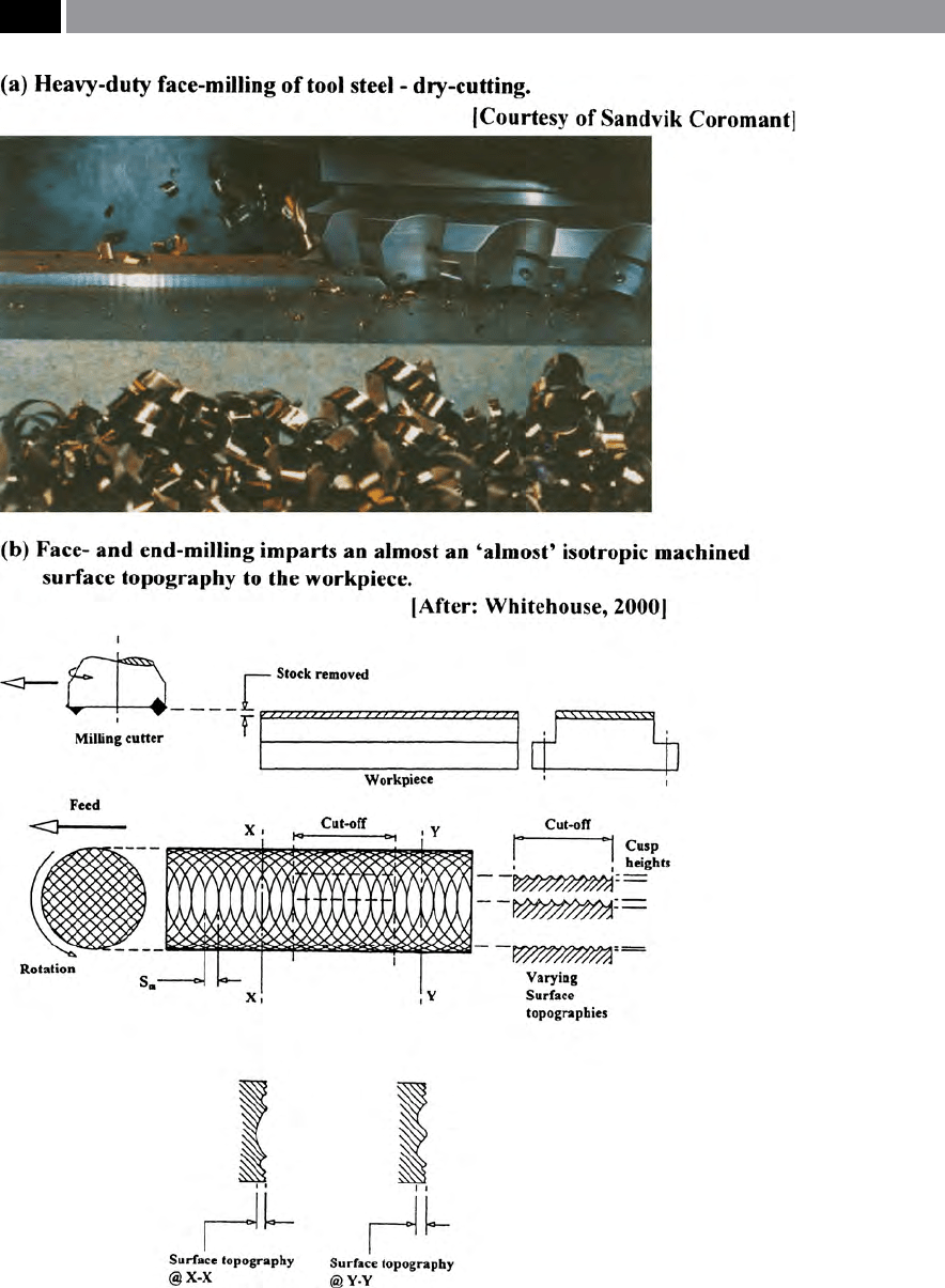
Figure 168. In face- and end-milling operations, due to the ‘re-cutting eect’ of the trailing insert cutting
edges, they impart an ‘almost’ isotropic milled surface topography to the part
.
322 Chapter 7
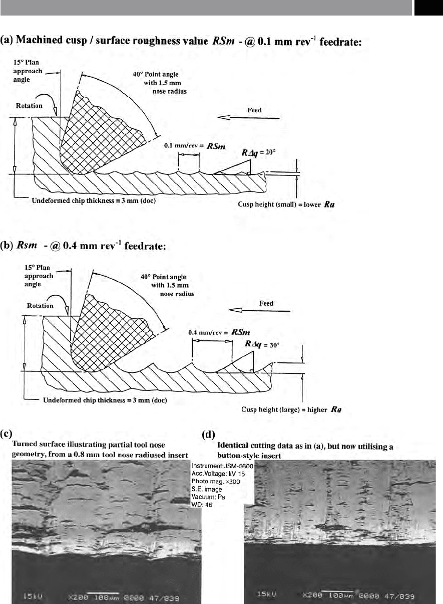
Figure 169. How the feedrate inuences the machined
cusp/surface roughness value ‘Sm’ and its aect on the wavi-
ness parameter ‘Δq’, plus surface topography of actual longi-
. tudinal CNC turned P/M ferrous compacts – cut with diering
nose radii. [Courtesy of Joel (UK) Ltd.]
Machinability and Surface Integrity 323

the considerably larger eective tool nose radius, act-
ing like a ‘wiper-blade’ blending-out and obliterating
the surface’s cusps. is technique of utilising a large
tool nose geometry has traditionally been used by pre-
cision turners to improve the overall surface nish.
7.5.3 Manufacturing Process
Envelopes
e principal features of manufacturing process en-
velopes and indeed, for many amplitude distribution
curves is that they can be approximated by the so-
called ‘beta-function’ – ‘β’ (Fig. 170a). Here, the func-
tion has two parameters that are independent of one
another enabling them to be used as a means of sur-
face characterisation. e notation ‘a’ is the allocated
weighting for the prole ordinates measured from the
lowest valley and above, with notation ‘b’ being given
to weighting the prole from the highest peak down.
Hence, peaks and valleys have accordingly dierent
weights. One of the problems that has arisen from util-
ising this technique for a topographical prole, which
has somewhat discredited them for certain applica-
tions, is how and in what manner can one determine
‘a’ and ‘b’.
e ‘beta-function’ is normally dened within a set
range of: 0→1, being expressed in the following man-
ner:
β(a, b) =
�
z
a−
(a − z)
b−
dz
.
If by changing the range of the ‘beta-function’ equa-
tion above, from: 0→1 to Rp + Rv, or indeed with that
of Rt, then substituting σ (i.e. the standard deviation
of the distribution) with Rq, the beta-function param-
eters ‘a’ and ‘b’ become:
a = Rv (Rv Rp – Rq
2
/Rt Rq
2
)
b = Rp (Rv Rp – Rq
2
/Rt Rq
2
).
e fact that any dominant peak, or valley within the
assessment length is only raised to a unit power, in-
fers additional stability over the ‘skewness/kurtosis ap-
proach’. e problem with this ‘beta-function’ method
is in accurately determining ‘sound’ results from the
Rv and Rp, which conrms the diculty that obtain-
ing information from peak/valley measurement and
then deriving valid information is fraught with com-
plications. In Figs. 170: ‘ai’ it is symmetrical; with ‘aii’
being asymmetrical; for their respective ‘beta-func-
tions’ , these relationships are based upon a class of sta-
tistically-derived ‘Pearson distributions’
59
. In the sym-
metrical case (Fig. 170ai) the skewness equates to zero;
conversely, for an asymmetrical series of results (Fig.
170aii), skewness can be either positively, or negatively
skewed (i.e see Fig. 164bii). Nevertheless, even allow-
ing for these limitations, an example of the groups of
manufacturing process envelopes for a range produc-
tion processes is illustrated in Fig. 170b. Here, the pro-
duction processes can be simplistically classied and
grouped into either a ‘bearing’ , or ‘locking’ surface
topography. e ‘bearing-/locking-groupings’ indicate
that certain production processes can achieve specic
functional surfaces for particular industrial applica-
tions. ese ‘groupings’ (Fig. 170b), also indicate that
the general classications are less distinct than might
otherwise be supposed, as certain processes can be
provide either a ‘locking’ , or a ‘bearing’ surface condi-
tion – termed ‘intermediate groupings’. Typical of such
an ‘intermediate group’ are the P/M drilled compacts.
One reason for this is that any P/M ‘secondary ma-
chining’ oen utilises twist drills, which may produce
59 ‘Pearson product moment correlation coecient’* – to give
it its full title, is a statistical association utilised when a ‘rela-
tionship’ exists between several quantities and it is a measure
of the extent of this aliation, thus producing its ‘correlation
coecient’ which can then be utilised.
*For example, having a sample of pairs of observations ‘x’ and
‘y’ , the value ‘r’ of this ‘Pearson coecient’ , is given by the
‘generalised formula’ , below:
r = Σ(x – x ) (y – y) /√ Σ(x – x)
2
Σ(y – y)
2
(Bajpai, et al., 1979):
e calculated ‘Pearson coecient’ should lie either close
to –1, or +1. If the calculated value is close to –1 then the
‘straight-line trend’ is in a downward direction, conversely, if
the calculated value is close to +1 then the ‘straight-line trend’
direction is upward. If the value is close to zero (0), then no
correlation exists, so the pairing of the data is disparate and
cannot be utilised. With calculated data that is reasonably
close to either –1, or +1, a ‘regression line’ (i.e. using linear
regression) can be calculated based upon the general straight-
line formula:
Y = a + bX
Where a ‘regression line of Y on X’ for the two constants ‘a’ and
‘b’ respectively are:
b = nΣxy – (Σx)(Σy)/n(Σx
2
) – (Σx)
2
a = Σy – bΣx/n
Where a ‘regression line of X on Y’ for the two constants ‘a’ and
‘b’ respectively are:
b = nΣxy – (Σx)(Σy)/n(Σy
2
) – (Σy)
2
a = Σx – bΣy/n
NB e ‘regression line’ being the equivalent of the ‘least
squares line’ , allows data on each axes to be compared – with
some degree of condence.(Wild, et al.,1995)
324 Chapter 7
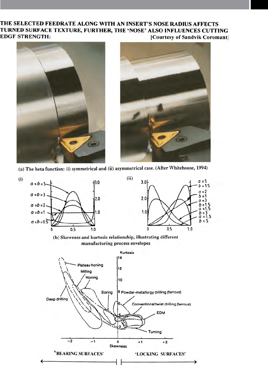
Figure 170. The ‘beta-function’ and typical ‘manufacturing process envelopes’.
Machinability and Surface Integrity 325

a ‘saw-toothed prole’ to the hole’s surface, along with
pores in the compact that are open to the ‘free-surface’
of the hole. e hole topography may have this ‘saw-
toothed eect’ present, it being a combination of the
drill’s partial lip and margin occurring at the feed rev
–1
periodicity, formed by the drill spiralling-down and
around the hole’s periphery. Hence, the drill’s passage
creates a positive skewness via drilled ‘saw-toothed
c
usps’ , while the pores can introduce negative skew-
ness – creating a potential ‘intermediate group’ to the
manufacturing process envelope groupings.
7.5.4 Ternary Manufacturing
Envelopes (TME’s)
In machining operations the dominant factor that in-
uences surface topography has been shown to be the
tool’s feedrate. In Fig. 171, the feedrate, in conjunc-
tion with the principal factors such as surface texture
(Ra) and roundness (i.e least squares circle – LSC), are
utilised to dene the limits for these ‘Ternary manu-
facturing envelopes’ (TME’s). By using such diverse
factors as: surface texture, roundness and processing
parameters (feedrate), for the major axes on the ter-
nary graph, enables the surface to be characterised in
a unique manner. Such TME’s dier quite consider-
ably from the more usual and restricted ‘manufactur-
ing process envelopes’ alluded to in the previous section
– the skewness and kurtosis axes of the manufacturing
envelopes, might otherwise mask crucial information.
e ‘TME approach’ gives a psuedo three-dimensional
representation on its ternary axes, which can be ex-
ploited to illustrate how the inuence of changing a
parameter – such as feedrate – modies the relation-
ship of the associated surface texture and roundness
values for the nal machined result.
As an example of the eectiveness of this TME ap-
proach to the complex problem of machining data
analysis, Fig. 171 has been drawn from an actual
machinability trial. If one observes this TME graph
closely for a pre-selected range of turning and boring
processes, indicated in Fig. 171, with specic reference
here, to turning operations – by way of illustrating
the TME’s expediency. e TME shows how – for the
tu
rning operations – at low feedrate (0.10 mm rev
–1
)
the surface texture is closely conned to a relatively
s
mall spread of values – nominally around 0.5-1.5 µm
Ra, whereas its associated roundness lies between
a
pproximately 5 and 50 µm LSC. As the feedrate in-
c
reased in an arithmetic progression to 0.25 mm rev
–1
,
the range of the surface texture bandwidth propor-
t
ionally expanded to 1.5 at approximately 5-6.5 µm
Ra, with a corresponding roundness ranging from 8 to
4
8 µm LSC, giving a proportional bandwidth of 1.6. As
t
he feedrate was raised even higher, to 0.40 mm rev
–1
,
it was not surprising to note that this also produced
increases in both the surface texture and its propor-
tional bandwidth, with similar values with respect to
its roundness. ese ‘machinability and metrology
trends’ allow examination of both the bandwidth vari-
ability and the aect of dierent feedrates on other
disparate factors – such as its machined roundness.
Similar trends occurred for the boring operation,
but here only two feedrates were employed, by applica-
tion of this analysis technique via the ‘TME-approach’
to a concise machinability trial, complex analysis of
the TME is possible. e pseudo three-dimensional
graph, oers perhaps an unusual insight into the mul-
tifaceted inter-relationships that exist aer workpiece
machining. e TME shows that simply examining
one metrological parameter in isolation to those that
could aect it, may mask vitally important relation-
ships and trends that would otherwise remain unseen.
By careful selection of the parameters for the respec-
tive axes, perhaps based upon the feedrate (i.e. here,
normally situated along the X-axis), allows an appre-
ciation of the whole surface at any instant along the
three graph’s axes.
7.6 Machining Temperatures
Ever since Taylor in 1907, recognised that elevated tool
and workpiece temperatures in metal cutting played
a crucial role in inuencing tool edge wear rates, the
subject has been one of intensive study. Moreover,
that the tool/chip interface temperature has a control-
ling inuence on the rate of crater wear and the fact
that tool life can be drastically curtailed by these in-
duced machining temperatures, as such, the topic has
received considerable research attention. Here, space
will only allow a brief resumé of this complex temper-
ature-induced machining problem.
During metal cutting in particular, there are sev-
eral temperature eects that need to be considered. In
Fig. 51, an orthogonal single-point cutting operation
is schematically illustrated, indicating the distribution
of heat sources within the three deformation zones. In
326 Chapter 7
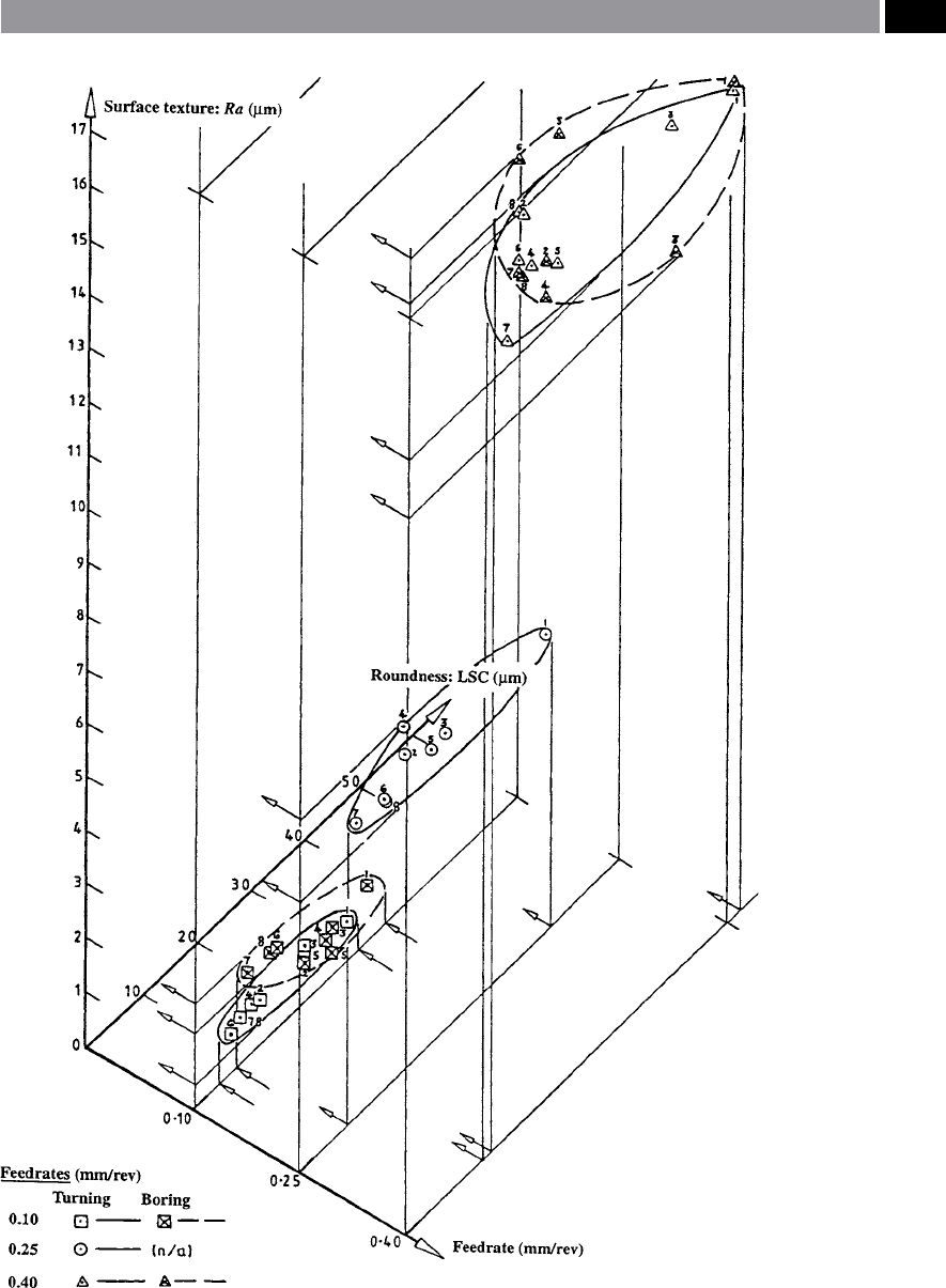
Figure 171. ‘Ternary manufacturing envelopes’ for the production processes of turning and boring,
axes: feedrate, roundness and surface texture
.
Machinability and Surface Integrity 327

particular, the heat generated in the main ‘body’ within
the cutting region via both the primary and secondary
zones is a result here, of the workpiece’s plastic defor-
mation. Still more intensive heat is generated at the
tool/chip interface – along the rake face, with the ma-
jority of heat being swept away with the chips, while
the remainder of heat is either conducted through the
tool, or conducted/convected into the workpiece. As-
suming that no coolant application is present in the
machining operation, then any heat loss to the ambi-
ent air becomes insignicant. An equation has been
developed that governs the temperature distribution –
via its isothermal gradients – in machining (Fig. 172),
this being an ‘energy-based equation’ as follows:
ρC(∂T�∂t + V � ∇T) − k∇
T −
˙
q =
(Source: Tay, et al., 1993).
erefore, in steady-state machining operations, the
transient term will disappear and at the region of the
tool (i.e. insert) only the conduction term remains.
∴ Rate of heat generation (˙q) = σ ˙ε
Where: ‘σ’ was obtained from an emprical function of:
‘ε’ , ‘˙ε’; plus ‘T’.
NB is rate of heat generation only exists within the
primary and secondary deformation zones.
By way of example of how the temperature genera-
tion/distribution occurs in orthogonal cutting, in the
more-easily understood ‘Boothroyd machining model’
(i.e. being in a slightly modied form – by the author),
this workpiece material is in a state of ‘continuous
motion’ during cutting (Fig. 172). If specic points
are selected to show how temperatures occur as they
pass along/through these deformation zones then,
the points: ‘X, Y and Z’ can be considered for special
observation. So, as the workpiece material enters the
cutting region at point ‘X’ , it begins to move toward
the cutting insert. It approaches and passes through
the primary deformation zone where it is heated-up
until it leaves this zone, it is then swept-away by the
formed chip. Equally point ‘Y’ , passes through both
the primary and secondary deformation zones (i.e
see Fig. 51 for these deformation zones) and contin-
ues to heat-up until it leaves the secondary deforma-
tion zone. In both of the above cases, these points (i.e.
namely: X and Y) are cooled as heat is conducted into
the chip’s body (as it exit’s the cut), where it eventually
achieves a uniform temperature right the way through.
Prior to this occurring, the maximum temperature
occurs along the cutting insert’s rake face, some dis-
tance from the actual cutting edge (i.e see Fig. 172).
Conversely point ‘Z’ , which remains attached to the
workpiece, is heated by conduction from the primary
deformation zone and some heat is also conducted
from the secondary deformation zone into the body
of the cutting insert, while the tertiary deformation
zone will also impart some heat into the machined
surface of the workpiece.
Many thermal and thermographical techniques
have been developed over the years to obtain accurate
isothermal temperatures within the: cutting zones:
tool/insert interface plus rake face vicinity; together
with the machined surface region of the workpiece.
Moreover, ‘indirect methods’ have been utilised to
obtain similar thermal historical data from within
these dynamic and harsh environments, but only one
of these techniques will be mentioned in the next sec-
tion.
7.6.1 Finite Element Method (FEM)
e popular approach today, to obtaining ‘simulated’
thermal data is by employing the ‘Finite element
method’ (FEM), to calculate temperature distributions
in the vicinity of the cutting regions (Fig. 173). Typical
of this approach and worth mentioning in some de-
tail, was that conducted and described by Tay (1993),
where he experimentally-obtained information re-
garding: velocity, strain and strain-rate distributions,
by utilising a printed-grid and quick-stop technique.
e rate of heat generation within the primary defor-
mation zone was determined from the equation:
(˙q) = σ ˙ε.
From the deformed grid pattern (Fig. 173a), the ac-
tual dimensions of the triangular deformation zone,
as well as the velocity distribution along the tool/chip
interface can be established and analysed. By this FEM
technique, it is possible to determine the shear-strain
rate within the secondary deformation zone at the
tool/chip interface:
(˙γ
int
) has been found to be approximately constant
and equal to: V
c/
δt
2
. e shear strain-rate within the
328 Chapter 7
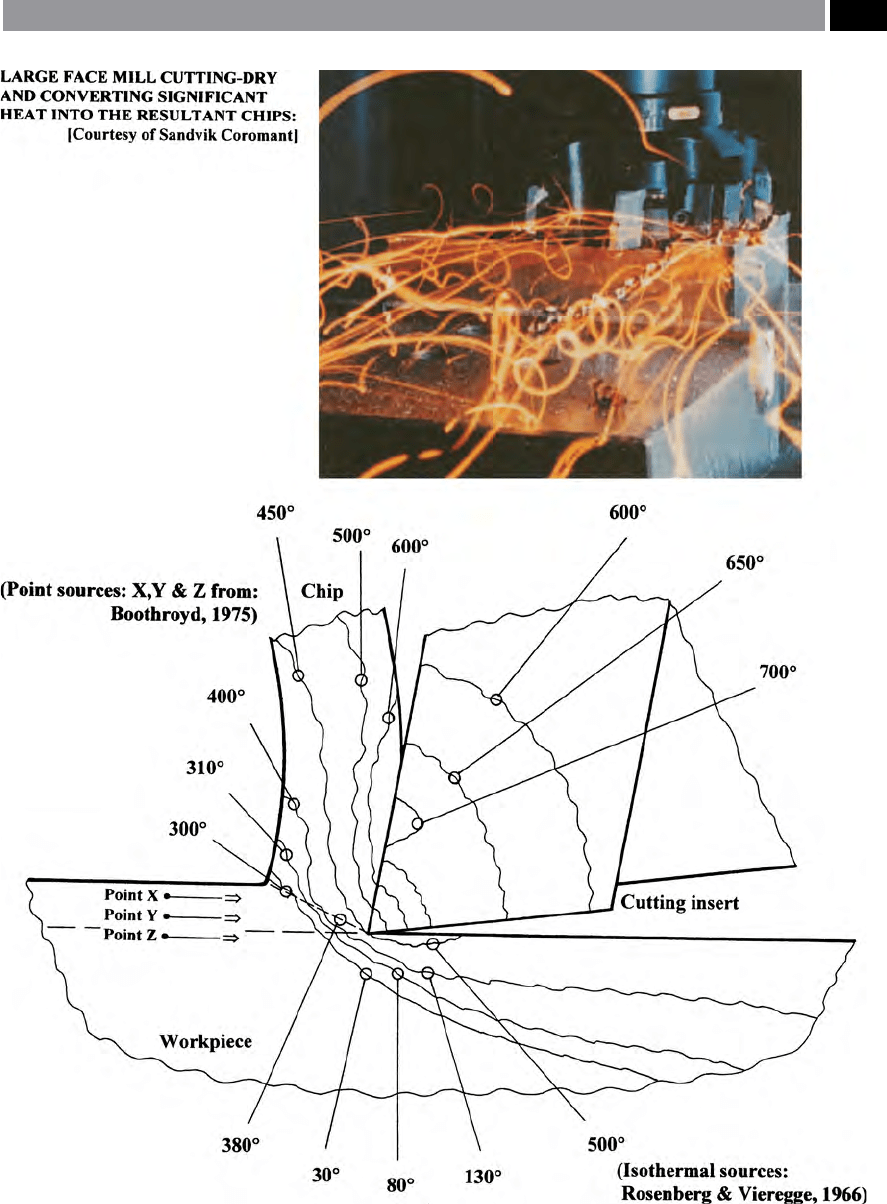
Figure 172. Typical temperature distributions (isotherms) during machining, illustrated across the: chip, insert and work-
piece; at relatively low cutting speed
.
Machinability and Surface Integrity 329

secondary deformation zone tends to be linear in na-
ture from:
(˙γ
int
) – at the interface, → zero – at the boundary of
the triangular secondary zone.
e frictional stress along the tool/chip interface
can be assumed to be constant along the rst half of
the contact region, then linearly decreasing to zero at
its end. e frictional heat source distribution at this
interface, can be obtained from stress and velocity dis-
tributions at this location.
In Fig. 173a, the basic ‘FEM mesh’ is shown, with
typical temperature distributions obtained from this
being illustrated in Fig. 173b. e accuracy of this
particular example for the ‘Tay-model’ for the total
sum of all heat sources was within 2.6% of actual mea-
sured power consumption (F
c
U). Moreover, the values
of ‘β’ calculated from the temperature distributions
closely-agreed to those obtained some years earlier
by Boothroyd (1963). e FEM approach to machin-
ing data capture and analysis covers these and other
related parameters and clearly indicates the power of
simulation – more will be mentioned on this subject
later in the chapter.
7.7 Tool Wear and Life
Introduction
e working environment for most machining pro-
cesses is extremely harsh, with pressures exerted
onto a minute area of tool tip being of the order of
>
1600 MPa, with localised temperatures reaching over
750°C creating a sterile surface at the tool/chip inter-
face, making this an ideal state for a pressure-welding
condition. In attempting to minimise this anity be-
tween the work-hardened chip – oen this plastic de-
formation making the chip >5 times harder than that
of the parent workpiece material, means that there are
several ways of relieving this tool/chip anity. e ob-
vious one is to use a cutting tool material that is in-
ert to the workpiece such as a either a: ceramic, or
mixed-ceramic cutting insert composition, or some-
thing similar, but this may not prove to be satisfactory,
particularly if interrupted cutting conditions are antic-
ipated. In this situation above, perhaps by utilising a
multi-coated cemented carbide insert this may reduce
this ‘adherence-tendency’. Lastly, the correct grade of
‘ood-coolant’ may: lower the interface temperature,
reduce friction here, while somewhat improving the
machined surface texture. When only partial success
is achieved by employing the above tooling strategies,
the last resort may be to adjust the cutting data to en-
hance and provide a ‘less-abusive machining regime’ ,
while simultaneously improving the ‘steady-state’ wear
conditions.
So far, no mention has been made here concern-
ing frictional eects in the cutting process. Friction is
very complex subject which relates not only to: chip
ow-stress and ‘
stiction’
60
problems at the chip/tool in-
terface, but concerns the tribological conditions along
this interface. Cutting tool rake and ank faces are
never perfectly smooth, as even when faces and edges
have been either been ground, or super-nished the
abrasive nature of the super-nishing process pro-
duces an abraded surface that approaches the grit size
of the abrasive medium. erefore, to the naked eye
the insert’s surface looks smooth, but at the ‘micron-
l
evel’ of surface magnication (i.e. 1 × 10
–6
m), the cut-
ting insert’s surface has localised ‘high-spots’ , or as-
perities present. ese asperities signicantly reduce
the contact area produced between the forming chip
and its contact at the interface on the tool’s rake face.
Not only can these asperities considerably decrease the
‘real area of contact’ and as a result increase the coe-
cient of friction here, but the asperities may be either
‘plastic’ ,
or ‘elastic’ in nature
61
. In Table 11 (i.e. exper-
imental data extracted from: Childs, et al., 2000, con-
cerning surface texture assessment of cutting insert
faces), comparison is made between a small sample of
60 ‘Stiction’ , is sometimes confused with its ‘close alternative’
this being: ‘stick-slip’. ese terms are worth stating, to ex-
plain their respective dierences and have been dened in the
following manner: ‘Stiction’ is: ‘e phenomenon at an inter-
face where the frictional stress is equal to the shear yield stress of
the soer material.’
‘Stick-slip’ is: ‘A jerky motion between sliding members due to
the formation and destruction of junctions.’ (Kalpakjian, 1984)
61 ‘Plastic asperities – on a plastic chip’ ,
these are ‘high-spots’
that will sink into the chip and how they achieve this action,
does not depend on local conditions at interface contact, but
on the bulk plastic ow eld. Specically, the lower the hydro-
static stress in the bulk ow eld, the less eort is required for
these asperities to sink.‘
Asperities – on an elastic foundation’ , this situation is ex-
tremely complex phenomena and put simply, in conditions of
low contact stresses, the chip beneath these asperities is elas-
tic. (Childs, et al., 2000)
330 Chapter 7

cutting insert surface conditions, clearly illustrating
that even when ‘
super-nishing’
62
an insert’s face it still
has asperities present.
7.7.1 Tool Wear
Introduction
On a single-point turning tool’s cutting insert, the
main regions of wear are normally conned to the:
rake face; ank; trailing clearance face; together with
62 ‘Super-nishing’ , is based on the phenomenon that a lubricant
of a given viscosity* will establish and maintain a separating
lm between two mating surfaces, if their roughness does not
exceed a specic value and, if certain critical pressure – keep-
ing them apart – is not exceeded. us, as minute peaks occur
on the cutting insert’s surface, they are then cut away by the
abrasive (e.g. minute diamond abrasive in a lubricant – oil –
suspension) this being applied with a controlled pressure –
until a required level of smoothness has been achieved.
NB e maximum stock removed from the insert will be ap-
proximately 50 µm.(Degarmo et al., 2003)
*Viscosity relates specically to oils, which will vary with
temperature. Dierent oils vary by dissimilar amounts for the
same temperature, this is why the ‘viscosity index’ (VI) has
been developed.
the actual nose radius (Fig. 174). Likewise, the type
of wear pattern provides important information as to
the eectiveness of the overall machining operation.
Considerable time and eort has been spent by both
researchers and tooling companies, ensuring that tool
wear mechanisms and their respective classications
for specic machining operations are understood. So,
by knowing the anticipated wear behaviour for a cut-
ting insert for a specic machining operation, this al-
lows the user to optimise productivity by ensuring that
the ‘ideal’ tool grade and its associated geometry, will
produce the desired machining conditions with the
correct type of cut for the chosen workpiece materi-
al’s composition. A range of factors can inuence tool
wear when component machining, these are: material
removal rate; ecient chip control; machining eco-
nomics, precision and accuracy demanded; plus the
machined surface texture requirements.
If one magnies then inspects the wear pattern on
a worn cutting edge, then it is reasonably straightfor-
ward to establish both the cause and remedy for the
indicated type of wear (i.e see Appendix 11), this will
allow subsequent tooling to be more adequately con-
trolled during following machining operations. In
o
rder to ensure that the correct tool has been selected,
it is really only down to basic ‘good engineering prac-
t
ices’ , namely:
•
that the initial selection of criteria for the cutting
data is sound;
Table 11. Cutting insert surface texture and contact stress severity data.
← 10k
local
/E* [°] →
Tool finish: Surface texture data: Al/HSS: Cu/HSS: Brass/WC Steel/WC
Ra [µm] ∆q [
°]
CVD-coated 0.2-0.5 3-7 1.2 1.9 2.8 1.8
Ground 0.1-0.25 2-4 1.2 1.9 2.8 1.8
Super-nished 0.03 0.4 1.2 1.9 2.8 1.8
* W
hen s/k is <0.5, an asperity is totally elastic – if the plasticity index is <5 and totally plastic if its >50.
As s/k increases to 1, these critical plasticity index values reduce. In large s/k conditions of metal machining, an asperity would normally be
‘
fully-plastic’ , if: ∆q ≥ 10k
local
/E*.
NB ‘s’ = S
hear strength and ‘k’ = local shear stress.
[Source Childs, et al., 2000]
.
Machinability and Surface Integrity 331