Smith G.T. Cutting Tool Technology: Industrial Handbook
Подождите немного. Документ загружается.


the point, that all of these two-dimensional surface pa-
rameters can be classied into three distinct groupings
and just some of these parameters are:
1. Amplitude parameters (Ra, Rq, Wa, Wq, Pa, Pq)
51
– with Ra
52
being universally recognised for the
‘international’ parameter’ for roughness. It is: ‘e
arithmetic mean of the absolute departures of the
roughness prole from the mean line’ (i.e. see Fig.
163b and c). It can be expressed as follows:
Ra = �lr
l r
�
� z(x) � dx
(units of m)
NB e Ra parameter is oen utilised in appli-
cations to monitor a production process, where a
gradual change in the surface nish can be antici-
pated, making it seem to be ‘ideal’ for any form of
machinability trials, but some caution is required
here, as will be seen shortly in further discussion
concerning this ‘surface descriptor’. By way of com-
parison, another previously used amplitude param-
eter is given in Appendix 10 and is the ‘R
Z
(JIS)’ (i.e.
10-point height) parameter.
Other useful parameters of the assessed prole, to be
shortly discussed in more detail, include: ‘Skewness’
(Rsk, Wsk, Psk), which is oen utilised in association
with ‘Kurtosis’ (Rku, Wku, Pku), producing the so-
called: ‘Manufacturing Process Envelopes’ – as a means
of ‘mapping’ and correlating machined surface topog-
raphies.
2. Spacing parameters (Rsm, Wsm, Psm) – can be de-
ned as: ‘e mean spacing between prole peaks at
the mean line, measured within the sampling length’
(i.e. depicted along a machined cusp – at diering
51 e designation of the letters follows the logic that the pa-
rameter symbol’s rst capital letter denotes the type of prole
under evaluation. For example, the: Ra* – calculated from the
roughness prole; Wa – derives its origin from the waviness
prole; with the latter in this logical sequence, namely the Pa
– being derived from the primary prole. Here, in this discus-
sion and for simplicity, only the rst term in the series – e.g.
‘Ra’ notation – will be used.
*Ra is today shown in the International Standard (i.e. ISO
4287: 1997) as being denoted in italics, while in the past, it was
usually shown as follows: ‘R
a
’ , but even now, many companies
still use this particular notation.
52 Historically, the classication of the relative roughness of sur-
faces was initially developed in England and was then termed:
‘Centre Line Average’ (CLA), while in the USA its equivalent
term was the ‘Arithmetic Average’ (AA).
feedrates in Fig. 169a and b). It can be expressed in
the following manner:
Rsm = �n
i=n
�
i=
si =
XS+XS + XS...+XS n
n
Where:
n = number of peak spacings.
NB e Rsm parameter needs both height and spac-
ing discrimination and, if not specied the default
height bias utilised is 10% of: Rz, Wz, or Pz, – where
these are the ‘Maximum height of prole’. As can be
seen from the ‘idealised’ machined surface topog-
raphy given in Fig. 169a and b, the spacing param-
eters are particularly useful in determining the feed
marks. Moreover, the Rsm parameter relates very
closely to that of the actual programmed feed rev
–1
of
either the cutter, or workpiece – depending on which
production process was selected. See also, Appendix
10 for a graphical representation of the previously
utilised ‘High Spot Count’ (HSC) parameter.
3. Hybrid parameters (Rmr, Wmr, Pmr, R∆q, W∆q,
P∆q, Rpk, Rk, Rvk) – each of these ‘hybrids’ will
now be briey mentioned. Rmr, or its alternative
notation Mr is the ‘Material ratio curve’ , which can
be dened as: ‘e length of the bearing surface (ex-
pressed as a percentage of the evaluation length ‘L’) at
a depth ‘p’ below the highest peak (i.e. see Fig. 165).
–
Rmr:
It is oen known as the ‘Abbott-Firestone curve’ ,
the mathematics of this Rmr-curve can be ex-
pressed in the following manner:
Rmr =
b+b+b=B...+bn
n
� =
n
i=n
�
i=
bi
NB is ‘Material ratio curve’ represents the pro-
le as a function of level. More specically, by plot-
ting the bearing ratio at a range of depths in the
prole trace, the manner by which the bearing ratio
changes with depth, provides a method of charac-
terising diering shapes present on the prole (i.e.
see Fig. 165 and Appendix 10).
–
R∆q:
e R∆q parameter, can be dened as: ‘e root
mean square (rms) slope of the prole within the
sampling length’ (i.e. see how its angle changes at
diering machining feedrate conditions shown
in Fig. 169b and c), it can be mathematically ex-
pressed as follows:
312 Chapter 7

R �q =
�
�lr
l r
�
[θ(x)−
¯
θ]
dx
Where:
¯
θ = �lr
l r
�
θ(x)dx
θ = slope of the prole at any given point.
•
Rpk, Rk, Rvk:
ese parameters (i.e. see Appendix 10 for graphi-
cal representations of the parameters), were origi-
nally designed for the control of potential wear in
automotive cylinder bores in volume production
by the manufacturing industry. Today, Rpk, Rk and
Rvk are employed across a much more diverse-eld
by a range of industries. Such hybrid parameters
are an attempt to explain – in numerical terms, the
respective form taken from the prole’s trace of the
‘material ratio curve’ (Rmr), hence:
–
Rpk parameter – is the ‘reduced peak height’ , il-
lustrating that the top portion of a bearing sur-
face will be quickly worn-away when for exam-
ple, an engine initially begins to run,
–
Rk parameter – is known as the ‘kernal rough-
ness depth’ , therefore the long-term running –
‘steady-state wear’ of this surface will inuence
for example, the performance and life of the au-
tomotive cylinder(s),
–
Rvk parameter – is the ‘trough depth’ this in-
dicates that the surface topography has an oil-
retaining capability, specically via the ‘trough
depths’ which have been purposely ‘cross-
honed’
53
into the bore’s surface.
Arithmetic roughness parameter (Ra)
Although the Ra ‘amplitude parameter’ has been
widely quoted ‘Internationally’ , there are a few provi-
53 ‘Cross-honing’ , uses either: (ne) Abrasives/CBN/Diamond –
‘stones’ , that are tted into a ‘honing head’ which then rotates
and oscillates within a hole, or an engine’s bore. e critical
parameters are the rotational speed (Vr) oscillation speed
(Vo), the length and position of the honing stroke, the hon-
ing stick pressure (Vc). e inclination angle of the cross-hon-
ing action, is a product of the up-/down-ward head motion
(Vo) and the rotational speed for the head (Vo). is complex
action of rotating and linear motion, generates the desired
cross-honed ‘Lay-pattern’ within the bore – for improved oil
retention.
sos, or conditions that must be met, if it is to be utilised
satisfactorily, these are:
•
e Ra value over one sampling length represents
the average roughness. e eect of a spurious non-
typical peak, or valley within the prole’s trace be-
ing ‘averaged-out’ so will have only a small inu-
ence on the Ra value obtained;
•
e evaluation length contains several sampling
lengths (Fig.163a), this ensures that the Ra value is
representative of the machined surface under test;
•
An Ra value alone is meaningless, unless quoted
with its associated metre cut-o (λc) length. Repeat-
ability of the Ra value will only occur at an identi-
cal length of metre cut-o;
•
If a dominant surface texture pattern occurs (Lay), then
the Ra readings are taken at 90° to this direction;
•
at Ra does not provide information as to the
shape of either the prole, or its surface irregulari-
ties. Dierent production processes generate diverse
surface nishes, for this reason its is usual to quote
both the anticipated Ra numerical value along with
the actual manufacturing process;
•
Ra oers no distinction between peaks and valleys
on the surface trace.
e most confusing argument concerning the use of
an Ra value alone, is that its numerical value is not
only meaningless, but it can have catastrophic conse-
quences if interpreted incorrectly. ese opinions can
be substantiated by close observation of Fig. 164a,
where an identical numerical Ra value produces
widely divergent surface topographies. In addition, if a
designer’s engineering application called for a ‘bearing
surface’ (Fig. 164ai), rather than a ‘locking surface’ (Fig.
164aiii), then the numerical value of 4.2 µm in isola-
tion, becomes pointless, as it tells the designer nothing
about the ‘functional’ surface topography. is prob-
lem is exacerbated when the wrong surface topography
is selected for a specic engineering application. For ex-
ample, a ‘locking surface’ applied to a bearing industrial
application in a harsh environment, can be expected to
catastrophically fail aer very little in-service time.
Skewness (Rsk, Wsk, Psk) and Kurtosis
(Rku, Wku, Pku) Parameters
ese surface descriptors of ‘skewness’ and ‘kurtosis’
are oen derided as simply ‘statistical’ amplitude pa-
rameters, that can introduce spurious results and as a
consequence, having little use in engineering applica-
tions. However, when used in the correct context, they
can provide a valuable insight into the overall shape of
Machinability and Surface Integrity 313
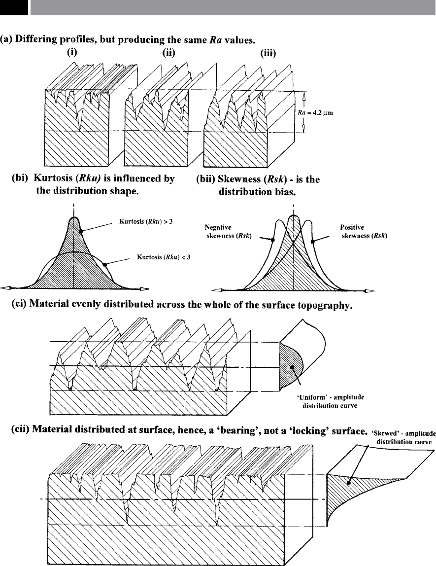
Figure 164. Arithmetic roughness parameter (Ra) can give a misleading representation of the surface topography, so skewness
(Rsk) and kurtosis (Rku) may provide help in the interpretation of the surface. [Courtesy of Taylor Hobson]
.
314 Chapter 7

the surface topography, if used in conjunction with the
Ra value (Fig. 164). is is particularly true for many
machining applications and where a comparison of
‘Manufacturing process envelopes’ is required – more
on this subject shortly. Both skewness and kurtosis can
be mathematically dened, as follows:
•
Skewness parameter (Rsk):
e measure of the symmetry of the prole about the
mean line’. Skewness has the ability to distinguish
between asymmetrical (i.e. having ‘biased tails’) of
identical Ra numerical values (i.e depicted in Fig.
164bii). Skewness can be expressed as follows:
Rsk = �R
q[�lr
l r
�
z
(x)dx]
.
•
Kurtosis parameter (Rku):
Measure of the ‘sharpness’ of the surface prole’. Kur-
tosis can be expressed in the following manner (i.e
shown in Fig. 164bi):
Rku = �R
q[�lr
l r
�
z
(x)dx]
.
Discussing both ‘skewness’ and ‘kurtosis’ in turn, im-
plies that they are separate parameters, but this is not
the case, when one observes Figs. 164bi and bii. How-
ever, to begin with and for ease, each of these param-
eters will be individually mentioned. e Rsk param-
eter cannot distinguish if a prole’s trace has peaks
54
that are relatively evenly distributed above, or below
the mean line (i.e. Fig. 164aiii), or being inuenced
by any isolated peak, or valley (i.e. this topography is
shown to good eect in Fig. 164ai) – within the sam-
pling length.
e Rsk parameter of an amplitude distribution
curve as illustrated in Fig. 164bii, indicates a certain
amount of bias that could be either in an upward, or
downward direction (i.e shown either as: le- and
right-ward, in this example). e amplitude distribu-
tion curve’s contour can be very informative as to the
overall structure of the surface topography. If this curve
is symmetrical in nature then it indicates regularity
of the prole trace (Fig. 164ci), conversely, an asym-
metrical surface’s trace will be indicative of a ‘skewed’
amplitude distribution curve (Fig. 164cii). Utilising
54 ‘Peaks’ , are oen known by a variety names, such as ‘spikes’ ,
or to use a more scientic term this would be: ‘asperities’.
the skewness parameter distinguishes between prole
traces having if not similar, or identical Ra values.
Machined surfaces can exhibit a broad range of
surface topography-related conditions. For example,
a boring operation with a relatively long length-to-di-
amter ratio may result in bar deection (i.e. elastic de-
formation) and occasion the cutting insert to deect,
producing large peak-to-valley undulations along the
bore (waviness). Super-imposed onto these longer
wavelengths are small-amplitude cyclical peaks – peri-
odic oscillations, indicating vibrations resulting from
the boring process. us, the consequential surface
prole for the bored hole, would portray the interac-
tions from the boring bar deformations and any har-
monic oscillations. e likely outcome of such a bor-
ing operation and the bar’s relative motion, would be
reected in the prole trace, exhibiting a low average
prole height, but with a large range of height values.
Moreover, a highly negative skewness is indicative of a
good bearing surface, particularly if some valleys are
present to allow for subsequent oil-retaining abilities
(Fig. 164cii).
e shape of the amplitude distribution curve in
terms of its relative ‘atness’ , or ‘spikeness’ can also
relay useful information concerning the ‘dispersion’ ,
or ‘randomness’ of the surface prole, which can be
quantied by means of the surface descriptor known
as kurtosis (Rku). However, unlike skewness (Rsk),
kurtosis can detect if the prole peaks are distributed
in an even manner across the sampling length’s trace
(Fig. 164ci), or vice-versa. is latter case of producing
both a ‘spiky’ and ‘skewed’ distribution having either
a positive, or negative skew to its resultant distribu-
tion with its associated surface topography – is shown
in Fig. 164cii. As a consequence of this ability to dif-
ferentiate the variations of the actual surface topog-
raphy, Rku is a benecial parameter in the prediction
of in-service component performance, with particular
respect to any potential lubrication-retention issues,
or for any succeeding industrial wear behaviour cir-
cumstances.
Material Ratio Curve (Rmr)
e material ratio curve (Rmr) represents the prole as
a function of level. Specically, by plotting the bearing
ratio at a range of depths for the prole, the manner by
which the bearing ratio changes with depth, provides
a method of characterising dierent shapes present on
the prole (i.e. see Fig. 165). e bearing area fraction
Machinability and Surface Integrity 315
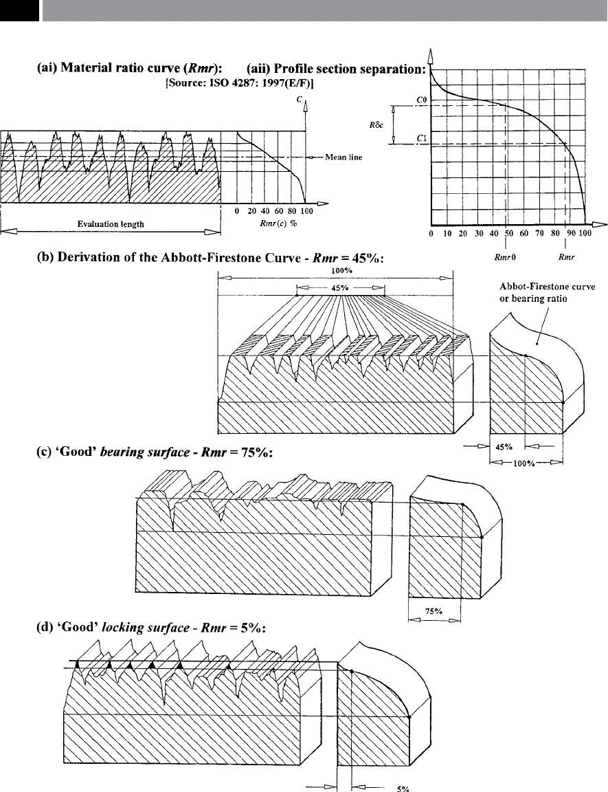
Figure 165. Hybrid surface texture parameters – spacing and depth. [Courtesy of Taylor Hobson].
316 Chapter 7

can be dened as: ‘e sum of the lengths of individual
plateaux at a particular height, normalised by the total
assessment length’ – with this parameter designated by
Rmr (Fig. 165ai and aii).
In the majority of circumstances mating surfaces
demand specic ‘
tribological conditions’
55
: these are
the direct result of particular machining operational
sequences. Normally, the initial production opera-
tion will establish the general shape of the machined
surface – by ‘roughing-out’ – providing a somewhat
coarse nish, with subsequent operations to improve
and enhance the nish, resulting in the desired de-
sign properties. is machining strategy provides the
operational sequence that will invariably remove sur-
face peaks from the original machining process, but
oen leaves any deep valleys intact. is standardised
industrial machining practice of ‘roughing and n-
i
shing’ , produces a type of surface texture known as
a ‘stratied surface’. When these ‘stratied surfaces’
occur, the height distributions tend to be negatively
skewed making it somewhat dicult for an ‘averaging
parameter’ like Ra to represent the surface eectively
to the designer’s specication, or in matters concern-
ing quality control.
In the diagrammatic representation for the deriva-
tion of the Abbott-Firestone curve
56
, or ‘Material ratio
curve’ (Rmr) shown in Fig. 165b, this enables the user
to select diering slices, or depths through the prole,
with these ‘slices’ having a specic ratio for the pro-
portions of air-to-material. e top of the highest peak
within the prole trace having been evaluated, estab-
lishes the reference, or zero percentage line for the Rmr
curve. Calculation of this curve is inuenced by the
largest peak’s height in relation to the others, although
in reality, the eect of a single peak on a surface’s in-
55 ‘Tribology’ , was a technology that originated about 40 years
ago, its name was derived from the Greek ‘τριβοσ’ translated:
‘Tribos’ – meaning ‘rubbing’ so that the literal translation
would be the ‘science of rubbing’. Today, tribology can be more
accurately dened as: ‘e science and technology of interacting
surfaces in relative motion and of related subjects and practices’
(Williams, 1996, et al.).
56 ‘Abbott-Firestone curve’ ,
was named aer two researchers
in the USA working in the early days of surface topography
– circa 1933. ey dened the ‘Bearing area fraction’ at a
given height above the mean line as: ‘e proportional length
of all plateaux which would result if the surface were abraded
away, down to a level plane at that height’ (omas, et al.,
1999).
service function has little signicance. In order to mi-
nimise the eect of a single peak on the Rmr curve,
an articially-induced reference line is chosen to shi
this line below the highest peak – as illustrated in Fig.
165b – this value now being expressed as a material
ratio percentage (i.e. in this example the Rmr being at
45%). Specifying for example, an Rmr at the 5% refer-
ence line (Fig. 165d), testies that the top 5% of the
prole is not included as part of the calculation for the
‘material ratio’. e selection of the zero line beneath
the highest measureable peak will be dependent on the
topography of the associated peaks in the prole trace,
but industrial practice suggests the reference level is
usually set between 2% to 5%.
7.5.2 Machined Surface Topography
Tool nose insert geometry (Fig. 166a) plays a impor-
tant role in the resultant machined surface topography
of a turned component’s surface. Longitudinal turn-
ing operations will leave the residual eects of this
partial tool nose geometry on the workpiece surface
as ‘machined cusps’ forming the dominant prole on
the turned surface topography (Figs. 166b and 169).
is geometry is a complex relationship of curved and
linear inter-connected portions whose insert prole is
‘fashioned’ onto the turned surface – being apprecia-
bly inuenced by the pre-selected feedrate (Fig. 166a).
erefore, according to the ‘Shaw-model’ (1984, et
al.) – being a somewhat ‘simplied geometry’ with-
out chip-breakers present, with an enlarged view of
the turning insert’s nose region (Fig. 166a and b), its
resultant surface topography can be dened by three
distinct insert-related factors, these are:
1. Nose radius – r = O
T (i.e. illustrated in Fig. 166b),
2. End-cutting edge angle – denoted by C
e
(i.e. shown
in Fig. 166a),
3. S
ide-cutting angle – denoted by C
s
(Fig. 166a).
In eect, there are three discrete ‘turning-cases: I, II
and III,’ that may occur when utilising the tool nose
cutting insert geometry shown (Fig. 166a), when com-
puting the theoretical peak-to-valley (R
th
) surface tex-
ture. When a very light D
OC
and its associated feedrate
is imparted onto the workpiece’s surface, then ‘C
ase I’
conditions will be met – illustrated by the high-den-
sity cross-hatched portion of the insert‘s geometry de-
picted in Fig. 166a. e mathematics of the theoretical
cusp height (R
th
) in Fig. 166b, is given by the following
expression:
Machinability and Surface Integrity 317
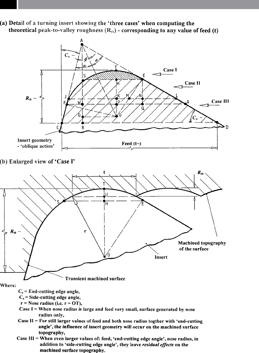
Figure 166. How the ‘residual inuence’ of the turning insert’s partial geometry combined with feedrate, aect
the subsequent machined component surface topography
.
318 Chapter 7

R
th
= OT – OU
= r – (r
2
– t
2
/4)
½
∴R
th
≅ t
2/
8r Case I
When medium values of the turned feedrate are
utilised – as is the situation in ‘Case II’ (Fig. 166a),
then both the tool nose (r) and the partial eect of
the ‘End-cutting angle’ (C
e
) must be considered, when
estimating the deeper ‘R
th
’ value. Assuming that ‘t’ is
equal to ‘JL’ (Fig. 166a and b), then the following geo-
metrical conditions are met:
t = JK+HE+NL (Fig. 166a)
∴ t = [r
2
– (r – R
th
)
2
]
½
+ r sinC
e
+
r(R
th
/r – 1 + cosC
e
)cotC
e
Case II
NB is equation is valid, just as long as the ‘t’ length
lies between positions: ‘SE’ and ‘FR’.
If even larger values of ‘t’ are utilised (i.e. higher feed-
rates), then the three geometrically curved and linear
portion’s of the cutting insert’s prole, will aect resul-
tant turned surface topography. Namely, this surface
topography aer machining, will now be comprised of
the sum of the portions of the: end-cutting angle ‘C
e
’;
nose radius ‘r’; together with the side-cutting angle
‘C
s
’ , as follows:
R
th
= AB – AG + r (Figs 166a and b)
� R
th
=
t
tan C
s
+cot C
e
−
r cos(−C
e
�−C
s
�)
sin(−C
e
�+C
s
�)
+ r
Case III
e equations given in ‘Cases: I, II and III’ , can be
utilised to produce a ‘non-dimensional’ graphical plot
for various cutting insert approach angles (i.e. see
Shaw, 1984 – p 513) enabling the estimated value of
‘R
th
’ to be found – for any combination of: ‘t’; ‘r’; ‘C
e
’;
plus ‘C
s
’.
Historically, it has been well-known that there exists
a ‘minimum undeformed chip thickness’
57
and if a value
57 ‘Minimum undeformed chip thickness’* was proposed some
years ago by Sokolowski (1955), where it was suggested that
a ‘limiting value’ occurred for a chip thickness, below which a
tool simply rubs.
*In the experiments undertaken at the time by Sokolowski,
using a very sharp and honed single-point turning tool with
a cutting edge nose radius of 12 µm at a cutting speed of
210 m min
–1
, the smallest cut that could be taken had a depth
of 4 µm. For additional information on succeeding research
work on this sbject, also see Footnote 58.
is smaller than this actual chip-thickness, it is not pos-
sible to form a successful chip, as a result, only rubbing
will occur – this being a combination of many inter-
related factors. Applying this ‘minimum undeformed
chip thickness’ concept to the insert’s secondary cutting
edge, it was found that a small triangular portion of
workpiece material which should have been removed,
is normally le ‘in-situ’ (Fig. 167). is fraction of the
workpiece le behind, has been the subject of intensive
interest by previous machinability researchers over a
number of years and is known as the ‘Spanzipfel’
58
. In
Fig. 167b, the raised portion (i.e. Spanzipfel) occurs at
increments equivalent to that of the feed rev
–1
and is il-
lustrated in Fig. 167a. An expression has been derived
to take account of this Spanzipfel on the theoretical
surface texture, as follows:
R′
th
= t
2
/8r + t
m
/2 (1+ rt
m
/2)
NB In this equation, the 2
nd
term represents the con-
tribution of the Spanzipfel.
Both the theoretical values for the surface texture and
actual ones from the trials are in close agreement,
which was not expected, as the Spanzipfel will be sub-
ject to some plastic deformation – as it comes into di-
rect contact with the tool’s clearance face.
In both end- and face-milling operations (Fig.
168a), the machining process is one of interrupted
cutting, tending to impart an isotropic surface topog-
raphy to the milled surface (Fig. 168b). If in Fig. 168b
(i.e. top diagram) the excess stock material is removed
by face-milling, the resultant surface exhibits quite
a complex surface topography. is milled surface
complexity results from the cutter’s trailing edge, as it
moves over the previously cut surface at the periodic
and pre-selected feedrate. is periodic surface topog-
58 ‘Spanzipfel’ , was initially investigated and analysed by Bram-
mertz (1960). He was particularly interested in the Spanzip-
fel’s aect of the resulting machined surface topography/tex-
ture. Later work by Pahlitzsch and Semmler (i.e. between 1960
to 1962), looked at the ‘minimum undeformed chip thickness’
and the Spanzipfel’s inuence when ne-turning AISI 1045
steel workpieces with specially-sharpened ceramic tooling.
Here, they found that machining with this much more abra-
sive-resistant ceramic tooling, the ‘minimum undeformed chip
thickness’ height could be dramatically-reduced to just 1 µm.
Cutting speed utilised in these tests was 400 m min
–1
and the
machinability trials used an in-cut time of just 6 seconds – in
order to maintain a sharp cutting edge on the tools.
Machinability and Surface Integrity 319
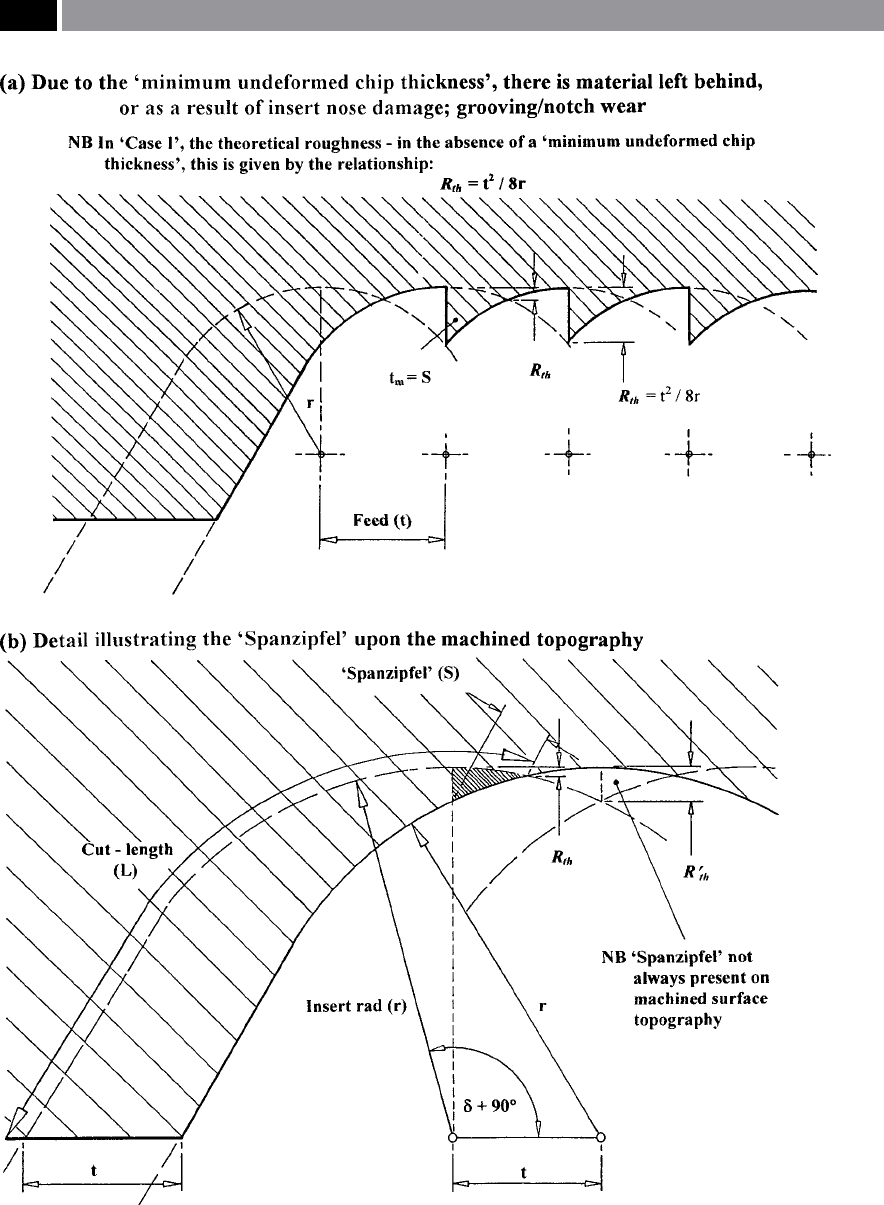
Figure 167. The aect of the ‘minimum undeformed chip thickness’ on the machine topography, producing the so-
called ‘Spanzipfel eect’
.
320 Chapter 7

raphy will not occur, if either a ‘slight’ milling spindle
camber is utilised (i.e. see Fig. 86), or some form of
‘torque-controlled machining’ (TCM) system is em-
ployed, that usually incorporates some form of ‘adap-
tive control constraint’ (ACC) engagement of the feed-
ing-system – additional information on the subject of
TCM will be given in the nal chapter. e major rea-
son for TCM feeding variability, is because the torque
is monitored and as the stock height varies along the
workpiece’s length, the torque is either lessened by
slowing the feedrate, or increased, thereby maintain-
ing relatively constant cutting forces on the tooling.
is form of ‘adaptive control’ (ACC) by constraining
the cutter’s feed, will impart a variable surface topog-
raphy to the milled surface.
In the previous milling scenario where there was
no necessity for an TCM requirement, the milling
cutter’s rotation in combination with the feed for a
given ‘cut-o’ slightly changes the milled surface to-
pography. It introduces some variability to the respec-
tive cusp heights along the workpiece’s milled surface
(Fig. 168b). Here, the periodic nature of the surface
topography is regular (i.e. a constant ‘Sm’), but its pe-
riodicity marginally changes according to whether the
surface is measured at the centre of the cut, or oset
across the face-milled surface, which has an some ef-
fect on the relative cusp heights. Conversely, across the
milled surface at arbitrary positions denoted in these
examples as: ‘X-X’ and ‘Y-Y’ (Fig. 168b), the topog-
raphy uctuates somewhat at a predetermined and
quantiable interval, depending upon where the sur-
face trace was taken. Hence, any milled surfaces with a
non-directional, or indenable Lay – as is the case for
most re-cutting eects introduced by either end-, or
face-milling operations, should not simply have an ar-
bitrary Ra quoted on the engineering drawing, as this
has been shown (Fig. 168b) to be somewhat meaning-
less. Milled surfaces having these latter characteristics,
requiring the need to indicate the maximum tolerable
Ra value for a given Lay direction – in a similar fash-
ion to that of an anisotropic machined surface topog-
raphy.
Returning to the longitudinal turned surface to-
pography once more. If consideration is given to the
‘idealised’ turning surface (Fig. 169a and b), then for
a constant tool nose insert geometry and undeformed
chip thickness, as the feed rev
–1
is increased, the sur-
face texture will be degraded. e residual cusps that
periodically occur on the turned surface aer the tool’s
passage along the part, are a product of two previ-
ously described inter-related phenomena (Fig. 154),
namely: the ‘moving-step eect’; in conjunction with
the ‘emerging diameter’. is relationship diminishes
the notable height of the turned cusps with a reduced
feed rev
–1
, while it increases with larger feed rev
–1
– this
aspect being depicted in Figs. 169a and b, respectively.
If a proportionally larger feed rev
–1
is selected, this in-
creases the residual inuence of the tool nose contact
region on the surface – as formerly mentioned when
discussing Fig. 166. As a result of higher feeds the
RSm increases, which inevitably heightens the cusps,
promoting a larger recorded value in Ra, in associa-
tion with greater angles for ∆q (Fig. 169b). Of course,
the opposite is true in the case of reduced feeds (Fig.
169a). Explicitly, as a smaller tool nose contact region
occurs – with reduced feed rev
–1
(i.e ‘Case I’ in Fig.
166a), this has the eect of producing a smaller cusp
height (R
th
) and its accompanying Ra, giving a more
shallow value of ∆q; due to the partial curvature of the
tool nose radius tending toward zero as it approaches
tangency with that of the workpiece’s axis (Fig. 169a).
e dominant factor here is the feedrate, as it has an
enormous inuence on the resultant turned cusps, af-
fecting their: height; prole shape; periodicity; in asso-
ciation with the pre-selected tooling geometry; these
factors radically inuencing both the measurement
and magnitude of the machined surface topography,
which in turn, aects the surface texture parameters. If
just the Ra parameter had been specied, it could not
adequately describe the nature and condition of the
surface topography in any consequential manner.
Assuming that standardised cutting conditions
are selected for a turning operation: workpiece com-
position; rotational speed; feedrate, undeformed chip
thickness, with only the tool nose geometry change,
then the resulting surface topography will be markedly
dierent. is divergence in machined topography is
illustrated to good eect in Figs. 169c and d, where
turned ferrous P/M compacts are depicted. Here, two
extremes of cutting insert nose radii are utilised: Fig.
1
69c the nose radius was 0.8 mm; whereas in Fig. 169d
a button-style insert (φ1
2 mm) having the equivalent
of 6 mm nose radius was used. e turning insert with
the 0.8 mm nose radius produced visually-apparent
regularly-spaced cusps and despite the fact that a new
turning insert was employed, there is evident signs of
tears, laps and burrs present around the turned pe-
riphery. In contrast in Fig. 169d, the turned surface
topography appears appreciably smooother in prole,
although even here, the surface topography is marred
by similar tears, etc., which might be a cause for its
potential rejection. is smoother surface was due to
Machinability and Surface Integrity 321