Smith G.T. Cutting Tool Technology: Industrial Handbook
Подождите немного. Документ загружается.


costs can be calculated, for a simple turning operation:
the method can be modied for machining centres
and for most other machining operations.
As can be seen from Table 12, the cutting s[peed
has a major impact on the value of ‘CT’ , because an
increase in cutting speed normally results in faster
tool wear rates, with the tool charge per component
increasing as a result. Tool costs today, now account
for only a small proportion of the total costs of pro-
duction, owing to the fact that the latest tooling can
operate at higher feeds and speeds than their earlier
counterparts. When the tool costs actually rise – due
to greater wear rates as a result of increased cutting
speeds, it naturally follows that associated tool perfor-
mance will also increase.
For any machining operation there exists an ‘eco-
nomical tool-life’ (T
e
), which can be calculated from
the following formula:
T
e
= (
α
− )(
C
T
C
m
+ t
C
)
Economical tool life
Where:
T
e
= Economical tool life (minutes),
α = Slope of the V-T curve (i.e. measured from
graph),
C
T
= Cutting tool cost per edge (i.e. obtained as de-
scribed above),
C
m
= Machine tool, labour, and related overhead costs
– charged per minute,
t
C
= Tool-changing time per minute for operation in
question*.
*is tool-changing time will vary depending upon
whether the chosen cutters are of the ‘conventional‘, or
‘modular quick-change’ tooling varieties.
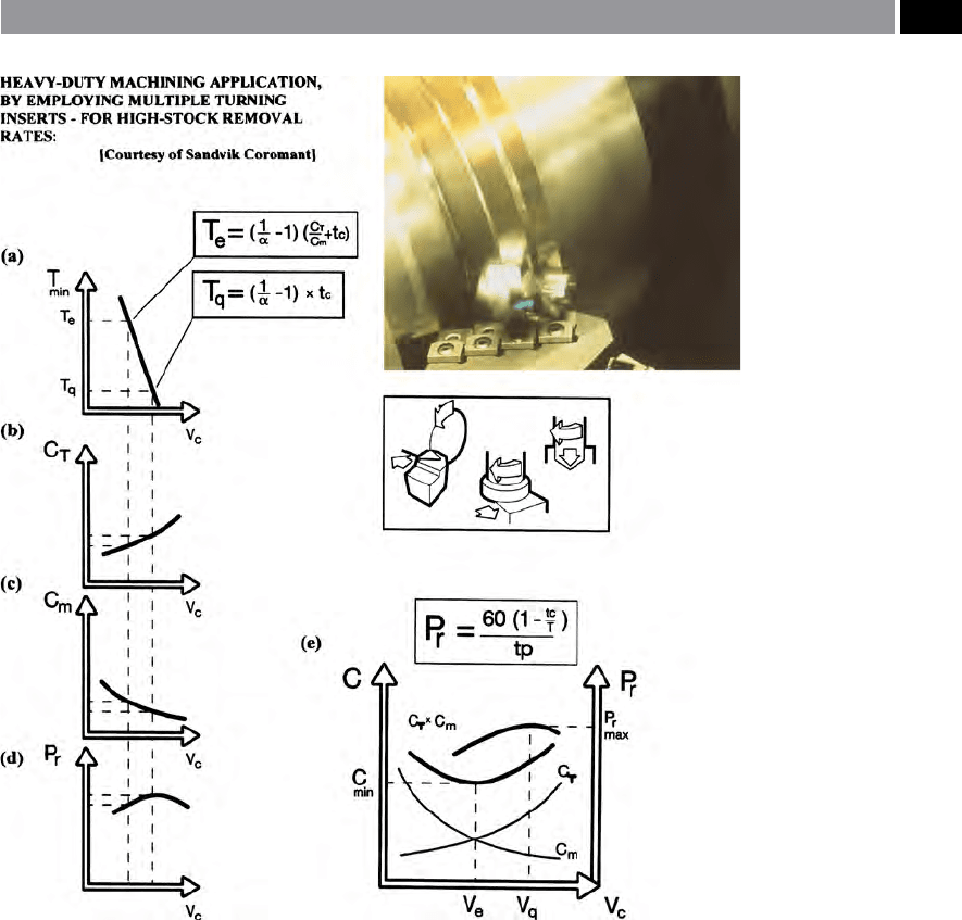
In Fig. 177a, the tool-life at ‘maximum production rate’
(T
q
) is shown, which is a variation of the calculation
given above for ‘economical tool life’ (T
e
), where the
variables are identical, but in the former case a higher
cutting speed is employed, resulting in shorter tool-
life. Even though the lowest possible machining cost
per component can be calculated with the most eco-
nomical cutting speed, it is oen desirable to utilise
a faster machining strategy. is increased speed, will
involve supplementary costs, although it can only be
warranted if higher production output results. If the
number of components per hour (P
r
) is plotted (Fig.
177d) in relation to the cutting speed (V
c
), a repre-
sentative curve will result. is curve is redrawn and
shown in Fig. 177e, this now being a ‘composite’ of the
sum of the: machine/labour/overhead costs (Cm); with
tooling cost (CT). e zenith of this curve (Fig. 177e),
represents the highest production rate (P
r
max). While
the cutting speed (V
q
) is associated with the peak of
the curve, which is greater than the most economical
rate (V
e
), with the values between these two points,
representing the ‘high-eciency range’ for a particular
operation.
In Fig. 177e, the additional vertical axis depicted,
represents the production rate (P
r
) – this being the
number of components machined per hour, it can be
calculated in the following manner:
P
r
= 60 (1 – t
C/
T)/tp
Where:
t
C
= Tool-changing time per minute for operation,
T = Tool life,
tp = Total time per component (i.e. including: ma-
chining, handling and down-tome).
e relationships mentioned above represent theoreti-
cal associations. So, some caution should be applied
when using these factors and they need to be treated
as a ‘starting-point’ only for both the values and trends
represented here. Moreover, they are subject to vari-
ability, due to the complex relationships and interac-
tions found during machining operations.
7.7.3 Return on the Investment (ROI)
As an alternative approach to the above mentioned
cutting tool costs and production output interactions,
is to relate any productivity improvements to both the
actual machinery cost and the total invested capital
– to achieve this level of manufacturing yield. In the
previously described machinability tests, the work
seldom considers rates of production, or relates the
ndings to actual increases in the total economics of
production.
A signicant scal argument is that any gures
obtained from such testing, should highlight the ‘im-
proved’ ROI, which can be obtained by any manu-
facturing company utilising the latest tooling, in
conjunction with the application of ecient cutting
conditions.
e following simple formula can be utilised to cal-
culate the ROI for a particular: production operation;
machine tool; machining cell; etc.:
342 Chapter 7
ROI = (T
S
)(M
C
)/(MT
I
)
Where:
T
S
= Time savings per year (i.e. in hours),
M
C
= Machine tool charge (per hour),
MT
I
= Machine tool investment.
In this section, only a supercial treatment has been
given to the economic argument relating associated
capital equipment costs and their overheads, to out-
put productivity. More intricate and sophisticated eco-
nomic models can be obtained in the literature.
7.8 Cutting Force
Dynamometry
Introduction
During machining operations, plastic deformation,
friction between the tool and workpiece, together with
micro-fractures and -ssures occur. ese mechanical
phenomena produce measurable cutting and forming
forces with very high-frequency acoustic emissions
(AE). e application of AE in association with other
Figure 177. The correlation of typical manufacturing cost factors: machining costs, together with
their resultant productivity. [Courtesy of Sandvik Coromant]
.
Machinability and Surface Integrity 343

sensors, such as: force transducers, accelerometers can
be coupled to neural networks to give a psuedo-form
of articial intelligence (AI) – more will said relating to
cutting tool monitoring and analysis in a succeeding
chapter. Many of the early attempts at cutting force
monitoring were by using several strategically-placed
resistance-type of strain-gauged mechanical elements.
ese strain-elements were designed so that at a par-
ticlur portion of their geometry they could either
minutely: buckle, bulge, or twist – well within their
elastic limit. At the positions of greatest sensitivity
on these mechanical elements, strain-gauges were se-
curely placed and wired into a ‘Wheatstone bridge re-
si
stance circuit’
71
, which as the gauges distorted they
changed their micro-resistance, which could then be
fed through suitable instrumentation. ese strain-
gauged elements could be calibrated against ‘known’
mechanical devices (e.g. ‘proving-rings’
72
, or similar),
71 ‘Wheatstone bridge resistance circuits’ – invented by Sir
Charles Wheatstone: circa 19
th
Century, for accurately
measuring resistance in an electrical circuit. Simply, a ‘bridge
circuit’ consists of: four resistances; a galvanometer; with a d.c.
power supply. In essence, in these highly sensitive resistance
‘bridges’ they are used to detect minute changes in strain gauge
resistance. A typical ‘full-bridge’ consists of the four resistors:
‘R
1
’; ‘R
2
’; ‘R
3
’; ‘R
4
’; suitably coupled to the galvanometer and
d.c. supply. Typically, the most simple strain-gauged circuit
would consist of: a resistance ‘R
1
’ which here for argument,
is the gauge used for strain measurement. Resistance ‘R
4
’ is
a second strain gauge which here, could remain at constant
resistance. e other ‘half of the bridge’ , resistances ‘R
2
’ and
‘R
3
’ are variable resistors which by adjustment, are utilised to
‘balance’ and ‘rebalance’ the bridge (i.e employed to reduce
the current across the galvanometer arm to zero). erefore,
when the ‘bridge’ is ‘balanced’ , the ratio of the gauges and the
variable resistances are equal, thus:
R
1/
R
4
= R
2
/R
3
∴ R
1
= R
4
× R
2
/R
3
(Collet and Hope et al., 1974)
72 ‘Proving-rings’ ,
are laboratory calibrated and certicated me-
chanical device, normally consisting of: a steel ring; dial gauge
and loading pads. It is usually employed in the calibration of
force-measuring systems – only within its maximum permis-
sible load. Such ‘proving-rings’ can be manufactured for either
high sensitivity – for strain-gauge applications, or for more
robustness – when calibrating tensile testing machines. In
practice, the steel ring if compressed, allows the diameter to
minutely contract in direct proportion to the applied force,
with its deection accurately measured by a dial gauge located
across the centre of the internal portion of the proving-ring’s
diameter. Changes in the dial gauge readings, can be converted
to force measurement by means of a suitable calibration graph,
or more simply, by multiplying the gradient of the graph – as
the graph produced has a straight-line relationship. (Ramsey
et al., 1981)
allowing the resolved cutting forces during subsequent
machining to be data-logged, for suitable in-depth
analysis by the user. Strain gauge dynamometers based
upon the Shaw and Cook (1954) model, normally re-
quire several design criteria to be addressed, if they are
to perform satisfactorily, these factors are:
1
. at the dynamometer should have a sensitivity of
1% of its mean designed force,
2
. Such a dynamometer requires a natural frequency
of at least 4 times the ‘forcing frequency’ ,
3. e strain-gauged circuit elements should produce
the minimum of cross-coupling (i.e. ‘cross-talk’ is
<2%) – when calibrated.
NB
is latter point, can be assessed by a range
of calibrated ‘proving rings’ , or ‘torque arms’ – if
required to measure torque eects in the circuit,
thegraphical calibration should indicate: both plot-
ted linearity and also be coupled to minimal hys-
teresis
73
.
Today, most multi-axes cutting force dynamometers
utilise sensing elements, based upon the piezoelectric
eect
74
and these ‘active sensors’ , will now be more
fully discussed.
Piezoelectric Dynamometers
ese high-rigidity force transducers provide an elec-
trical output signal under the eect of direct element
deformation. Hence, element deformation can be kept
several degrees of magnitude smaller than that of the
‘passive systems’ – such as those utilising strain-gauged
elements. With most ‘dynamic systems’ such as those
employing quatrz-based elements, their inherent de-
gree of rigidity and a broad measuring frequency
range creates smaller measurement interference and
73 ‘Hysteresis loop’ is an area bound between the loading and
unloading paths (i.e. typically found in a stress-strain curve),
indicating energy dissipation, or damping.
74 ‘Piezoelectric eect’ ,
was discovered by Pierre and Jacques
Curie in 1880. A piezoelectric material (e.g. quartz, or Ro-
chelle salt) is a special kind of insulator which, if compressed
along one of its axis, acquires an electrostatic charge on the
material’s opposite faces. Hence, when such material is ac-
curately and precisely cut to the desired shape, it acts as a
piezoelectric transducer, hence its input is force and its output
is charge. ese piezoelectric elements, can be suitably posi-
tioned and arranged and thus, used in dynamometers for dy-
namic cutting force measurement.
344 Chapter 7

as a result, oer extremely fast process response, in
comparison to those of the of the ‘non-rigid type’
– having long measurement paths (i.e. found in con-
ventional strain-gauged elements). Unlike ‘passive sys-
tems’ utilising strain-gauges, it is virtually impossible
to perform static measurements by using piezoelectric
transducers, even though an electric charge delivered
under static load can be registered, it cannot be stored
for any realistic time period
75
.
e design of most of today’s multi-component
dynamometers use piezoelectric elements which are
quintessentially comprised of a stack of quartz discs,
or plates with accompanying electrodes being installed
i
nto a stainless steel housing (Fig. 178ai and aii). Every
disk, or plate has been precisely cut in a denite crys-
tal axis, with their sensing orientation coinciding with
that of the axes of the force components t
o be measured
(Fig. 178). In practice, the electrodes can collect the
‘charge’ on their respective quartz disk’s surfaces, these
being suitably ‘hard-wired’ to their appropriate and
corresponding plug connectors. As shear forces can
only be transferred by frictional contact, a certain
minimum of friction is essential between the quartz
disks, electrodes and housing. Depending upon the
shear force magnitude (i.e. measured) a more-or-less
high pre-loading of the system must be generated by
a pre-loaded bolt. is act of preloading the system is
absolutely essential and is usually undertaken when
the force transducer is initially installed into the dyna-
momoter by the manufacturer.
A typical three-component dynamometer (Fig.
178ai), consists of sensors with two shear quartz pairs
– namely for ‘F
X
’ and ‘F
Y
’ , plus one pressure quartz pair
– for ‘F
Z
’ , assembled in a suitable housing. Each quartz
pair has two identical plates stacked with a common
75 ‘Piezoelectric storage’ – for static loading, this cannot be
achieved because an insulating material would have to have
innitely high resistance, together with ampliers that are
perfectly free from any form of leakage and ‘non-operate cur-
rents’ , with an amplication factor of innity! e dri in
today’s charge ampliers is below ±0.03 pC s
–1
. In static mea-
surements performed with ‘load washers’ , this means that in
practice, the zero-shi is limited to within ±10 mN s
–1
. For
example, if a static load of 10 kN is measured for one min-
ute, then aer this time, the result of the measurement can
only be invalidated by a maximum ±0.6 N, that is by ±0.006%.
Hence, it is a simple task to piezoelectrically measure large
forces for minutes, or hours, but small forces can only be mea-
sured ‘statically’ for very short time-periods. us, piezoelec-
tric transducers are normally referred to as being: ‘quasistatic
measurement elements’.
electrode between them, oering twice the sensitivity.
is three-component dynamometer is constructed
with four of these three-component sensors mounted
in parallel between the base and top plate, being as-
sembled with a high preload. Given that the outputs
from the four sensors are in the form of an electrical
charge, they are able to be interconnected within the
dynamometer body. With this particular sensor ar-
rangement, it is possible to obtain up to eight charge
outputs from the dynamometer.
e four-component dynamometer shown in Fig.
178aii, has several shear quartz plates arranged in a cir-
cle (i.e. top circular element), with their sensitive axes
being tangential, allowing an element to be formed
responding to a moment ‘M
Z
’. In this dynamometer,
the four-component sensor is obtained by assembling
this element (i.e. ‘M
Z
’) in a housing, together with two
shear quartz pairs – for ‘F
X
’ and ‘F
Y
’ , plus one pressure
quartz element pair for ‘F
Z
’. So, by mounting this sen-
sor assembly under a high preload between the base
and the top plate, it results in a four-component dy-
namometer, capable of simultaneous measurement of:
‘F
X
’ , ‘F
Y
’ , ‘F
Z
’ and ‘M
Z
’.
For both accurate and precise machinability and
data-gathering assessment, these invaluable piezoelec-
tric dynamometers oer the following advantages and
typical properties:
•
High rigidity (‘c
x
’ , ‘c
y
’: >1 kN µm
–1
, ‘c
z
’: >2 kN µm
–1
),
hence producing a high natural frequency (‘f
o
’: ≈3.5
kHz),
•
Wide measuring range (-5 to 10 kN),
•
Extreme linear sensitivity (‘F
X
’ , ‘F
Y
’: ≈-7.5 pC N
–1
,
‘F
Z
’: ≈–3.7 pC N
–1
) and virtually free from hyster-
esis (≤0.5%FSO),
•
Minimal cross-talk (≤±2%),
•
Environmentally-protected (IP67), typically sealed
against of both cutting uids and debris ingress.
NB S
uch high-quality apparatus is not cheap to
purchase, therefore it should be carefully main-
tained and looked aer, to ensure an extremely long
life and fail-safe operation.
Piezoelectric dynamometers can have their quartz
sensing elements arranged to t into platforms (Fig.
178b), for tment onto a turning machine tools turret
with the cutting tool suitably arranged for turning op-
erations. ese type of dynamometer platforms can be
located on the machine tool’s bed, with the workpiece
clamped onto the dynamometer for milling, drilling,
or grinding operations to be used for specic types of
machinability investigation. In the former case, it is
Machinability and Surface Integrity 345
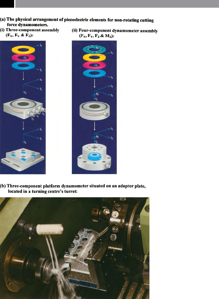
Figure 178. Multi-axis non-rotating dynamometers, used for: milling, drilling and turning
experimental data-gathering and analysis. [Courtesy of Kistler Instrumente AG]
.
346 Chapter 7

not possible to index the turning centre’s turret, due
to the nature of the electrical couplings to the plat-
form, but this problem can be overcome by mounting
a dierent dynamometer conguration, situating the
sensing equipment within the turret – as depicted in
Fig. 179a. Here, the installation of an acoustic emission
sensor (AE)
76
behind the turret in combination with
a multi-component force sensor mounted in the tur-
ret’s pocket – this force equipment having previously
required the necessary of preloading which was pro-
vided by a suitable ‘preload wedge’.
In Fig. 179b, are exhibited the measuring results
from the sensor installation decribed in Fig. 179a – for
a longitudinal (external) turning operation, with the
cutting force components and the AE signals being
simultaneously recorded. e resulting graphs pro-
duced in both Figs. 179bi and bii, show the AE rms
77
and force signals in the case of a tool breakage. e
tool breakage can be readily seen in both signal traces.
Figs. 179biii and biv, show the AE and force sensor sig-
76 Acoustic emission sensors (AE), in metal machining applica-
tions usually capture frequencies in the range of 50 kHz to
>1 MHz in range, this being a usual aid for any form of in-
process monitoring operations. By using a combination of AE
and force monitoring, this has been shown to be a means of
condition monitoring of the cutting tool’s state – more will
be said on this topic later. In metal cutting operations AE oc-
curs due to plasto-mechanical processes of crack formation
and chip removal, in combination with surface friction. Any
form of tool wear alters the contact surfaces between the tool
and workpiece, inuencing and increasing the AE signal in-
tensity. Hence, advanced warning of potential tool breakage
sometimes results in the appearance of micro-ssures in the
tool, which cause an escalation of the AE signals – allowing
a basic form of tool and process monitoring to be achieved.
AE generation in metallic machining operations, can extend
over frequencies of several MHz, although the signal intensity
is normally very low and diminishes with increasing distance
from its source. Any form of machine vibrations and inter-
ferences from the local environment introduce signals from
a low frequency range, meaning that any form of signicant
analysis is normally only possible above 50 kHz. Machine tool
interference sources are usually the result of either electrical,
or hydraulic main and feed drives, as well as from bearing
noise, spindles and gears. ese unwanted interferences can
be suppressed by utilising suitable high-pass lters, or alterna-
tively a well-designed AE sensor(s), with inherent high-pass
frequency characteristics.
77 ‘Root mean square’ (rms), is a measure of the eective mean
current of an alternating current. Its actual rms value is de-
rived from the power dissipation by an ac current.
nals respectively, on the ‘over-turning’ of transversal
holes present in the external turning of the workpiece.
Hence, the interrupted cut can clearly be seen peri-
odically in the resultant force traces. In Fig. 179biii,
the AE rms signal shows this interference, albeit not
very well pronounced, unlike that of the force trace
produced in Fig. 179biv, where a denite noise spike
can be seen. is combination of two complementary
sensing elements and their sensor signals, allows the
reliable detection of a process fault, such as tool break-
age detection.
Until approximately the mid-1990’s, commercial
versions of cutting force monitoring equipment for the
measurement of a rotating cutting tool, or an edge was
not readily available for: drilling, reaming, tapping
and milling applications. A major advantage of these
rotating cutting force dynamometers, is that they can
be used for multi-axes contour milling applications,
or simply for an investigation of a discrete tool’s cut-
ting edge geometry and its anticipated machining per-
formance. An early version of such a rotating cutting
force dynamometer, is depicted in Fig. 180a.
In Fig. 180b, graphs have been produced showing
the cutting force and torque results respectively, pro-
duced by the rotating cutting force dynamometer. In-
terest frequently centres on the forces and moments
acting on the rotating tool. A rotating cutting force
dynamometer (Fig. 180a), allows measurement of
three orthogonal forces: ‘F
X
’ , ‘F
Y
’ , ‘F
Z
’ , together with
the moment ‘M
Z
’. e data measured by the rotating
dynamometer occurs via miniature charge ampliers,
which are then transferred by telemetry to an appro-
priately positioned stationary antenna. e telemetry
involves a bi-directional transmission, with measured
data being transmitted to the ‘stationary side’ of the
monitoring system and any control commands for the
integral charge ampliers transmitted to the appropri-
ate section of the rotating dynamometer. e power
supply to the electronics in the rotor, occurs by the
same antenna, but having a dierent carrier frequency
to that of the data transfer. Typical resultant signals
produced by the rotating dynamometer are shown in
Fig. 180b and have been ‘zoomed’ for the investigation
of a single drill’s cutting edge.
Cutting force dynamometers of various congu-
rations, are invaluable tools for any form of in-depth
machinability study, as they indicate the precise condi-
tions at the cutting tool’s edge(s), in a truly dynamic
situation. All dynamometers that are purchased from
the manufacturer must come with an appropriate cali-
Machinability and Surface Integrity 347
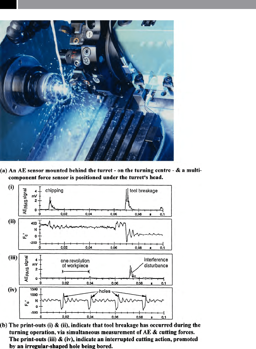
Figure 179. A Rotating Cutting-force Dynamometer (RCD), utilising piezoelectric sensor systems.
[Courtesy of Kistler Instrumente AG]
.
348 Chapter 7
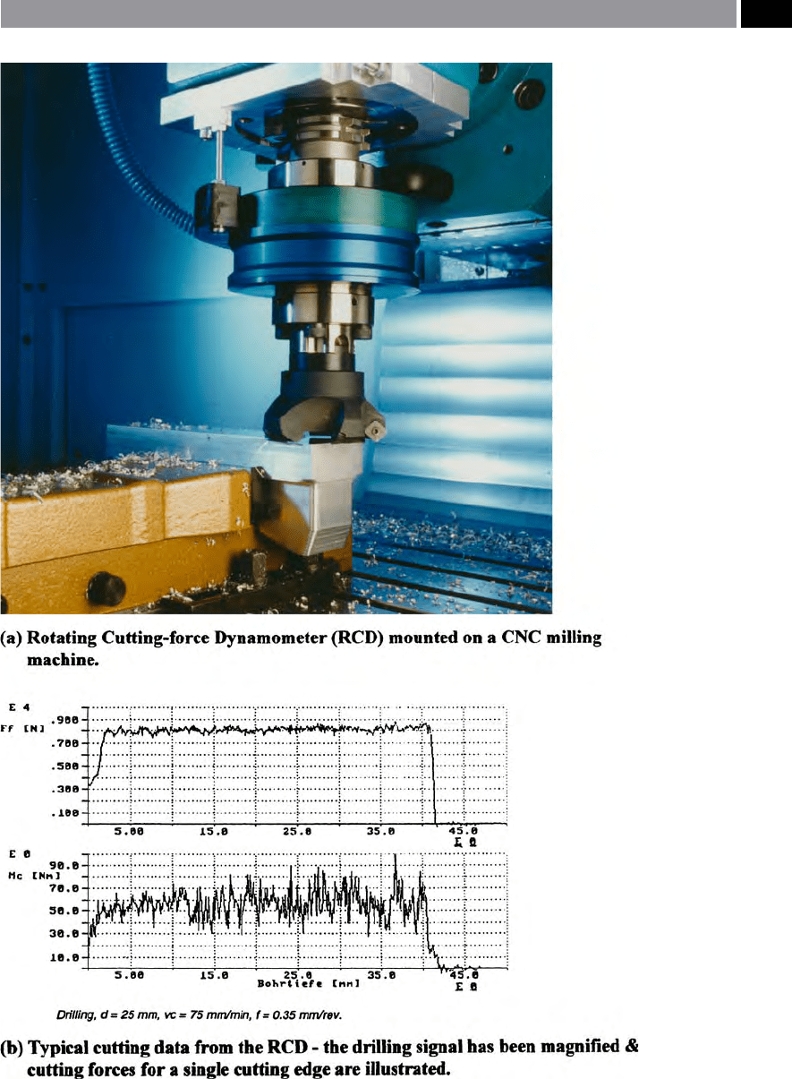
Figure 180. A Rotating Cutting-force Dynamometer (RCD), utilising piezoelectric sensor systems.
[Courtesy of Kistler Instrumente AG]
.
Machinability and Surface Integrity 349

bration certicate, to ensure that the results obtained
are both valid and sound. A cautionary note: if the dy-
namometer has been inadvertently dropped, or it has
possibly collided with an obstruction when in use on
the machine tool, it should be sent back to the manu-
facturer for servicing and recalibration, otherwise,
spurious cutting force data may be the result.
7.9 Machining Modelling
and Simulation
Introduction
Previously, it was been widely accepted that most cut-
ting tool modelling technqiues are somewhat incom-
plete, in both their analysis of the process and their
accompanying derived mathematics. Early, but worthy
attempts at analysing the chip formation mechanics of
the orthogonal cutting process were undertaken ini-
tially by Ernst and Merchant (1941) – shown schemat-
ically depicted in Fig. 181, followed by further work
concerning the analytical graphical interpretation of
the orthogonal cutting action which was presented
by Merchant and Zlatin (1945) and later work by Lee
and Shaer (1951) – not shown. is earlier work
was then followed by Zorev’s (1963) interpretation of
an ‘idealised cutting model’ (Fig. 182). In all of these
above modelling cases and others not mentioned – for
brevity’s sake!, the very complex nature of the cutting
process, is a vast subject ‘straddling’ many engineering
and physical disciplines. Such modelling involves as-
pects of: the tool’s geometry, chip/tool contact lengths
and pressures, chip formation, cutting forces, fric-
tional and thermal factors and so on, making it vir-
tually impossible to obtain close agreement between
with any truly meaningful results between each pro-
posed model. is lack of correlation of these model-
ling processes, is to be expected, as in reality a shear
zone, rather than a shear plane exists, but for mathe-
matical treatment, a shear plane allows some degree of
geometrical association. Due to the complex nature of
the inter-related variables that occur in any dynamic
cutting situation for just simply the orthogonal cutting
process, let alone for oblique machining modelling,
this has meant that the ‘optimum modelling solution’
has as of now, not yet been fully addressed.
Many ‘learned tomes’ have been written in the past,
concerning the ‘mechanics of machining’ and it is not
the intention to fully discuss them here, in this book
which is principally concerned with ‘current practice’
concerning machining applications. However, a brief
resumé of just one of these ‘orthogonal models’ shown
in Fig. 181 will be mentioned below, together with a
concise review of friction in metal cutting operations
(Fig. 182) will be presented, to attempt to show why
the subject of ‘theoretically modelling’ the cutting pro-
cess is so complicated.
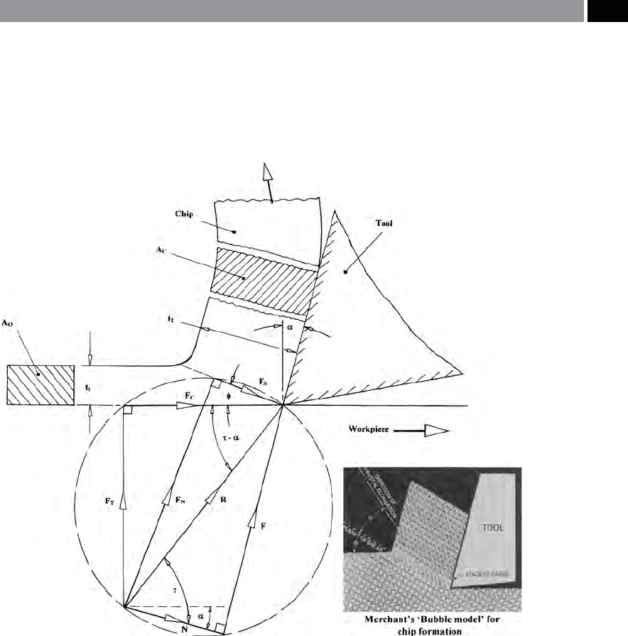
Ernst and Merchant’sComposite Cutting Force Circle
If a continuous chip formation is produced when ma-
chining ductile materials in an orthogonal cutting
process, such as that found when cylindrically turn-
ing a component’s periphery with an undeformed chip
thickness (‘t
1
’), this will cause a chip compression (‘t
2
’)
– Fig. 181(top). e cutting forces can be obtained by
employing a cutting force dynamometer as discussed
in the previous section, to typically measure the forces
‘F
C
’ and ‘F
T
’ and so on. By utilising such cutting tool
dynamometry, Ernst and Merchant (1941) were able
to classify the forces acting in the vicinity of metal cut-
ting which gave rise to both local plastic deformation
and frictional eects. In Ernst and Merchant’s theory
which is oen termed the so-called ‘shear-angle solu-
tion’ ,
it is assumed that the cutting edge is always per-
fectly sharp and that a continuous-type chip without
BUE occurs, this former assumption in practice does
not actually occur. Moreover, another assumption in
their analysis it was that the chip would behave like
a
‘rigid body’ , which is held in equilibrium by the ac-
tion of the applied forces transmitted across the tool/
chip interface and transversely over the shear plane.
Boothroyd (1975), oered a reasonably ‘elegant solu-
tion’ to Ernst and Merchant’s numerical and geometri-
cal analysis and, this has been somewhat modied and
further simplied below. In order to abridge the ‘shear-
angle solution model’ shown in Fig. 181, the resultant
force ‘R’ is depicted acting at the tool’s cutting edge,
being resolved into components ‘N’ and ‘F’ in direc-
tions along and normal to the tool’s face respectively,
as well as into components ‘F
N
’ and ‘F
S
’ – once again,
along and normal to the shear plane correspondingly.
Further, the cutting force ‘F
C
’ and the thrust ‘F
T
’ com-
ponents of the resultant force, are also shown. Here, it
can also be assumed that the entire resultant force is
transmitted across the tool/chip interface and that on
both the tool’s ank and edge no force occurs, mean-
ing that a zero ‘ploughing-force’ is present – see Fig.
184 which illustrated this ‘nose-rounding eect’.
350 Chapter 7
e foundation purported by Ernst and Merchant’s
theory, was the proposition that the shear angle ‘φ’
would acquire such a value, thereby reducing the ac-
tual work done to a minimum. In view of the fact that
that for preselected cutting conditions, the work done
during cutting was comparative to that of ‘F
C
’ in terms
of ‘φ’ ,
hence allowing one to obtain the value of ‘φ’
when ‘F
C
’ is at a minimum. us, from Fig. 181:
Figure 181. ‘Merchant’s’ composite metal cutting circle for an orthogonal cutting model, where:
• F
T
= thrust force component,
• F
C
= cutting force component,
• F
N
= normal force component on the shear plane,
• F
S
= shear force component on shear plane,
• R = resultant tool force component,
• N = normal force component on tool face,
• Φ = shear angle,
• α = working normal rake angle,
• τ = mean friction angle on tool face,
• t
1
= undeformed chip thickness,
• t
2
= deformed/compressed chip thickness,
• A
0
= cross-sectional area of uncut chip,
• A
c
= cross-sectional area of deformed/compressed chip.
NB: Force arrow vector directions have been reversed and some terms have been modied from the original
work. [Source: Ernst & Merchant, 1941]
.
Machinability and Surface Integrity 351