Smith G.T. Cutting Tool Technology: Industrial Handbook
Подождите немного. Документ загружается.

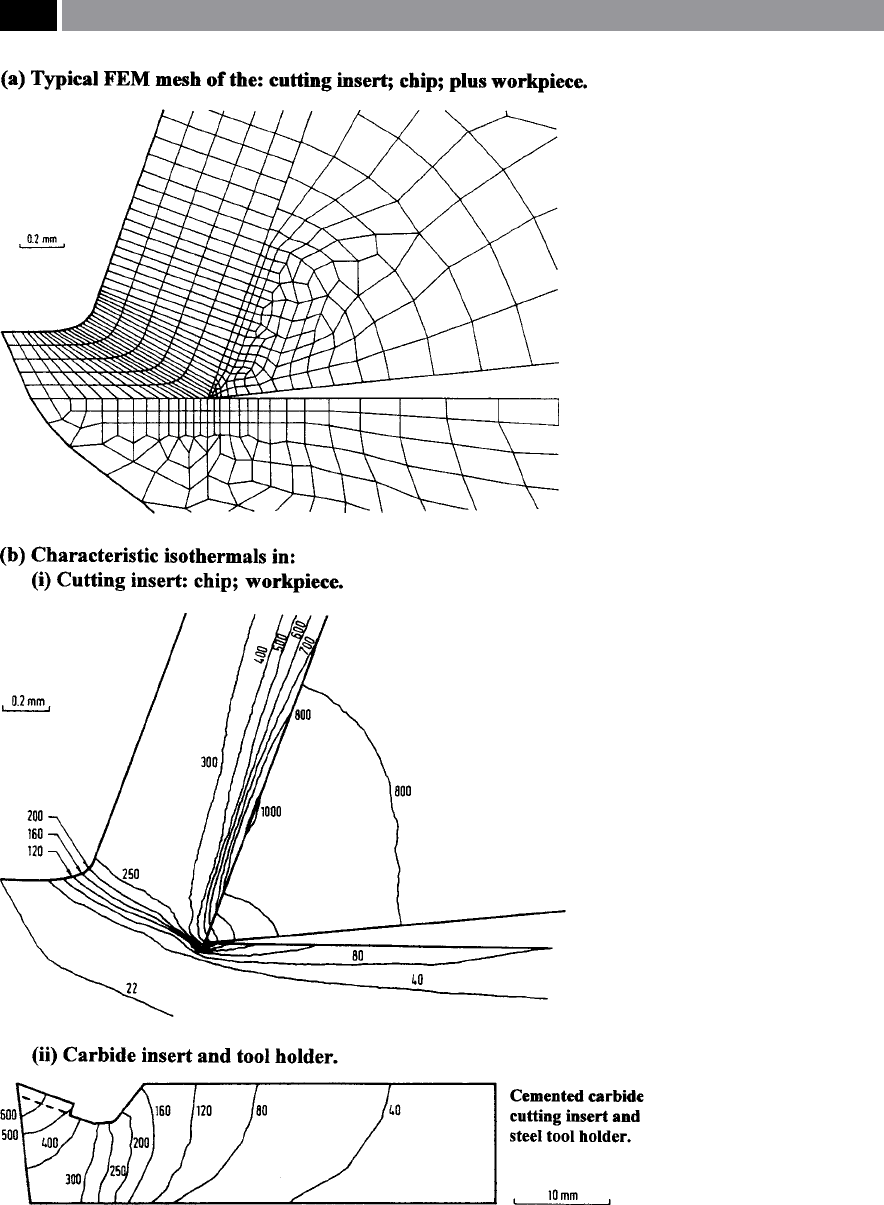
Figure 173. Finite Element Method (FEM), to obtain simulated, but realistic data on isother-
mal temperatures within the cutting region. [Source: Tay et al., 1993]
.
332 Chapter 7
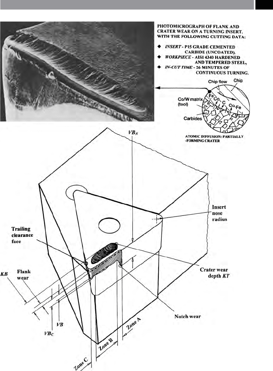
Figure 174. Typical wear patterns that could be present on a cemented carbide (uncoated) cutting insert, utilised
under ‘steady-state’ turning conditions
.
Machinability and Surface Integrity 333

•
good quality and consistent workpiece material is
to be utilised;
•
that the condition monitoring of machine tool en-
sures that it is in an optimum state for use;
•
any ood coolant supply and quality – if it is to be
used – is of the correct grade and dilution concen-
tration;
•
work-holding/support is both rigid and precise/ac-
curate;
•
expert support is available – if necessary – along
with the user’s own practical experiences.
ese factors oer a good ‘start-point’ in ensuring that
the ‘ideal’ tool wear development takes place.
Classification of Tool Wear Types
Tool wear depends on several inter-related factors,
some of these have been mentioned above, but are
worth restating, such as: the cutting insert and work-
piece material combination – plus their physical,
m
echanical and chemical properties; cutting insert ge-
ometry; as well as cutting uid properties and pressure
– if applied; together with various other operational
parameters – cutting data selected, stability of the cut-
ting process and work-holding application techniques.
Any knowledge obtained on analytical studies of wear
mechanisms, is largely based upon the results from ex-
perimental trials. Simply obtaining wear data presents
considerable diculties, then simply analysing these
results can be somewhat onerous, due to isolating the
major cause of this particular wear regime. Neverthe-
less, having stated these problems, many potential so-
lutions to specic wear patterns can be found, so long
as the actual wear regime, or composite wear behav-
iour can be singularly identied. With this in mind,
the following classications for tool wear are given be-
low (i.e. see Fig. 174 for of several these wear patterns),
which include:
•
Flank wear – as its title suggests, occurs on the cut-
ting edge’s anks, usually the result of an abrasive
wear mechanism. Both of the clearance faces – lead-
ing and trailing edges, together with the tool nose
radius are subject to a parallel land wear, created by
the workpiece travelling past the contact regions of
the tool both during and aer chip formation. Such
a wear mechanism is considered normal tribologi-
cal behaviour and a progressive form of ank wear
can be tolerated and subsequently dealt with, by an
ecient tool-changing strategy, based upon antici-
pated tool life expectancy.
NB T
oward the end of the steady-state and progres-
sive ank wear regime, it could lead to several un-
desirable factors, such as: increasing friction, which
can possibly change the insert’s prole – leading to
poor machined surface texture, or dimensional in-
accuracies as the ‘
tool dris’
63
– creating variability
in tolerances of successive parts.
•
Crater wear – this is present on the rake, or chip
face and is normally the result of a combination
of an abrasion and diusion
64
wear mechanism.
63 ‘Tool driing’ , is a term used to describe the fact that having
initially set the tool to a particular dimensional size, the tool’s
ank will progressively wear – under steady-state machin-
ing conditions. e variability in dimensional size can be the
subject of both random and systematic errors – even when
the operation is behaving normally. is dimensional variabil-
ity, causes for example: turned diameters to get larger, while
drilled holes get smaller – as successive components are ma-
chined, this is the essence of tool-driing. e term process
capability* has been coined to explain the stochastic process
output from a normally-operating production process – see
Chapter 2, Footnote 26, for more information regarding this
subject.
*Process capability (C
p
) can change during consecutive pro-
duction output of components, being the result of the ‘vari-
ables’ (i.e. as each singular part dimension is known), pro-
ducing either random, or systematic errors, or both, as the
production run progresses. is is why it is usual practice to
utilise ‘Statistical control techniques’ to show any signicant
changes in output. erefore, ‘Shewart charting techniques’
in combination with ‘Probability paper’ are employed, to esti-
mate the: C
p
value and to determine if the process is behaving/
operating ‘normally’ – usually a ‘normal output’ is signied by
establishing a ‘straight-line’ (i.e. plotted) relationship on the
‘Probability paper’.
64 ‘Diusion wear’ ,
was initially proposed in 1858 by the Ger-
man physiologist Adolph Fick (1829–1901), where he enun-
ciated laws governing the diusion of substances generally
on a quantitative basis. Today, we are concerned with ‘atomic
migration’ within metallic solid solutions. Fick produced two
laws, with Fick’s 1
st
Law stating: ‘at the amount (J) of a ma-
terial moving across a unit area of a plane in unit time is pro-
portional to the concentration gradient (∂c/∂x) at the same time
but of opposite sign’. It can be expressed as follows:
J[atoms/m
2
.s] = − D [m
2
/s](∂c/∂x)[atoms/m
3
.1/m] Fick’s 1
st
Law Where: J = ux, net ow of atoms; D = diusion coe-
cient; ∂c/∂x = concentration gradient.
NB Assuming that X-axis is parallel to direction in which
concentration gradient is operating. Fick’s 2
nd
Law was de-
rived from the 1
st
Law and from the fact that matter is con-
served, relating the change in concentration with time (∂c/∂t)
and it can be expressed as: (∂c/∂t) = ∂/∂x (D∂c/∂x)
Fick’s 2
nd
Law (General case) By dierential calculus, this 2
nd
Law changes to: ∂c/∂t) = D ∂
2
c/∂x
2
.
334 Chapter 7

e crater can be formed either via a hard-particle
grinding action, which mechanically-removes rake
face surface layers, or by a complex ‘atomic diusion
pr
ocess’
65
interacting between the chip and the tool
material (ie see Fig. 174 – top right).
NB I
f a cutting insert has high bulk hardness,
combined with ‘h
ot-hardness’
66
, plus minimum af-
nity between these two materials, this will dimin-
ish any crater wearing tendencies. Moreover, crater
wear changes the cutting insert geometry of the
edge, which may impair chip formation and modify
cutting forces, or lead to a weakened edge strength.
Many of today’s multi-coated cutting inserts are less
aected by crater wear than their uncoated coun-
terparts.
NB From this it can be appreciated why the nal stages of dif-
fusion are somewhat slow, due to the rate of diusion decreas-
ing as the concentration gradient diminishes. (Higgins, 1979)
65 ‘Atomic diusion process’ ,
there is strong evidence – when
ferrous workpiece machining – to indicate that cratering of
WC-Co cutting inserts (i.e. uncoated), occurs by diusion of
the C atoms into chip at the interface (i.e see Fig. 174 – top
right schematic diagram). Remembering that solid-state dif-
fusion depends upon the rate at which the tool’s atoms dis-
solve/diuse into the chip. For WC, the most rapid diusion is
by the tool’s Co atoms – of the carbide bond and, the Fe atoms
from the chip. Hence the carbide grains are undermined and
swept-away for two reasons:With WC tool material, carbide
grains are not isolated and constitute the bulk of the mate-
rial, so support each other in a ‘rigid framework’ ,Due to Co
atoms from the tool ‘diusing-out’ , so Fe atoms from the chip
‘diuse-in’ and these provide support for the carbide grains,
which in turn inhibit their removal. In the chip, C atoms being
small, rapidly diuse through the Fe matrix, however those in
the tool are strongly-bonded to W and are not free to move by
themselves. us, the rate of diusion of both W and C atoms
together from the tool go into the chip and thus, will control
diusion wear with respect to its temperature – as Fick’s Laws
suggest.
NB e distances for diusion at the tool/chip interface are
between 1 nm up to 1µm. Diusion in the tertiary shear zone
(i.e. ank) is normally higher than in the secondary shear
zone, due to the signicantly greater workpiece surface speed
in this vicinity. So, not only is attrition a mechanism for ank
wear, diusion is also partly responsible – even when the rake
face is hardly worn. In appearance, when the grains look to
be smooth, this is a good indication of a diusion mechanism
taking place. (Armarego and Brown, 1969)
66 ‘Hot hardness’ ,
this is the ability of a cutting insert to retain
its relative bulk hardness and hence geometry at elevated tem-
peratures.
•
Plastic deformation – occurs when high pressures
(i.e. compression) are exerted on the cutting edge
in combination with elevated temperatures. Con-
ditions likely to create plastic deformation on the
cutting insert are when high speeds and feeds are
utilised on workpiece materials that are prone to
work-hardening. Tool materials must have the re-
quired mechanical properties to withstand plastic
deformation during machining. Typically, bulging
of the edge in the tool nose region, leads to: geom-
etry deformation; chip ow modication; greater
localised temperatures – until a critical juncture is
attained. So cutting insert ‘hot-hardness’ is a vital
characteristic.
NB I
n order to combat cutting insert plastic defor-
mation, a large tool nose radius, plus more robust
tool geometry adds greater strength in this ‘exposed
region’ of the tool.
•
Notch wear on insert’s leading edge – is the result of
mechanical action, promoted by either machining
workpiece materials that may easily work-harden,
so each successive longitudinal turning pass at the
same D
OC
leads to the previous surface condition
being harder, resulting in a more abrading-action
here – hence a notch will wear at this point on the
insert‘s ank. is ‘notching eect‘ can be reduced,
if a variable D
OC
is employed, to ‘even-out’ the con-
tact region along the leading edge of the insert.
NB ‘
Black-bar stock’ having been hot-rolled from
its primary processing route, tends to have a hard
and abrasive oxide scale to its periphery, which may
contribute to insert notching when only the surface
is ‘skimmed’ by a longitudinal turning operation.
•
Notch wear on insert’s trailing edge – occurs by in
the main, by adhesion wear, but to a lesser extent,
may be the result of an oxidation wear mechanism.
e notch on this ank’s trailing edge is formed
where the cutting edge and the workpiece material
separate.
NB N
otch wear here, tends to be very localised to-
ward the end of the cut, enabling air to reach this
cutting vicinity, which has a high temperature pres-
ent, so adhesion/oxidation can be expected.
•
Built-up edge (BUE) formation – is usually the re-
sult of tool/workpiece anity associated with tem-
Machinability and Surface Integrity 335

perature and its respective cutting speed (i.e. see
Fig. 28). Moreover, it can also transpire as a result
of ‘edge agging’ , or from other wear mechanisms.
is ‘cold’ pressure-welded workpiece material be-
ing attached to the tool as a BUE, changes the cut-
ting insert’s geometry – to its detriment. Hence,
this BUE is both severely work-hardened and
‘unstable’ – it will break-away from the tool mate-
rial thereby potentially ‘frittering’ the insert’s edge.
NB BUE machining data conditions have been
reasonably well-dened, so fortunately, these re-
spective cutting speeds can be avoided, particu-
larly, as most CNC machining operations happen at
much higher speeds and modern insert grades and
coatings, minimise this BUE eect. If BUE does oc-
cur, it can create a poor surface nish on the ma-
chined surface. In any BUE machining condition,
if it continues without attention, then the result can
be rapid edge breakdown, or even result in insert
fracture.
•
e former conditions are in the main, conned
to continuous cutting and steady-state machining
conditions, albeit with single-point cutting inserts.
•
e latter conditions are generally restricted to in-
termittent cutting multi-point machining, or inter-
rupted cutting operations:
•
ermal cracking – is usually the result of fatigue
wear, produced by thermal cycling machining con-
ditions, such as when milling. ese cracks that
form are normally at 90° to that of the cutting edge
67
.
ese cracks are spaced out periodically along the
cutting edge and when they propagate (i.e. grow) to
67 ‘ermal fatigue cracks’ , are usually termed ‘comb-cracks’ –
due to their appearance is not unlike that of a hair comb. When
these cracks propagate to a critical length which can be ex-
plained in terms of ‘Fracture mechanics’* and in particular the
‘stress intensity factor’ (K
IC
) – with the ‘C’ standing for ‘critical’.
Such cracks will fracture quickly around the ‘Speed of sound’
(i.e. Mach 1, or in a steel workpiece @ 5050 ms
–1
), so little, if
any warning is given of the likely failure condition as it arises
– when the tool’s edge eventually catastrophically fails.
*In 1957, G.R. Irwin and his co-workers, laid the foundations
for ‘Fracture mechanics’ and were particularly noted for the
mathematics for dening the ‘stress intensity factor’ (K), spe-
cically:
K = σ √ (πc) [Nm
½
]
Where: σ = fracture stress, c = half length of an internal aw.
(Shaw, 1984)
a critical size, bulk tool material will be pulled-out
of the tool’s edge – leading to a very rapid type of
cutting insert edge failure.
NB Varying the chip thickness will also aect tem-
peratures throughout the cut. A cautionary note
here, concerning cutting uid application: if used
under certain conditions, the cutting uid has a
detrimental inuence in some metal cutting opera-
tions, as it amplies the variations in temperature
between and in- and out-of-cut.
•
Mechanical fatigue cracking – may be present if
cutting force shock-loads are extreme. Fatigue
68
is
a form of fracture which is promoted by continual
variations in load, but where the load in itself, is not
great enough to cause fracture.
68 ‘Fatigue’ , can be dened as a: ‘Phenomenon leading to the fail-
ure of a part under repeated, or uctuating stress below the ten-
sile strength of the material.’ Failure usually occurs suddenly as
a result of crack propagation without plastic deformation at a
stress level well below that of the elastic limit for the material.
e stress can be either an: ‘alternating’; ‘repeated’; or a combi-
nation of these types. At a discontinuity such as a notch, hole,
or step, the stress is considerably greater and is termed a ‘stress
concentration factor’ (K). Graphs can be plotted , such as:
SN curves (i.e. to nd the endurance limit for steels, or for
non-ferrous metals, alloys and plastics -the fatigue stress
‘σ
FS
’ is specied for a nite number of stress reversals),
Soderberg diagram – for steel, with alternating stress plot-
ted against steady stress. Moreover, a ‘safety factor’ (FS) can
be applied to the graphical result, as follows:
(Safety factor)
FS =
σ
y
σ
m
+(σ
y
�σ
e
)K σ
r
Where: σ
y
= yield stress, σ
m
= steady stress component,
σ
e
= failure occurs – (i.e. above a line drawn from this value:
σ
e
on the ‘Y-axis’ to σ
u
on the ‘X-axis’); Kσ
r
= alternating com-
ponent – with ‘K’ representing the ‘stress concentration factor’
and ‘σ
r
’ representing ‘alternating stress’.
NB Most steels have an ‘endurance limit’ being about half its
tensile strength, with an approximation oen utilised:
For steels: Endurance limit = 0.5 tensile strength (i.e. up to
a tensile strength of 1400 N mm
–2
), Endurance limit = 700
N mm
–2
(i.e. above a tensile strength of 1400 N mm
–2
).
For Cast steel/iron: Endurance limit = 0.45 tensile strength (i.e.
up to tensile strength of 600 N mm
–2
), Endurance limit = 275
N mm
–2
(i.e. above a tensile strength of 600 N mm
–2
).
Non-ferrous metals/alloys: there is no endurance limit and
the fatigue stress is taken at a denitive value of stress rever-
sals, e.g. 5 x 10
7
. (Carvil, 1994, et al.)
–
–
336 Chapter 7

NB erefore at the initiation of a cut, the varia-
tions in the magnitude of the cutting force and its
direction, may not be too great for both the tough-
ness and strength of the cutting insert. With con-
tinual usage however, these fatigue cracks grow – in
the main – parallel to the cutting edge and may
eventually be the cause for premature tool failure.
•
Cutting edge chipping – this transpires when the
edge line fractures, rather than being the result of
wear. It can be considered as a form of fatigue fail-
ure, because of the cycles of loading and unloading
during cutting, leading to particles of tool material
being removed from the insert’s surface. is type
of wear mechanism is generally the result of inter-
mittent cutting operations.
NB A
n investigation into whether this edge wear
is either from chipping, or the result of ank wear.
‘Spalling’ (i.e. cracking, or aking of the surface)
and ‘nicking’’ are also variants of this category of
edge degeneration.
•
Fracture – is normally catastrophic conclusion to
the cutting process (i.e. see Fig. 175). Here, bulk
material fracture can have serious consequences
obviously to the cutting insert, but also aecting
the machined part. Moreover, this form of edge
fracture is more oen than not, the termination of
alternative wear regimes.
If Fig. 175 is investigated in more detail, it may help
comprehension of the nature of the serious problems
associated with such a sudden failure mode. e cut-
ting insert was purposely catastrophically failed in
practical trials conducted by the author, using a rea-
sonably robust turning and facing geometry, longitu-
dinal turning P/M ferrous compacts without coolant.
Here, the cutting speed was raised by 25% above the
optimum, with the feedrate 40% greater than usually
s
pecied. is ‘abusive machining regime’ , created
high ank wear and plastic deformation to the cutting
edge, which shortly failed – catastrophically. In Fig.
175c, detail of the fracture surface indicates both duc-
tile and brittle failure modes instigated from the worn
leading edge’s ank. By increasing the cutting data by
just the cutting speed alone and leaving the feedrate
at the optimum, tool life was reduced on other simi-
lar inserts, but catastrophic failure did not occur, only
very high levels of ank wear. However, if the cutting
speed was kept at the optimum and the feedrate was
increased – as mentioned – in-line with other insert
trials, then catastrophic failure eventually occurred,
well before that predicted by ‘Taylor’s tool life calcu-
l
ation’ . is conrmed the fact that the high abrasive
nature to the testpieces produced from ferrous-based
P/M compacts, in combination with an increased fee-
drate caused premature catastrophic failure of the cut-
ting inserts during these ‘harsh’ machinability trials.
As previously mentioned, Appendix 11 has a con-
cise ‘trouble-shooting guide’ for some of the potential
wear regimes that are likely to be experienced during
many machining operations.
7.7.2 Tool Life
Introduction
It is normal practise to assess tool life according to
three mutually-inuencing criteria, as any one of them
could be the reason for the expensive business of sub-
sequent part scrappage. ese criteria that signicantly
aect machined components and can be the reason for
curtailment of the cutting tool’s life are:
1. A
bility to sustain workpiece tolerances – here if
the tool has been in operation for too long ‘in-cut’ ,
then this will increase the tendency for ‘tool dri-
ing’ which will amplify machined component vari-
ability, while creating inconsistency in part produc-
tion (Figs. 31ci and ii),
2. M
aintaining machined surface texture quality – as
the tool is progressively utilised, the ank and cra-
ter wearing tendencies will increase, leading to de-
generation of the surface texture, below that which
was demanded from the designer’s direct engineer-
ing requirements (i.e. see graph in Fig. 148),
3. E
ciency in chip-breaking ability – if the cut-
ting insert/tool has been operated for considerable
time, there is every expectation that both ank and
more importantly crater wear will be present. is
will have an adverse eect on chip-breaking ability,
leading to either poor component surface texture,
or variability in component tolerances, or both
(Figs. 37 and 38a and b).
If a cutting insert, or tool no longer satises the above
wear criteria, its useful life is ended and it should be
summarily discarded. e tool life’s predictability, is a
key factor in an estimation of the anticipated produc-
tivity output level. Approached from a dierent direc-
tion, an CNC programmer may deliberately choose
Machinability and Surface Integrity 337
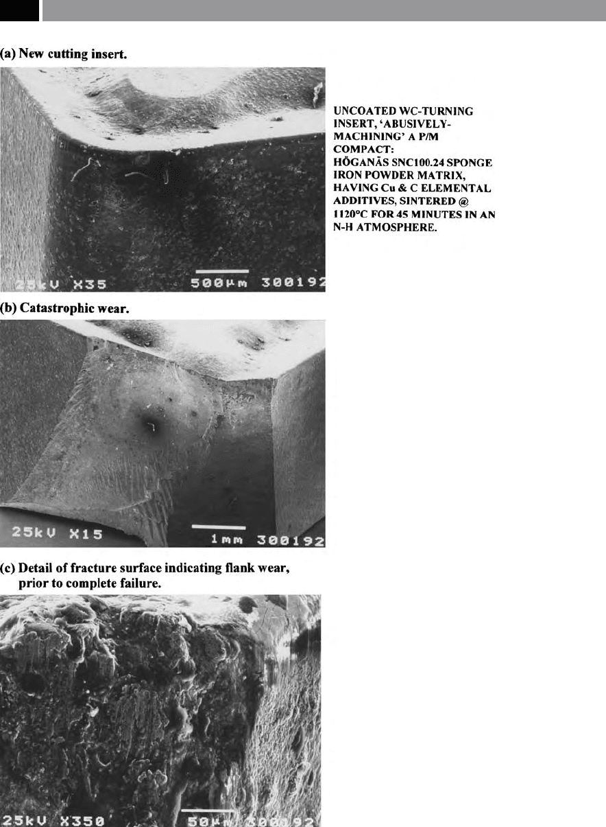
Figure 175. Catastrophic failure of a turning insert.
338 Chapter 7

the cutting insert, or tool they are most familiar with,
because they know – from practical experience – that
it performs and wears in a progressive manner, rather
than the unpredictability associated with an insert of
‘uncertain machining capability’ that might otherwise
prematurely fail.
Prior to discussing criteria for determining when
a
cutting insert is ‘worn-out’ , it is necessary to estab-
lish in practice, what this actually means. For example,
does ‘worn-out’ refer to when the: dimensional accu-
racy becomes unpredictable: or if the surface nish has
signicantly deteriorated; or perhaps the fact that its
automatic chip-breaking behaviour has become inef-
cient? In many situations it is by the user’s experience
that one can judge how much ank wear can be toler-
ated on the cutting edge before machining is discon-
tinued. As a rule, ank wear is a dependable criterion
for assessing when the cutting edge is eectively worn-
out. Moreover, from the previous discussion, perhaps
the degree of cratering may in certain machining cir-
cumstances prove to be more signicant than the ank
wear, in respect to the shortening tool life.
Tool wear can be established by several techniques,
but the usual method is to observe and then measure
the actual wear as it progressively develops. e eec-
tive cutting time, or tool life ‘T’ ,
is specied as time-
elapsed prior to a predetermined degree of wear has
been reached. A typical procedure for determining
ank wear can be: to observe cutting edge(s) in-situ on
the machine tool; then remove from the machine and
visually inspect the tooling; followed by its respective
wear rate can then be optically magnied in suitable
equipment allowing accurate dimensional measure-
ment – against the following criterion (i.e. see Fig.
174):
•
Extent of ank wear from original edge – if this
wear is of relatively uniform nature, it may be dis-
tributed across three zones, ‘A’ ,
‘B’ and ‘C’. e
mean ank wear ‘V
B,C–A
’ is measured over the cut-
ting region of the leading edge across these zones –
it is oen just referred to as simply: ‘V
B
’. If excessive
wear develops at one position on the cutting edge,
for instance where the wear-notch ‘V
N
’ occurs, this
zone is usually ignored when establishing the ‘mean
wear’. Here and under these conditions, it is usual
to quote the maximum ank wear as ‘V
Bmax
’ ,
•
Extent of cratering – this is usually specied by
the maximum crater depth from the plane of the
original rake face ‘K
T
’ and in some cases, by its di-
mensional size: ‘K
B
’- width and ‘K
M
’ – length (not
shown).
e above wear criteria, are normally utilised for esti-
mating the extent of ank and crater wear. Over many
years of experimental research into tribological wear
mechanisms, it has been established that progressive
ank wear develops according to a xed pattern, with
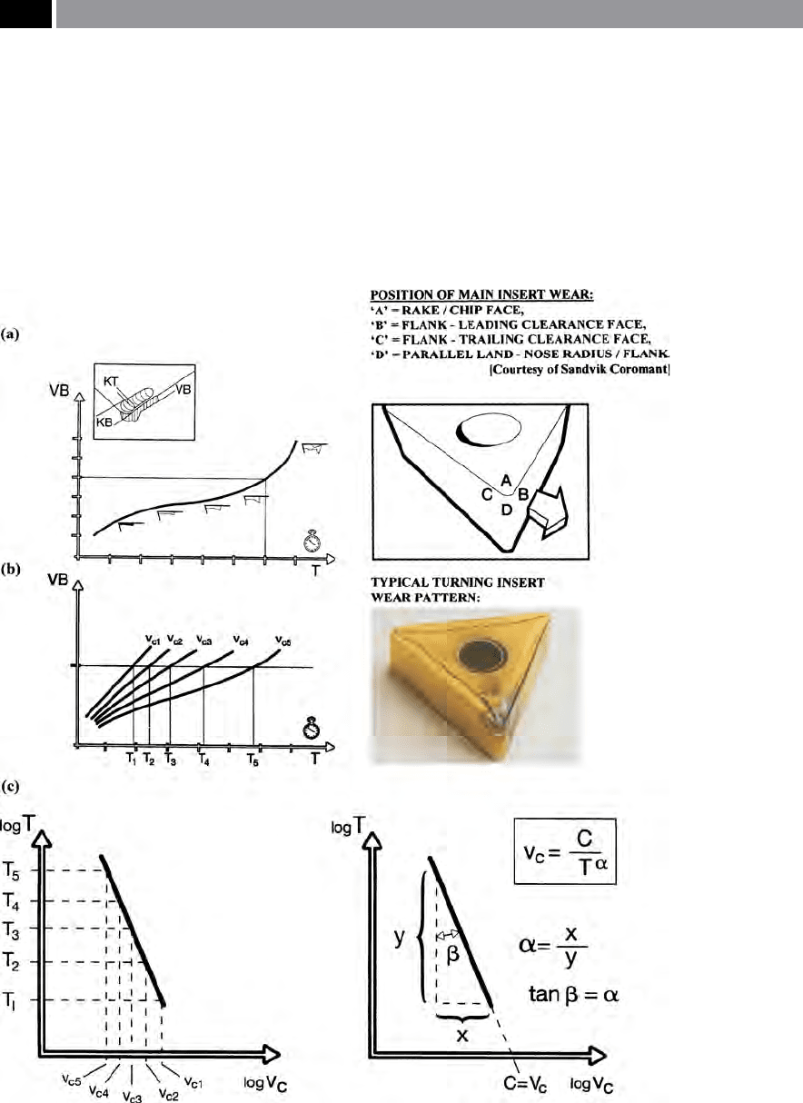
three distinct stages to this wear regime, they are (Fig.
176):
1. Initial, or primary wear – if a new cutting edge
is used to machine a workpiece, there is a rapid
breakdown of the of the cutting edge. is early
ank wear on the tooling is depicted in the graph
of wear against time in Fig. 176a, indicated by its
preliminary high wear-rate, is wear-rate is de-
pendent upon the cutting conditions and type of
workpiece material, plus any cutting uid applica-
tion – if utilised. Flank wear increases in relation to
an higher cutting speeds,
2. Progressive, or secondary wear – occurs aer the
initial ank wear has taken place. During the fol-
lowing time period, there is a steady and progres-
sive stage to the cutting tool’s/insert’s wear, with a
much less pronounced increase than that indicated
at the initial wear stage, this is when the productive
machining output occurs. Toward the end of this
progressive wear stage, this being the case when the
ank wear ‘V
B
’ reaches approximately 0.8 mm in
height, here, it is normal practice to replace this old
tool with a ‘sister tool’ – to continue machining the
component batch, or production run. Once ank
wear has reached this arbitrary dimensional value,
then to all practical purposes its productive life is
ended,
3. Catastrophic, or tertiary wear – will normally only
become apparent if the tool is taken toward, or up
to, its complete failure. Such catastrophic failure
is the result of a combination of several tool wear
mechanisms: high ank wear; large crater forma-
tion – reaching the point where the tool has been
suciently weakened for the increased tool forces
now operating to cause it to fracture. Inevitably, if
such an immediate breakdown occurs during the
nal pass over the workpiece’s surface, it is prob-
able that the component has to be scrapped. If the
workpiece has a high residual raw-stock value, then
aer machining, signicantly more added-value
will have accrued. So, any initial savings made by
using these tools into the tertiary ank wear stage,
will be more than cancelled-out by scrapping this
component!
Machinability and Surface Integrity 339
Tool-life Diagrams
Machinability is a subject that has yet to be fully-de-
ned and analysed, in particular the interactive mech-
anisms that take place at the chip/tool interface, with
the user’s own experience being a good start-point for
any future machining operations. As has been men-
tioned above, tool wear varieties can have several dif-
fering causes and eects (i.e. see Appendix 11). With
any machining batch, or production run, it is custom-
ary practice to establish a ‘norm’ for both the tolerable
ank wear dimension and the depth/size of crater for-
mation. In particular, as the ank wear pattern usu-
ally takes in-cut time to progressively develop and this
predictable tool/wear relationship has been well estab-
lished some years ago, initially by F.W. Taylor’s pio-
Figure 176. Tool wear under steady-state conditions: (a) tool wear as a function of time, (b) if cutting speed
is changed, then tool life is aected, (c) amalgamation of these ‘Taylor curves’ and derivation of the ‘general
taylor curve’. [Courtesy of Sandvik Coromant]
.
340 Chapter 7

neering work, then further rened over the years. As
can be seen from the graph of ank wear (V
B
) against
time (T)
69
shown in Fig. 176a, tool wear does not usu-
ally follow a straight-line relationship’. Invariably, the
‘V-T curve’ for ank wear initially develops quickly
then settles to a moderate growth over a reasonable
time-period, then has a rapid escalation – almost ex-
ponentially – at an ‘end-point’ as it catastrophically
fails. e actual plotted wear curve prole and its as-
sociated inclination angle will vary depending upon
the cutting speed selected, with individual cutting
speeds having specic wear curves (i.e. see Fig. 176b).
So from the graph in Fig. 176b, it can be visually-es-
tablished that the higher the cutting speed utilised, the
greater the ank wear. e composite graph depicted
i
n Fig. 176c – le (i.e. taking ‘standardised’ ank wear
@ times: T
1
to T
5
– from Graph 176b), shows that a
direct relationship exists between logarithmic time
(logT) and cutting speed (logV
C
). e features that
characterise this ‘straight-line’ are its position and gra-
dient, these values can be expressed through the ‘gen-
eral-case’ tool formula
70
developed by Taylor (1907),
as follows:
V T
α
= C
69 ‘Cutting time’ (T) here, is the tool-life of the cutting edge, be-
fore a specic amount of ank wear ‘V
B
’ is established.
70 is ‘general case’ Taylor formula, has been expanded and
developed which denes the machining characteristics with
m
ore mathematical rigour, including the eects of: feed-
rate; D
OC
; as well as component hardness, as follows: V T
α
f
m
d
p
H
q
= K T
ref
α
f
ref
m
d
ref
p
H
ref
q
Where: ‘f’ = feedrate (mm rev
–1
),
‘d’ = D
OC
(mm), ‘H’ = Hardness (e.g. HR
C
), with ‘m’ , ‘p’ and ‘q’
are exponents whose values are experimentally-established
for the production operation, ‘K’ = a constant analogous to
‘C’ , while ‘T
ref
’ , ‘f
ref
’ , ‘d
ref
’ , and ‘H
ref
’ are the reference values for
feedrate, D
OC
– when they are <1.0*. *is 1.0 numerical value,
indicates the greater eect of cutting speed on tool life, since
the exponent of ‘V’ is 1.0. Moreover, aer cutting speed, the
feedrate is the next in importance, so ‘m’ has a value > ‘p’**.
**e exponent for work hardness ‘q’ is also <1.0.In reality,
there are diculties in the application of the above equation
for practical machining operations, due to the vast amount of
machining data that is necessary to determine the parameters
of this equation – producing considerable statistical variance.
In order to reduce the variability, while making the overall
equation more manageable, the D
OC
and hardness parameters,
reduce the equation to the following expression:
V T
α
f
m
= K T
ref
α
f
ref
m
Where: ‘terms’ are the same, but the parameter ‘K’ will have
a slightly dierent interpretation – see the available literature
for a more rigrous mathematical treatment on the subject of
tool life. (Groover et al., 2002)
e two constants (α, C), can be established graphi-
cally from the graph (Fig. 176c – right) of the ‘plot-
ted’ sloping straight-line gradient. Hence, the value
of constant ‘α’ ,
can be obtained graphically from the
trigonometrically relationship of the respective values
of the ‘X’ and ‘Y’ coordinates. Likewise, the other con-
stant ‘C’ ,
may be found by extrapolating this sloping
line down to the cutting speed axis (logV
C
), for its nu-
merical value.
Tool Costs
e tool cost ‘CT’ will normally consist of the sum of
the purchase cost, grinding costs – where applicable,
as well as tool-changing cost for each machined com-
ponent. In Table 12 (below), it tabulates how tooling-
Table 12. Calculating the cutting-tool cost per cutting edge
Costs for: cutting tool, edges and
regrinding:
Sum of costs:
Initial cost of tool = (A)
Number of cutting edges per tool = (B)
Tool cost per cutting edge = (A/B)
= (C)
Cost of insert = (D)
Number of cutting edges per insert = (E)
Insert cost per cutting edge = (D/E)
= (F)
Machine charges per hour = (G)
Tool changing time (minutes) = (H)
Cost per tool change = (G x H/60)
= (I)
Regrinding charges per hour = (J)
Regrinding time (minutes) = (K)
Regrinding cost = (J x K/60)
= (L)
Tool cost per edge =
(C + F + I + L)
= (M)
Number of components per cutting edge = (N)
Tooling cost/component (i.e Cutting tool
cost per edge)
= (M/N)
= (C
T
)
.
Machinability and Surface Integrity 341