Smith G.T. Cutting Tool Technology: Industrial Handbook
Подождите немного. Документ загружается.


nants. e outermost adsorbate layer is oen termed
the ‘
Beilby layer’
82
: ≈1 µm in thickness and consisting
of many complex factors. Notably, this ‘layer’ would
more than likely have hydrocarbons present and wa-
ter vapour, that originated in the coolant, or the at-
mospheric environment, respectively. Underneath
t
his metallic surface for work-hardening materials,
there is normally a plastically-strained region that has
usually been metallurgically altered. e depth of this
strain-hardened layer will vary somewhat, but it is in
t
he region of 10 µm, its actual thickness is dependent
upon the amount of plastic deformation induced by
the tool’s passage over the surface and is inuenced by
the metallic substrate’s composition. e plastic defor-
mation and work-hardening depths
83
, can penetrate
to fractions of a millimetre this is particular true, if a
‘wiper-insert‘, or roller burnishing tools is employed to
purposely create this localised hardened region to the
component’s surface.
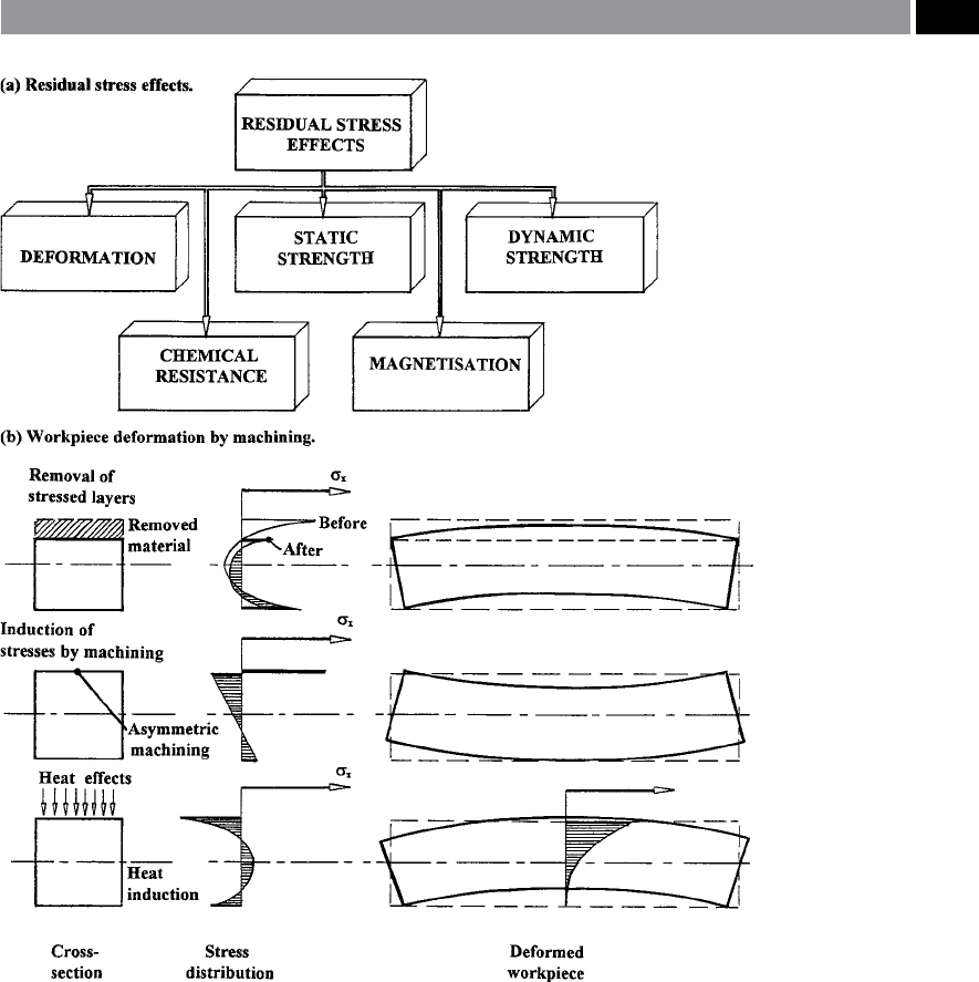
Residual Stress Deformations
For any residual stresses acting within a body (i.e.
component), they will occur without any external
forces, or moments. Internal forces form a system that
is currecntly in a state of equilibrium and if portions
are removed – by machining, the equibrium status is
normally disturbed, resulting in potential component
deformation. is eect of machining distortion is
well-known to practising industrial engineers, when,
for example, machining just one side of a thin compo-
nent, this operation will cause a partial release of local
residual stresses causing it to bend and bow. If either a
casting, or forging has not been heat-treated for stress
relief and its needs asymmetrical machining (i.e. on
one side only), it is likely to deform aer unclamping
restraint from its work-holding device on the machine
tool. In an attempt to minimise this distortion created
by residual stress release, an experienced machinist will
release the clamping forces aer roughing cuts so that
82 ‘Beilby layer’ , on the machined surface is ‘practically amor-
phous’ – this condition being proposed by Sir George Beilby
around the beginning of the 20
th
century.
83 A
s an approximation, the depth of hardness penetration is ap-
proximately 50% to that produced by residual stress penetra-
tion, whereas the observational plastic deformation is about
50% greater than this penetration.
the stressed surfaces are equalised, prior to reclamp-
ing and taking a nish pass. If this unclamping and
then re-clamping activity is not possible, components
clamped in-situ on the machine tool are occasionally
vibrated at their natural frequency, to minimise these
induced residual stresses. Component deformation is
roughly proportional to the removed cross-section of
workpiece material. Any further nishing is usually
concerned with just a light cut to minimise any detri-
mental eects resulting from residual stresses by a pre-
vious production processing operation, or route.
e release of internal residual stresses must not be
confused with the input of such stresses by machin-
ing, as indicated in Fig. 186b. e machining process
generates residual stresses by plastic deformation (Fig.
187a), or from localised metallurgical transforma-
tions. In Fig. 186a, the residual stress eects inuence
a range of mechanical and physical properties of the
workpiece material, such as:
•
Deformation – this point has been alluded to above
and can create problem with small workpiece cross-
sections,
•
Static strength – is aected by the yeild point of the
workpiece material, which in turn, is inuenced by
the presence of residual stresses,
•
Dynamic strength – of the part in-service can oen
have its fatigue strength and life aected by the in-
uence of residual stresses present,
•
Chemical resistance – if certain metals are sub-
jected to induced residual stresses on exposure to
atmosphere over a period of time, then stress corro-
sion may occur,
•
Magnetism – residual stresses present, can aect a
component’s magnetic properties, creating distur-
bances of the crystalline structure.
Taper-Sectioning and Micro-Hardness Assessment
So that an improvement of metallographical inspection
of a sectioned machined surface can be made without
unduly aecting any form of surface distortion, ‘taper-
sectioning’ has oen been utilised. A tapered-section
(Fig. 187b), allows such sub-surface features as: phase
transformations; plastic ow zones; localised cracking;
bulk transportation and redeposit of material; to be in-
vestigated which would otherwise have been missed, if
only prolometry (i.e. surface topography assessment)
had been undertaken.
As its name implies, a taper-section overcomes the
limitation of perpendicular sectioning. By taking an
362 Chapter 7
angular planar slice through the components cross-
section, this modied cut angle enhances the substrate
magnication, without unduly distorting exposed sur-
face features – giving greater discretion when observ-
ing, or testing the surface topography. In Fig. 187b,
an 11° sectional cut improves surface discrimination
by increasing the vertical section magnication by
around ve times. e taper-section angle (TSA) will
thus be 79°, with the vertical magnication being ob-
tained from the following expression:
TSM = s
ecant (TSA)
Where:
TSM = t
aper-section magnication,
TSA = taper-section angle.
Oen, the exposed sub-surface feature of interest that
has been plastically deformed, or mechanically altered
i
s in the main quite small, somewhat less than 0.1 mm
in width. If a micro-hardness indentor such as either
Figure 186. The eects of residual stress and deformations of a workpiece by machining. [After:
Brinksmeier et al., 1982]
.
Machinability and Surface Integrity 363

the Vickers
84
, or the Knoop
85
is utilised (Fig. 187c) to
establish hardness readings in the vicinity of this re-
sidual stress zone, then more indentations are possible
using the Knoop, rather than the Vickers indentor, giv-
ing, more discrimination to the ‘foot-printing’ assess-
ment. A note of caution here when originally attempt-
ing to take the taper-section, is that it is quite possible
to metallurgical alter the sub-surface features, if when
taking the section too much heat is induced when cut-
ting it from the parent component. is comment is
also a valid statement for the subsequent grinding and
polishing of the removed taper-section, prior to metal-
lographical/hardness assessment.
Surface Condition – Being
Affected by Cutting Speed
Prior to discussing the surface and sub-surface modi-
cations to the machined part – shortly to follow, it
is worth taking a closer look at the series of photo-
micrograph images shown in Fig. 188. Here, a group
of identical metallurgical composition ferrous work-
pieces was machined, but at various cutting speeds.
It can be demonstrated that the role played in aect-
ing the machined surface condition, is signicantly
inuenced by the cutting speed, with its accompany-
ing amplication of induced temperature eects as
‘speeds’ are increased. Moreover, it can also be said,
84 ‘Vickers indentor’ , has a square-based dymond pyramid with
and indentor included angle of 136°. Its indentation is dened
as: ‘e load divided by the surface area of the indentation’. e
Vickers hardness [i.e. penetration] number (VPN), may be
determined from the following expression:
VPN = 2Psin(θ/2)/L
2
Where: P = applied load (kg), L = average length of diagonals
(mm), θ = angle between opposite faces of diamond (136°).
85 ‘Knoop indentor’ ,
has complex facets to its diamond indentor,
having angle of 130° (Short diagonal) and 172.5° (Long diago-
nal), respectively. is facet geometric indentor arrangement
(i.e. having a diagonal ratio of 7:1), leaves a signicantly nar-
rower and longer surface indentation, to that of the Vickers –
mentioned in Footnote 84. us, the Knoop hardness number
(KHN) has been dened by the National Bureau of Standards
(USA), as: ‘e applied load divided by the unrecovered pro-
jected area of the indentation’. e following expression relates
to the Knoop’s surface indentation:
KHN = P/A
p
= P/L
2
C
Where: P = applied load (kg), A
p
= unrecovered projected
area of indentation (mm
2
), L = length of long diagonal (mm),
C = constant – supplied by indentor manufacturer.
that a material’s properties are dependent on the strain
rate, with the type and magnitude of tool wear chang-
ing according to the cutting speeds, so simplistically
speaking:
•
Low cutting speeds – wear is normally character-
ised by attrition (i.e. mechanical removal of surface
layers),
•
High cutting speeds – here, attrition gives way to
diusion type wear and ‘Fick’s laws’ dominate the
cutting regime.
NB S
uch ‘broad classications’ of tool wear mech-
anisms occurring, aects the type of: surface pro-
duced; chip formation and strain behaviour.
In some interesting trials undertaken by Watson and
Murphy (1979) – which highlight the disguised nature
of the underlying factors in surface integrity investi-
gations. In this practically-based experimental work,
they used a cemented carbide insert on an alloy steel
(Fig. 188). It was found that the feedrate and D
OC
have
only marginal eects on the sub-surface damage to a
machined workpiece, with the cutting speed being the
most inuential in this situation. is fact has been
established in Fig. 188, when a range of similar work-
piece specimens was machined with the only variable
being the cutting speed, as follows:
•
Photomicrograph a – the machined specimen was
machined at a very low cutting speed (2.6 m min
–1
)
e chip formation was discontinuous and the sur-
face shows an alternating eect of both chip forma-
tion and fracture, with some evidence of deposited
residual BUE. Here, the surface topography is the
result of complex interactions by various eects,
such as changes in shear angle in the contact area
between the tool and chip, plus ‘straining’ causing
increases in the chip thickness. ese phenomena
produce a variety of conditions, from strain-to-
cracking and visually introduces an irregular and
an alternating surface topography,
•
Photomicrographs a to d – cutting speeds in the
range from 11 to 59 m min
–1
, generate a continuous
chip formation. It is evident from these photomi-
crographs (b, c and d), that the surface texture was
gradually improving as the cutting speed increased,
a
lthough even at 59 m min
–1
, there was some indi-
cation of debris from re-deposited BUE here (i.e. in
‘d’),
•
Photomicrograph e – once the ‘optimum’ cutting
speed had been reached (112 m min
–1
– for this ce-
364 Chapter 7
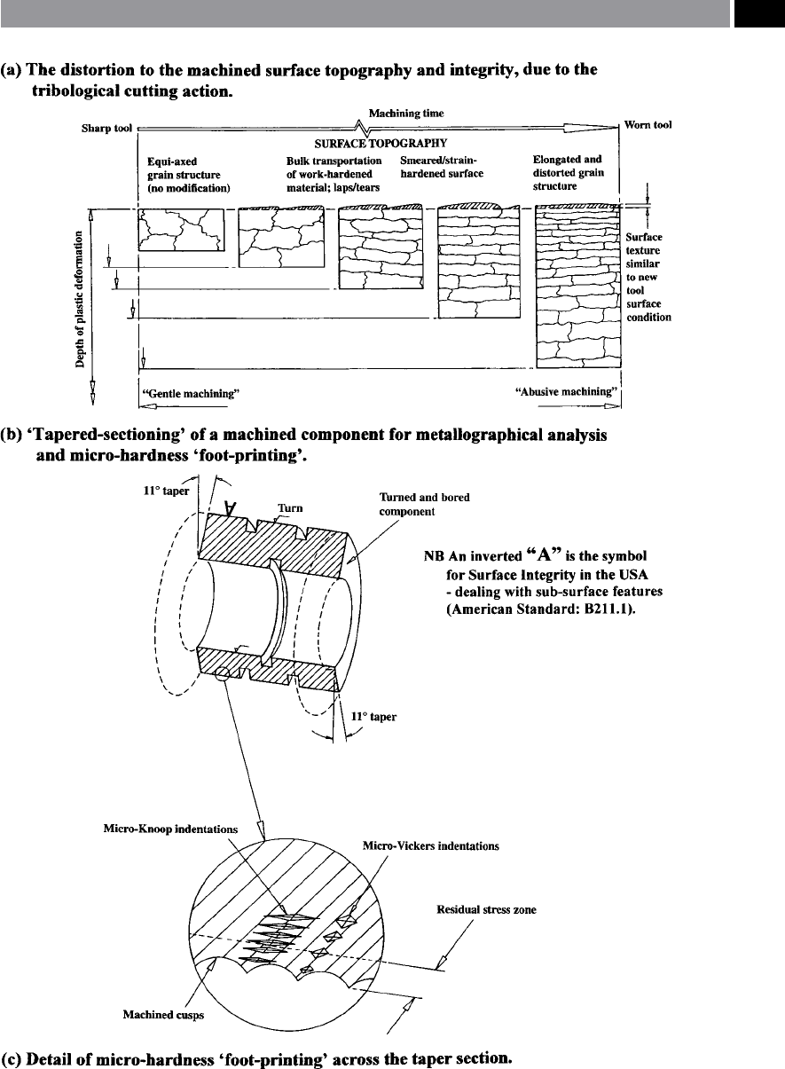
Figure 187. The tribological action of machining and its aect on induced residual stresses and the micro-
hardness ‘foot-printing’ technique
.
Machinability and Surface Integrity 365
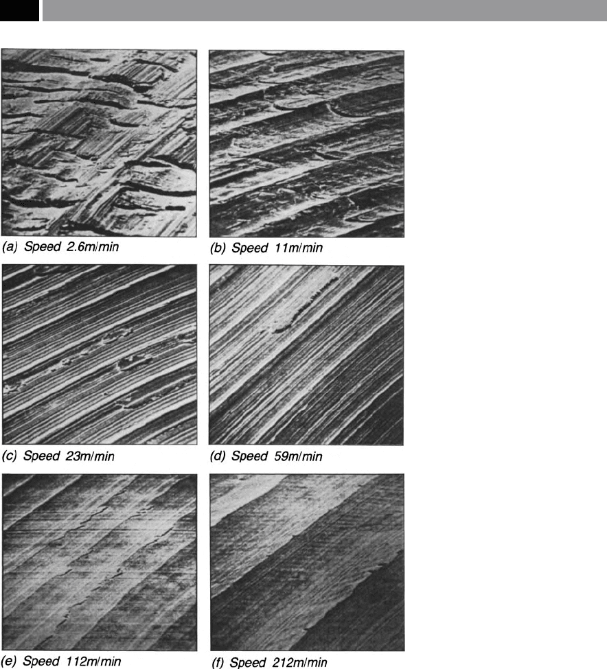
mented carbide insert grade), the surface texture
appears to be in the main, ‘good’ , with only isolated
areas of the topography exhibiting marginal work-
piece side-ow eects,
•
Photomicrograph f – when the cutting speed
was increased to 212 m min
–1
, then in these trials,
greater cutting insert wear-rate occurred and was
attributed to appreciable carbide edge breakdown,
although the surface topography indicated that an
excellent surface texture was present.
e machined surfaces produced at the lower range of
cutting speeds indicated in Figs. 188 a to d, shows evi-
dence of some re-deposited BUE material to greater-
or-lesser extent: having broken away from original
‘
BUE mass’ , then being re-deposited over several
adjacent machined feed cusps (i.e. see Fig. 28a, fully-
appreciate this eect). To obtain a better and deeper
understanding of these machined surface and sub-
surface eects at the extreme conditions of either very
low, or high cutting speeds: Figs. 188 a and f, respec-
Figure 188. Some photomi-
crographs of component surfaces
machined at dierent cutting speeds
– otherwise with identical cutting
data – illustrating the surface, but not
sub-surface steel’s condition. [Source:
Watson & Murphy, 1979]
.
366 Chapter 7

tively, the following comments can be made. When
longitudinal taper-sections were taken through these
specimens’ cross-sections, the ground, polished and
etched surfaces reveal their true substrate damage. In
the case of Fig. 188a, BUE was presents on the sur-
face, moreover, there was a cutting/fracture sequence
indicated with conrmation of work-hardening hav-
ing ‘layered scales’ of with cracks and crevices beneath
them. Conversely, the test specimen machined at high
cutting speed (Fig. 188f), there is some verication of
a ‘white-layer’ formation – which is a complex metal-
lurgical phenomena found in certain ‘abused’ ferrous
workpiece situations – more will be said on this condi-
tion shortly. In fact, the ‘good’ machined surface to-
pography disguises the fact that an underlying ‘white-
layer’ condition was present, having a local recorded
hardness of 860 H
VPN
. By way of comparison, if this
same alloy steel composition had received a ‘conven-
tional’ hardness heat-treatment process: heated and
water-quenched from 1200°C, then the bulk hardness
would only be approximately 700 H
VPN
– see Appendix
12 for Hardness Comparison Tables.
From these examples of cutting speed investigative
results and the previously mentioned discussion, it is
evident that the ‘optimum’ machined surface texture
is obtained when the cutting speed is closely aligned
to that of the tooling manufacturer’s recommenda-
t
ions, so here in this case it is ≈112 m min
–1
, with a
correspondingly ‘good’ surface topography/integ-
rity. If the cutting speeds had been employed at the
‘
higher’ cutting data (i.e. 212 m min
–1
), then one could
have been fooled into accepting this apparently ‘im-
proved’ surface topography. Nevertheless, underlying
this machined surface would be an unstable sub-sur-
face condition, which if used in a stressed and critical
in-service environment, it might potentially fail, by a
reduced fatigue-life – this is why the topic of surface
integrity is so important in today’s climate of potential
industrial litigation, when component failure occurs!
Surface Cracks and White-Layers
If any cracks are present at the free surface which ex-
tends into the material’s substrate, they are potential
sites for premature component failure – for highly
stressed in-service components. It has been reported
in the ndings of industrial enquiries into the UK
railway industry of late, that despite these railroad
tracks being precision machined and then occasion-
ally inspected by non-destructive (NDT)
86
techniques
– according to the maintenance schedule, instances
have occurred when these rails and particular on
high-speed banked corners – have delaminated. is
catastrophic rail delamination has caused several pas-
senger trains to lose contact with the rails and crash,
resulting in signicant loss of life. Hence, the method
of machining – ‘abusive’ – can contribute poor surface
integrity and to the susceptibility of these machined
surfaces to prematurely fail. In the case of milling op-
erations, it has been recognised for a number of years
that up-cut milling – alternatively termed ‘conventional
milling’ (Fig. 190a), can introduce a surface tensile re-
sidual stress into the surface layers of a milled work-
piece. If this machined component is then subjected
to both an arduous and potentially fatigue-inducing
environment, then the cyclical nature of continuous
stressing followed by its immediate stress release, can
initiate surface crack sites causing them to open-up,
which could result in premature part failure. Con-
versely, an identical machined component that has
been ‘down-cut’ – otherwise termed ‘climb-milling’
(Fig. 190b), will induce surface compressive residual
stresses. is surface layer with its residual stress com-
pression, has invariably been shown to remain closed
and thus, avoiding crack propagation and growth,
when machined under identical cutting data and en-
vironmental circumstances. Moreover, for many years,
it has been recommended that for CNC milling appli-
cations ‘climb-milling’ not only generates this favour-
able machined surface compressive stress eect, but is
a more ecient cutting process and as a result, draws
less spindle power. In Appendix 13a and b, two useful
‘nomographs, are given to determine either the cutting
data (Appendix 13a) this is related to the workpiece’s
diameter and, a diagram (Appendix 13b) to obtain the
spindle power from the anticipated chip area, respec-
tively.
In a machined surface, both craters and pits do
not pose too great a fatigue problem, as they cannot
achieve the ‘critical radius’ (i.e see Footnote 67) neces-
sary to instigate a site for crack initiation at a poten-
86 ‘Non-destructive testing’ (NDT), is a range of ‘non-invasive’
sub-surface inspection testing techniques, typically: Eddy-
current testing, Ultrasonics tests, X-ray investigation, etc., that
can, in many cases be automated for the detection of otherwise
hidden aws in the component(s).
Machinability and Surface Integrity 367

tial stress concentration location. Furthermore, cra-
ters and pits normally exhibit shallow depth-to-width
ratios and are normally only present a problem from
the ‘cosmetic appearance’. Cracks in the surface are
normally classied as either ‘micro-’ ,
or ‘macro-cracks’ ,
with these cracks having depth-to-width ratios of >4,
typically they can promote:
•
Reductions in: mechanical strength; fatigue life;
plus creep resistance
87
,
•
Increases in the susceptibility to stress-corrosion
88
,
•
Probability increase in a surface material break-out
and generation of debris,
•
Surface delamination and fatigue.
Cracks may be considered as either separations, or
narrow ruptures that interrupt the surface continuity
and normally include sharp edges, severe directional
changes, or both. Macro-cracks can usually be visu-
ally inspected with the naked eye, conversely micro-
cracks obviously require microscopic examination.
Oen these cracks are complex metallurgical interac-
tions which are exacerbated by an ‘abusive’ machine
regime, leading to an unacceptable surface condition.
A crack’s origin can be the result of several multifari-
ous phenomena, typically they can be an inter-granu-
lar attack that might be degraded by surface dissolu-
tion, via chemical processes. Whenever preferential
intergrannular attack takes place, it can additionally
promote a grain boundary network of micro-cracks
that can extend beneath the surface, tracing-out and
following the underlying grain boundaries. Even mi-
cro-cracks should not be ignored, as they can aect
the component’s functional performance, because they
act as a potential source for macoscopic crack fatigue.
Hence, once a crack has been generated it cannot be
successfully resealed, owing to subsequent contamina-
tion and continuous chemical reactions. In fact, the
process of fatigue failure (i.e. see Fig. 190 bottom-right
for photomicrographs of a cranksha’s fatigue failure
87 ‘Creep’ , is: ‘e time-dependent plastic deformation of materials
that occur under constant load at relatively high temperatures
and low stresses’.
88 ‘Stress-corrosion cracking’ (SCC), is: A combined mechanical
and chemical failure mechanism in which a non-cyclic tensile
stress [below the yield strength] leads to the initiation and prop-
agation of fracture in a relatively mild chemical environment’.
mechanism) can be characterised by three discrete
steps:
1
. Crack initiation – where a minute crack forms at a
particular site, such where a high stress concentra-
tion occurs,
2
. Crack propagation – during which time at which
the crack incrementally advances with each stress
cycle
89
,
3. Final failure – rapidly occurs, once the advanc-
ing crack has reached a critical size being close to
‘speed of sound’: Mach 1 – and is a catastrophic
failure mechanism.
White-Layers
e so-called ‘white-layers’
90
that can appear when
‘abusive machining’ certain ferrous work-hardening
materials, are a result of microstructural and metal-
lurgical alterations to the machined sub-surface layers
of a workpiece (Fig. 189c). is undesirable and un-
wanted ‘white-layer’ condition is visually apparent (i.e.
when a taper-section through the machined surface
has been taken), as it resists standard etchants and the
consequence is a visible ‘white-layer’ – when viewed
under an optical microscope.
89 ‘Striations’ , (also known as ‘Beach-’ , or ‘Clamshell-marks’
– see Fig. 190bottom-right), are concentric ridges that expand
away from the initial crack site(s), frequently appearing in a
circular, or as a semi-circular radial pattern.
NB is ‘striation eect’ is analogous to that of a stone be-
ing dropped into a still pond – with the stone entry being the
equivalent of the initial crack site, while the radial/circular
waves generated, are akin to the cumulating concentric stress
ridges – until they intersect with the pond’s bank [ie free-sur-
face].
90
‘White-layers’ ,
are a metallurgically unstable sub-surfaces
exhibiting a very hard localised state, with a supplementary
heat-aected zone (HAZ) beneath it, which is soer than the
overall bulk hardness of the workpiece’s matrix – hence, this
metallurgical instability. ‘White-layers, can be classied de-
pending upon whether it resulted from: mechanical; chemi-
cal; or thermal events, which also directly relates to machined
workpiece factors such as: strain; strain-rate; heating/cooling
rates; plus environmental conditions.
NB In the past, ‘white-layers’ were known by several terms,
such as: ‘white-phases’; ‘white-etchings’; ‘hard-etchings’; etc.
– depending upon the variety and type of ‘white-layering’ pro-
duction.
368 Chapter 7
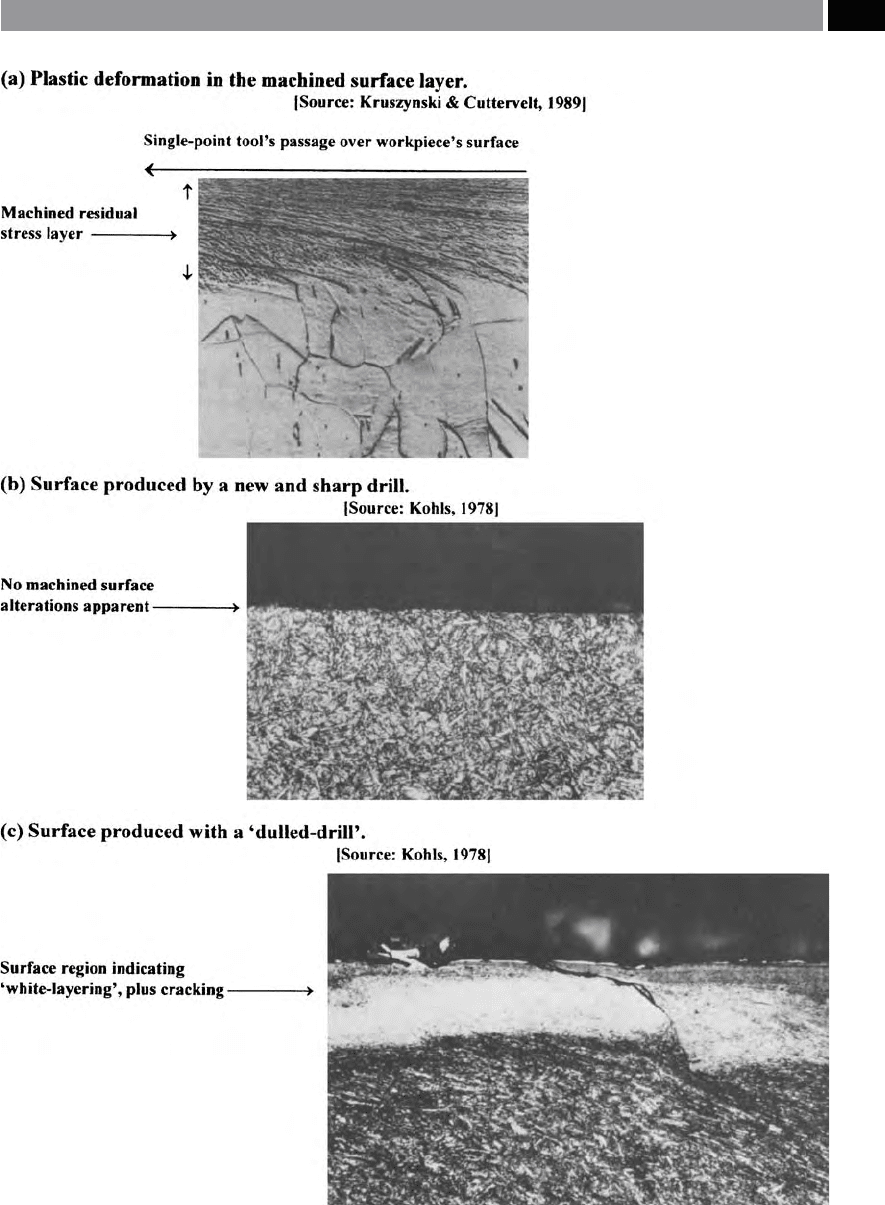
Figure 189. The inuence of the cutting edge’s condition on the resultant machined surface integrity .
Machinability and Surface Integrity 369

In Fig. 189c, a ‘white-layer’ (i.e. for this ferrous
drilled part, being a localised untempered martensitic
phase of 63 H
Rc
91
) exists beneath the recast and rede-
posited layer, in this case produced by a ‘dull’ drill’s
cutting lips and margins. Due to the fact that the recast
layer (i.e. heat-aected zone – HAZ) has a similar met-
a
llurgy to that of the ‘white-layer’ , with the delineation
of these ‘white-layers’ regions and their accompany-
ing HAZ’s are not clearly dened. is latter HAZ is a
complex metallurgical condition, comprising of some:
untempered martensite (UTM); over-tempered mar-
tensite (OTM), while beneath these layers, the bulk
substrate material remains unaected. e thickness
of these ‘white-layer’ zones is strongly inuenced by
both the actual plastic deformation created here and,
to a lesser degree, by the thermal inuence of the pas-
sage of the tool’s edge over the machined surface as
heat penetrates into the locality of the component’s
surface. Probably the worst ‘abusive machining’ condi-
tions that can exist, are when drilling holes in work-
hardening materials having long length-to-diameter
ratios (i.e. L/D ratios of >12:1) with inadequate cool-
ant supply, creating high levels of friction, this condi-
tion being exacerbated by an ineciency produced by
a ‘dulled’ drill’s cutting lips.
Virtually all tooling even the most sharp – the no-
table exception here being monolithic faceted natu-
ral diamond cutting edges, have a nite tip radius of
≈
8 µm (i.e. see Fig. 184 – high-lighting the tool tip
‘rounding eect‘), this results in increased forces and
tool wear, which can transform the surface metallurgy
by thermo-mechanical generation. e case has al-
ready been made concerning the fact that machining
processes impart residual stresses into the surface lay-
ers, as indicated in the schematically-represented mill-
ing conditions shown in Fig. 190 and graphically, in
Fig. 191 for a series of milling operations where preset
‘wear lands’ were generated on the cutter’s teeth prior
to workpiece machining. is latter case (Fig. 191) of
articially-inducing a controlled ‘wear land’ onto the
face-milling cutter’s individual tooth (i.e. with the other
teeth removed, hence, acting as ‘Fly-cutter‘), then aer
91 By way of comparison of this untempered martensitic ‘white-
layer’ phase, a conventional high-speed steel (HSS) milling
cutter’s teeth would have had a maximum hardness aer heat-
treatment of 62 H
Rc
, which clearly signies the true local hard-
ness of these ‘white-layers’.
several milling passes plotting the residual stress levels
from the surface and into the 4340 steel workpiece’s
substrate under standardised cutting data (i.e the steel
specimens having previously been quenched and tem-
pered to a bulk hardness of 52 H
Rc
). Hence, the eect
of these dierent induced tool wear rates and their
inuence in terms of their respective magnitudes and
depths, can clearly be seen. Even when the cutting edge
h
as ‘sharp tooth’ , a certain degree of tensile residual
stress was apparent in the immediate surface region.
Here, directly under this tensile stress zone, the stress
concentration changed to one of compression (i.e. to
a
depth of ≈50 µm). As each milling cutter tooth ank
became steadily more worn, the substrate compression
layer also increased in magnitude, which could lead to
considerable workpiece distortion, once the clamping
forces had been released – particularly if only one-side
of the part was milled (i.e. see Fig. 186b).
If the forces involved in the machining process ex-
ceed the ow stress, plastic deformation occurs and
the structure is deformed. In the case o ductile materi-
als, the plastic ow can create a range of degenerative
surface topography characteristics, such as: burrs; laps;
BUE residue; plus other unwanted debris deposits. If
this deformation becomes severe as a result of exces-
sive plastic ow, any grains adjacent to the surface
may become fragmented to such an extent that little,
or no metallic structure can be metallographically re-
solved, therefore ‘white-layering’ will result. Normally,
a ‘white-layer’ region extends to quite a small depth
b
eneath the surface, in the region of 10 to 100 µm, de-
pending upon the severity of the ‘abusive regime’ of
surface generation. Considering Fig. 191 once again,
as can be seen, the residual stress is indicated along the
vertical axis, here instead, it is alternatively possible
to superimpose a micro-hardness axis – see Fig. 191
circular inset graph. A note of care is required when
changing the vertical axis from residual stress to that
of micro-hardness, as they are two distinct quantita-
tive values. As mentioned the hardness prole closely
approximates that of the residual stress curve, however
in the latter case, instead of tensile stress at the in the
surface region, the sub-surface layer could equally be
compressive in nature.
‘White-layers’ must be avoided under all occasions,
because of the unstable metallurgical condition, com-
pounded by the fact that the these regions act as po-
tential stress-raisers for any critically-engineered com-
ponent and can lead to premature failure, or at worse,
catastrophic failure in-service.
370 Chapter 7
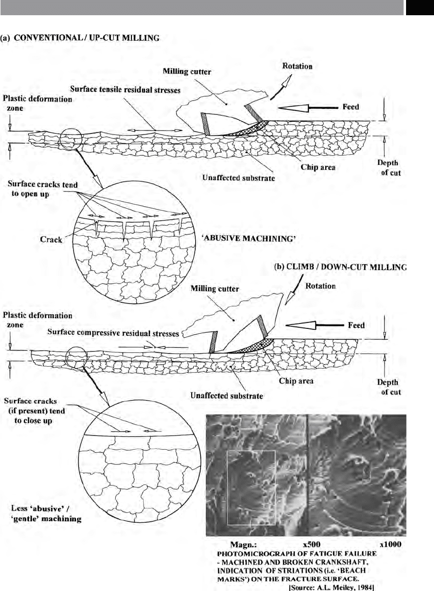
Figure 190. Typical fatigue characteristics within the component’s surface region, being inuenced by the mode of
milling: up-cut or down-cut
.
Machinability and Surface Integrity 371