Smith R., Minton R. Calculus
Подождите немного. Документ загружается.

P1: OSO/OVY P2: OSO/OVY QC: OSO/OVY T1: OSO
MHDQ256-Ch16 MHDQ256-Smith-v1.cls January 7, 2011 11:30
LT (Late Transcendental)
CONFIRMING PAGES
16-21 SECTION 16.3
..
Applications of Second-Order Equations 1093
resulting frequency response curve y = f (ω). Explain why this circuit could be useful
for tuning in a radio station.
Solution We leave it as an exercise to show that the solution of the homogeneous
equation tends to 0 as t increases. The steady-state solution is then the particular
solution u
p
(t) = A sinωt + B cosωt. Here, we have
u
p
(t) = Aω cosωt − Bω sinωt
and u
p
(t) =−Aω
2
sinωt − Bω
2
cosωt.
Substituting into the equation, we have
sinωt = (−Aω
2
sinωt − Bω
2
cosωt) + 8(Aω cos ωt − Bω sinωt)
+2532(A sinωt + B cos ωt)
= [(2532 −ω
2
)A − 8Bω] sinωt + [8Aω +(2532 −ω
2
)B]cos ωt.
Equating the coefficients of the sine and cosine terms gives us the system of equations
(2532 − ω
2
)A − 8ωB = 1
and 8ω A + (2532 −ω
2
)B = 0.
From (3.5), the solution is
A =
2532 − ω
2
(2532 − ω
2
)
2
+ 64ω
2
and B =
−8ω
(2532 − ω
2
)
2
+ 64ω
2
.
Without simplifying this, we can write the steady-state solution as
u
p
(t) = A sinωt + B cosωt as u
p
(t) =
√
A
2
+ B
2
sin(ωt + δ), for some constant δ,so
that the amplitude of the steady-state solution is
√
A
2
+ B
2
. Notice that since A and B
have the same denominator, it factors out of the square root and leaves us with
A
2
+ B
2
=
1
(2532 − ω
2
)
2
+ 64ω
2
(2532 − ω
2
)
2
+ (−8ω)
2
=
1
(2532 − ω
2
)
2
+ 64ω
2
.
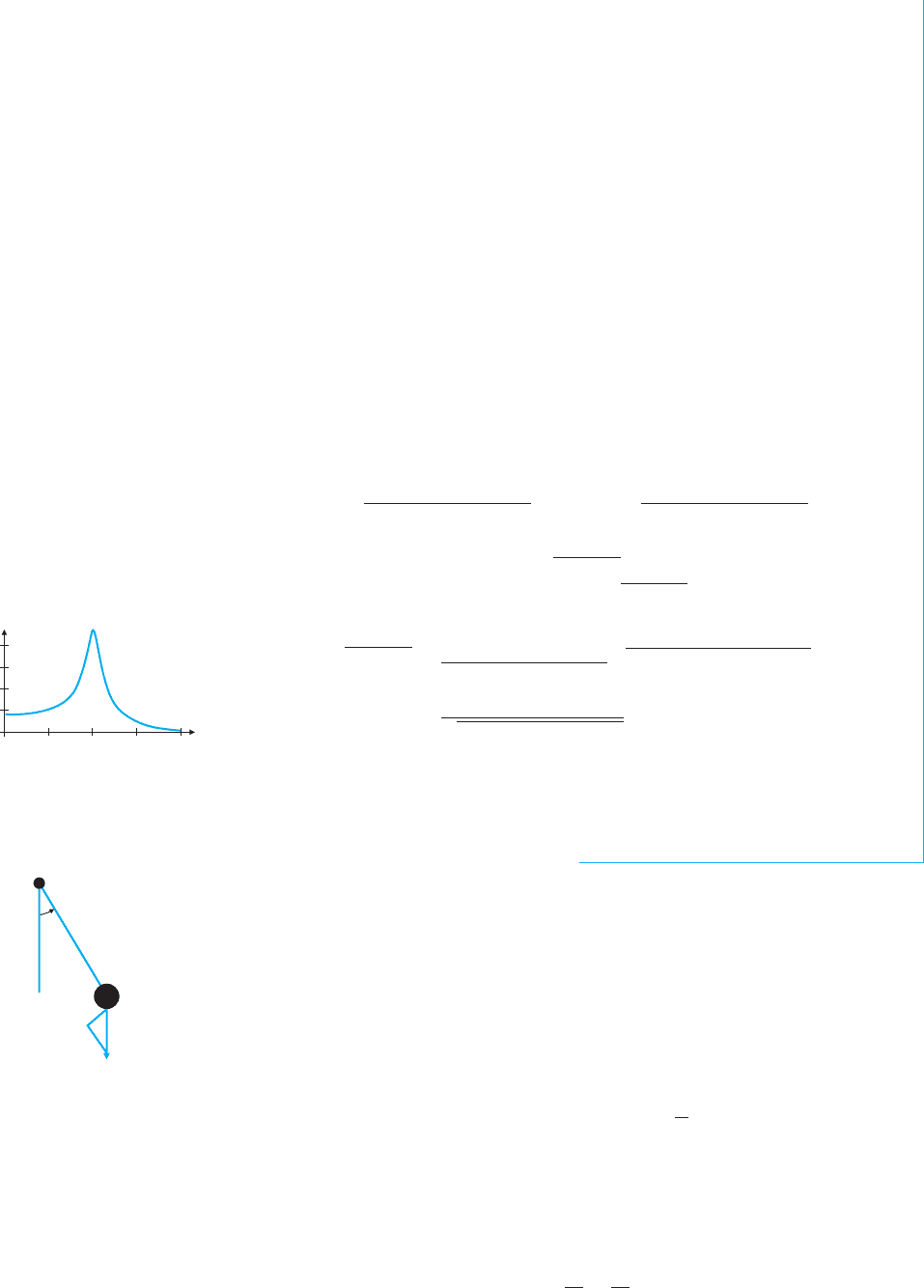
The frequency response curve is the graph of this function, as shown in Figure 16.12.
Notice that the graph has a sharp peak at about ω = 50. Thinking of the right-hand side
of the original equation, sinωt, as a radio signal, we see that this circuit would “hear”
the frequency ω = 50 much better than any other frequency and could thus tune in on a
radio station broadcasting at frequency 50.
ω
y
0.002
0.0005
0.001
0.0015
250 50 75 100
FIGURE 16.12
Frequency response curve y = f (ω)
θ
P
L
mg
m
FIGURE 16.13
A simple pendulum
Another basic physical example with a surprising number of applications is the pendu-
lum. In the sketch in Figure 16.13, a weight of mass m is attached to the end of a massless
rod of length L that rotates about a pivot point P in two dimensions.
We first model the undamped pendulum, where the only force is due to gravity and
the pendulum bob moves along a circular path centered at the pivot point. We can track its
position s on the circle by measuring the angle θ from the vertical, where counterclockwise
is positive. Since s = Lθ, the acceleration is s
= Lθ
. The only forceis gravity, whichhas
magnitude mg in the downward direction. The component of gravity along the direction of
motion is then −mg sinθ . Newton’s second law of motion F = ma gives us
mLθ
(t) =−mg sinθ (t)orθ
(t) +
g
L
sinθ (t) = 0. (3.6)
Notice that (3.6) is not an equation of the form solved in sections 16.1 and 16.2, because
of the term sin θ (t). However, if we simplify (3.6) by replacing sin θ(t)byθ(t), then (3.6)
can be solved quite easily. This replacement is often justified withthe statement. “For small
angles θ,sinθ is approximately equal to θ.” As calculus students, you can say more. From
the Maclaurin series
sinθ = θ −
θ
3
3!
+
θ
5
5!
+···,
P1: OSO/OVY P2: OSO/OVY QC: OSO/OVY T1: OSO
MHDQ256-Ch16 MHDQ256-Smith-v1.cls January 7, 2011 11:30
LT (Late Transcendental)
CONFIRMING PAGES
1094 CHAPTER 16
..
Second-Order Differential Equations 16-22
it follows that the approximation sinθ ≈ θ has an error bounded by |θ|
3
/6. So, if |θ|
3
/6is
small enough to safely neglect, then you can replace (3.6) with
θ
(t) +
g
L
θ(t) = 0. (3.7)
This equation is easy to solve, as we see in example 3.4.
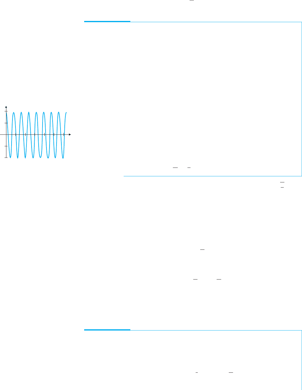
EXAMPLE 3.4 The Undamped Pendulum
A pendulum of length 5 cm satisfies equation (3.7). The bob is released from rest from
a starting angle θ = 0.2. Find an equation for the position at any time t and find the
amplitude and period of the motion.
t
θ
FIGURE 16.14
θ(t) = 0.2 cos 14t
Solution Taking g = 9.8 m/s
2
, we convert the length to L = 0.05 m. Then (3.7)
becomes
θ
(t) +196θ(t) = 0.
The characteristic equation is then r
2
+ 196 = 0, so that r =±14i and the general
solution is
θ(t) = c
1
sin14t + c
2
cos14t,
so that
θ
(t) = 14c
1
cos14t − 14c
2
sin14t.
Since the bob is released from rest, it has no initial velocity and so, the initial conditions
are θ(0) = 0.2 and θ
(0) = 0. From these, we have that 0.2 = θ (0) = c
2
and
0 = θ
(0) = 14c
1
, so that c
1
= 0. The solution is then
θ(t) = 0.2cos 14t,
which has amplitude 0.2 and period
2π
14
=
π
7
. A graph of the solution is shown in
Figure 16.14.
In the exercises, you will show that the period of any solution of (3.7) is 2π
L
g
, which
gives an approximation of the period of the undamped pendulum. Notice that the period is
independent of the mass but depends on the length L.
Observe that the pendulum of example 3.4 oscillates forever. Of course, the motion of
a real pendulum dies out due to damping from friction at the pivot and air resistance. The
simplest model of the force due to damping effects represents the damping as proportional
to the velocity, or kθ
(t) for some constant k. Retaining the approximation sinθ ≈ θ yields
the following model for the damped pendulum:
θ
(t) +kθ
(t) +
g
L
θ(t) = 0,
for some constant k > 0. If we further allow the pendulum to be driven by some external
force F(t), we have the more general model
θ
(t) +kθ
(t) +
g
L
θ(t) =
1
m
F(t). (3.8)
Several areas of current biological research involve situations where one periodic quantity
serves as input into some other system that is naturally periodic. The effect of sunlight on
circadian rhythms and the response of the heart to electrical signals from the sinoatrial node
are examples of this phenomenon. In example 3.5, we explore what happens when a small
amount of damping is present.
EXAMPLE 3.5 A Damped Forced Pendulum
For a pendulum of weight 2 pounds, length 6 inches, damping constant k = 0.1 and
forcing function F(t) = 0.5 sin4t, find the amplitude and period of the steady-state
motion.
Solution Using g = 32ft/s
2
,wehaveL =
1
2
ft and m =
2
32
slug since weight = mg.
Equation (3.8) then becomes
θ
(t) +0.1θ
(t) +64θ(t) = 8sin 4t.
P1: OSO/OVY P2: OSO/OVY QC: OSO/OVY T1: OSO
MHDQ256-Ch16 MHDQ256-Smith-v1.cls January 7, 2011 11:30
LT (Late Transcendental)
CONFIRMING PAGES
16-23 SECTION 16.3
..
Applications of Second-Order Equations 1095
We leave it as an exercise to show that the solution of the homogeneous equation
approaches 0 as t increases. The steady-state solution is then the particular solution
θ
p
(t) = A sin4t + B cos4t.
This gives us
θ
p
(t) = 4A cos4t −4B sin4t
and
θ
p
(t) =−16A sin 4t − 16B cos4t.
Substituting into the differential equation, we have
8sin 4t = (−16A sin4t − 16B cos4t) +0.1(4A cos4t − 4B sin4t)
+64 (A sin4t + B cos4t)
= (48A −0.4B)sin4t +(0.4A +48B)cos4t.
It follows that
48A − 0.4B = 8 and 0.4A + 48B = 0.
The solution of this system is A =
384
2304.16
≈ 0.166655 and B =−
3.2
2304.16
≈−0.001389.
The steady-state solution can now be rewritten as
θ
p
(t) = A sin4t + B cos4t =
A
2
+ B
2
sin(4t +δ) ≈ 0.16666sin(4t −δ),
so that the amplitude is approximately 0.16666 and the period is
2π
4
=
π
2
.
Notice that the period of the steady-state solution in example 3.5 matches the period
of the forcing function 8sin4t and not the natural period of the undamped pendulum,
2π
L
g
=
π
4
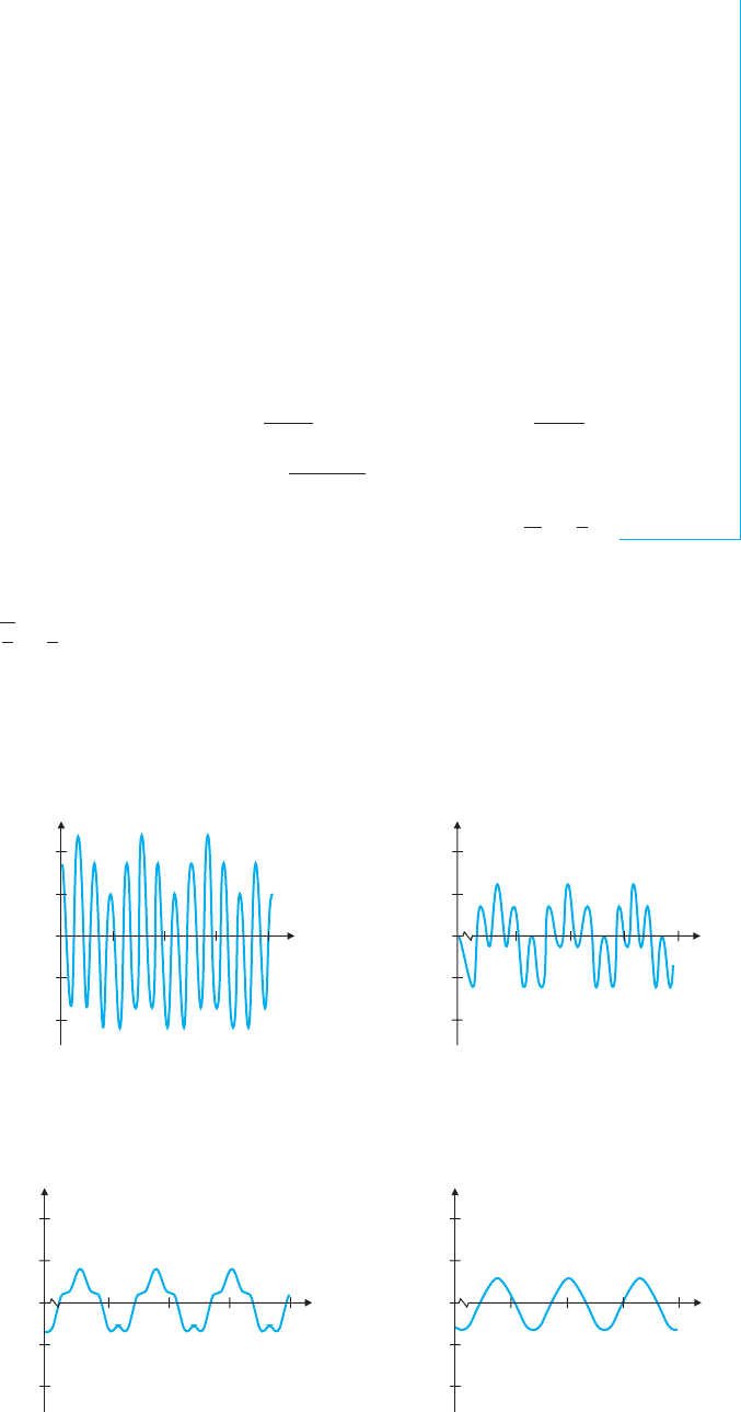
. Keep in mind that the steady-state solution gives the behavior of the solution
for very large t. For small t, the motion of the pendulum in example 3.5 can be erratic.
For initial conditions θ (0) = 0.5 and θ
(0) = 0, the solution for 0 ≤ t ≤ 5 is shown in
Figure 16.15a, while Figures 16.15b–16.15d show the solutions for larger values of t.
Notice that the solution seems to go through different stages until settling down to the
steady-state solution around t = 100.
t
0
0.5
0.25
1.25 2.5 3.75 5
0.25
0.5
θ
t
0
0.5
0.25
21.25 22.5 23.75 2520
0.25
0.5
θ
FIGURE 16.15a FIGURE 16.15b
0 ≤ t ≤ 520≤ t ≤ 25
t
0
0.5
0.25
51.2550 52.5 53.75 55
0.25
0.5
θ
t
0
0.5
0.25
101.25100 102.5 103.75 105
0.25
0.5
θ
FIGURE 16.15c FIGURE 16.15d
50 ≤ t ≤ 55 100 ≤ t ≤ 105

P1: OSO/OVY P2: OSO/OVY QC: OSO/OVY T1: OSO
MHDQ256-Ch16 MHDQ256-Smith-v1.cls January 7, 2011 11:30
LT (Late Transcendental)
CONFIRMING PAGES
1096 CHAPTER 16
..
Second-Order Differential Equations 16-24
EXERCISES 16.3
WRITING EXERCISES
1. The correspondence between mechanical vibrations and elec-
trical circuits is surprising. To start to understand the corre-
spondence, develop an analogy between the roles of a resistor
in a circuit and damping in spring motion. Continue by draw-
ing an analogy between the roles of the spring force and the
capacitor in storing and releasing energy.
2. In example 3.3, explain why the sharper the peak is on
the frequency response curve, the clearer the radio reception
would be.
3. For many objects, the magnitude of air drag is proportional to
the square of the speed of the object. Explain why we would
not want to use that assumption in equation (3.8).
4. To understand why the forced pendulum behaves erratically,
consider the case where a child is on a swing and you push
the swing. If the swing is coming back at you, does your push
increase or decrease the child’s speed? If the swing is moving
forward away from you, does your push increase or decrease
the child’s speed? If you push every three seconds and the
swing is not on a three-second cycle, describe how your push-
ing would affect the movement of the swing.
1. A series circuit has an inductor of 0.4 henry, a resistor of 200
ohms and a capacitor of 10
−4
farad. The initial charge on the
capacitor is 10
−5
coulomb and there is no initial current. Find
the charge on the capacitor and the current at any time t.
2. A series circuit has an inductor of 0.4 henry, no resistance and
a capacitor of 10
−4
farad. The initial charge on the capacitor is
10
−5
coulomb and there is no initial current. Find the charge
on the capacitor and the current at any time t. Find the ampli-
tude and phase shift of the charge function. (See exercise 21 in
section 16.1.)
3. A series circuit has an inductor of 0.2 henry, no resistance and
a capacitor of 10
−5
farad. The initial charge on the capacitor is
10
−6
coulomb and there is no initial current. Find the charge
on the capacitor and the current at any time t. Find the ampli-
tude and phase shift of the charge function. (See exercise 21 in
section 16.1.)
4. A series circuit has an inductor of 0.6 henry, a resistor of 400
ohms and a capacitor of 2 ×10
−4
farad. The initial charge on
the capacitor is 10
−6
coulomb and there is no initial current.
Find the charge on the capacitor and the current at any time t.
5. A series circuit has an inductor of 0.5 henry, a resistor of
2 ohms and a capacitor of 0.05 farad. The initial charge on the
capacitor is zero and the initial current is 1 A. A voltage source
of E(t) = 3 cos 2t volts is analogous to an external force. Find
the charge on the capacitor and the current at any time t.
6. A series circuit has an inductor of 0.2 henry, a resistor of
20 ohms and a capacitor of 0.1 farad. The initial charge on
the capacitor is zero and there is no initial current. A voltage
source of E(t) = 0.4cos4t volts is analogous to an external
force. Find the charge on the capacitor and the current at any
time t.
7. A series circuit has an inductor of 1 henry, a resistor of
10 ohms and a capacitor of 0.5 farad. A voltage source of
E(t) = 0.1cos2t volts is analogous to an external force. Find
the steady-state solution and identify its amplitude and phase
shift. (See exercise 21 in section 16.1.)
8. A series circuit has an inductor of 0.2 henry, a resistor of
40 ohms and a capacitor of 0.05 farad. A voltage source of
E(t) = 0.2 sin 4t volts is analogous to an external force. Find
the steady-state solution and identify its amplitude and phase
shift. (See exercise 21 in section 16.1.)
............................................................
Exercises 9–16 involve frequency response curves and Bode
plots.
9. Suppose that the charge in a circuit satisfies the equation
x
(t) +2x
(t) +5x(t) = A
1
sinωt for constants A
1
and ω.
Find the steady-state solution and rewrite it in the form
A
2
sin(ωt + δ),where A
2
=
A
1
(5 − ω
2
)
2
+ 4ω
2
.Theratio
A
2
A
1
is called the gain of the circuit. Notice that it is independent of
the actual value of A
1
.
10. Graph the gain function g(ω) =
1
(5 − ω
2
)
2
+ 4ω
2
from ex-
ercise 9 as a function of ω>0. This is called a frequency
response curve. Find ω>0 to maximize the gain by mini-
mizing the function f (ω) = (5 −ω
2
)
2
+ 4ω
2
. This value of ω
is called the resonant frequency of the circuit. Also graph the
Bode plot for this circuit, which is the graph of 20log
10
g as
a function of log
10
ω. (In this case, the units of 20log
10
g are
decibels.)
11. The charge in a circuit satisfies the equation
x
(t) +0.4x
(t) +4x(t) = A sin ωt. Find the gain function
and the value of ω>0 that maximizes the gain, and graph the
Bode plot of 20log
10
g as a function of log
10
ω.
12. The charge in a circuit satisfies the equation
x
(t) +0.4x
(t) +5x(t) = A sin ωt. Find the gain function
and the value of ω>0 that maximizes the gain, and graph the
Bode plot of 20log
10
g as a function of log
10
ω.
13. The charge in a circuit satisfies the equation
x
(t) +0.2x
(t) +4x(t) = A sin ωt. Find the gain function
and the value of ω>0 that maximizes the gain, and graph the
Bode plot of 20log
10
g as a function of log
10
ω.
14. Based on your answers to exercises 11–13, which of the con-
stants b, c and A affect the gain in the circuit described by
x
(t) +bx
(t) +cx(t) = A sin ωt?
15. The motion of the arm of a seismometer is modeled by
y
+ by
+ cy = ω
2
cosωt, where the horizontal shift of the
ground during the earthquake is proportional to cos ωt. (See
Multimedia ODE Architect for details.) If b = 1 and c = 4,
find the gain function and the value of ω>0 that maximizes
the gain.
16. The amplitude A of the motion of the seismometer in
exercise 15 andthe distance D ofthe seismometer fromthe epi-
center of the earthquake determine the Richter measurement
M through the formula M = log
10
A +2.56 log
10
D − 1.67.

P1: OSO/OVY P2: OSO/OVY QC: OSO/OVY T1: OSO
MHDQ256-Ch16 MHDQ256-Smith-v1.cls January 7, 2011 11:30
LT (Late Transcendental)
CONFIRMING PAGES
16-25 SECTION 16.3
..
Applications of Second-Order Equations 1097
Use the result of exercise15 to provethat A depends on the fre-
quencyofthe horizontal motion as wellas theactual horizontal
distance moved. Explain in terms of the motion of the ground
during an earthquake why the frequency affects the amount of
damage done.
............................................................
17. In exercise 10, we sketched the Bode plot of the gain as a
function of frequency. The other Bode plot, of phase shift as a
function of frequency, is considered here. First, recall that in
the general relationship a sin ωt + b cosωt = B sin(ωt +θ ),
we have a = B cosθ and b = B sinθ . We can “solve” for θ
as cos
−1
a
B
or sin
−1
b
B
or tan
−1
b
a
. In exercise 10,
we have a =
(5 − ω
2
)A
(5 − ω
2
)
2
+ 4ω
2
and b =
−2ω A
(5 − ω
2
)
2
+ 4ω
2
,so
that B =
√
a
2
+ b
2
=
A
(5 − ω
2
)
2
+ 4ω
2
. For the frequencies
ω>0, this tells us that sin θ<0, so that θ is in quad-
rant III or IV. Explain why the functions sin
−1
b
B
and
tan
−1
b
a
are not convenient for this range of angles. How-
ever, −cos
−1
a
B
gives the correct quadrants. Show that
θ =−cos
−1
5 − ω
2
(5 − ω
2
)
2
+ (2ω)
2
and sketch the Bode
plot.
18. Sketch the plot of phase shift versus frequency for exer-
cise 11.
19. Show that if a, b and c are all positive numbers, then the solu-
tions of ay
+ by
+ cy = 0 approach 0 as t →∞.
20. For the electrical charge equation
LQ
(t) + RQ
(t) +
1
C
Q(t) = 0, if there is nonzero resistance,
what is the eventual charge on the capacitor?
21. Show that the gain in the general circuit described by
ax
(t)+bx
(t)+cx(t)= A sin ωt equals
1
(c −aω
2
)
2
+ (bω)
2
.
22. Showthat in exercise 21 the general resonantfrequency equals
2ac − b
2
2a
2
.
23. A pendulum of length 10 cm satisfies equation (3.7). The bob
is released from a starting angle θ = 0.2. Find an equation for
thepositionatanytime and find theamplitudeandperiodofthe
motion. Compare your solution to that of example 3.4. What
effect does a change in length have?
24. Repeat exercise 23 with a starting angle of θ = 0.4. What ef-
fect does doubling the starting angle have?
25. A pendulum of length 10 cm satisfies equation (3.7). The
bob is released from a starting angle θ = 0 with an initial
angular velocity of θ
= 0.1. Find an equation for the po-
sition at any time and find the amplitude and period of the
motion.
26. Repeat exercise 25 with initial angular velocity θ
= 0.2. What
effect does doubling the initial angular velocity have?
27. For a pendulum of weight 6 pounds, length 8 inches, damping
constant k = 0.2 and forcing function F(t) = cos3t, find the
amplitude and period of the steady-state motion.
28. For a pendulum of weight 6 pounds, length 8 inches, damp-
ing constant k = 0.2 and forcing function F(t) = cos6t, find
the amplitude and period of the steady-state motion. Compare
your solution to that of exercise 27. Does the frequency of the
forcing function affect the amplitude of the motion?
29. In example 3.3, find the general homogeneous solution and
show that it approaches 0 as t →∞.
30. In example 3.5, find the general homogeneous solution and
show that it approaches 0 as t →∞.
31. Use Taylor’s Theorem to prove that the error in the approxi-
mation sinθ ≈ θ is bounded by |θ|
3
/6.
32. Tokeepthe errorin the approximation sin θ ≈ θ less than 0.01,
how small does θ need to be?
APPLICATIONS
33. Show that the solution of θ
+
g
L
θ = 0 has period 2π
L
g
.
Galileo deduced that the square of the period varies directly
with the length. Is this consistent with a period of 2π
L
g
?
34. Galileo believed that the period of a pendulum is independent
of the weight of the bob. Determine whether the model (3.7) is
consistent with this prediction.
35. Galileo further believed that the period of a pendulum is inde-
pendent of its amplitude. Use exercise24to determine whether
the model (3.7) supports this conjecture.
36. Taking into account damping, Galileo found that a pendulum
will eventually come to rest, with lighter ones coming to rest
fasterthan heavyones. Showthat this is implied by (3.8) in that
forpendulumsof identical length anddampingconstant c (note
that c is different from k) but different masses, the pendulum
with the smaller mass will come to rest faster.
37. The gun of a tank is attached to a system with springs and
dampers such that the displacement y(t) of the gun after being
fired at time 0 is
y
+ 2αy
+ α
2
y = 0,
for some constant α. Initial conditions are y(0) = 0 and
y
(0) = 100. Estimate α such that the quantity y
2
+ (y
)
2
is
less than 0.01 at t = 1. This enables the gun to be fired again
rapidly.
38. LetG(t)betheconcentrationofglucoseinthebloodstreamand
g(t) = G(t) − G
0
thedifferencebetweenthe glucoseleveland
the ideal concentration G
0
. Braun derives an equation of the
form
g
(t) +2αg
(t) +ω
2
g(t) = 0
for the concentration t hours after a glucose injection. It
turns out that if the natural period
2π
ω
of the solution is less
than 4 hours, the patient is not likely to be diabetic, whereas
2π
ω
> 4 is an indicator of mild diabetes. Using α = 1 and ini-
tial conditions g(0) = 10 and g
(0) = 0, compare the graphs of

P1: OSO/OVY P2: OSO/OVY QC: OSO/OVY T1: OSO
MHDQ256-Ch16 MHDQ256-Smith-v1.cls January 7, 2011 11:30
LT (Late Transcendental)
CONFIRMING PAGES
1098 CHAPTER 16
..
Second-Order Differential Equations 16-26
glucose levels for a healthy patient with ω = 2 and a diabetic
patient with ω = 1.
39. If 0 <α<ω,showthatthesolutioninexercise38 is adamped
exponential.Showthatthetimebetweenzerosofthe solutionis
greaterthan
π
ω
.Use thisresulttodeterminewhetherthefollow-
ingpatientwouldbesuspectedofdiabetes.Theoptimalglucose
level is 75 mg glucose/100 ml blood. The glucose levels are
90 mg glucose/100 ml blood one hour after an injection, 70 mg
glucose/100 ml blood two hours after the injection and 78 mg
glucose/100 ml blood three hours after the injection.
40. Showthat the data in exercise 39 are inconsistent with the case
0 <ω<α.
41. Consider an RLC-circuit with capacitance C and charge Q(t)
at time t. The energy in the circuit at time t is given by
u(t) =
[Q(t)]
2
2C
. Show that the charge in a general RLC-circuit
has the form
Q(t) = e
−(R/L)t/2
|Q
0
cosωt + c
2
sinωt|,
where Q
0
= Q(0) and ω =
1
2L
R
2
− 4L/C. The relative
energy loss from time t = 0 to time t =
2π
ω
is given by
U
loss
=
u(2π/ω) − u(0)
u(0)
and the inductance quality factor
is defined by
2π
U
loss
. Using a Taylor polynomial approximation
of e
x
, show that the inductance quality factor is approximately
ω
L
R
.
EXPLORATORY EXERCISES
1. In quantum mechanics, the possible locations of a particle are
described by its wave function (x). The wave function sat-
isfies Schr¨odinger’s wave equation
¯h
2m
(x) + V (x)(x) = E(x).
Here, ¯h is Planck’s constant, m is mass, V (x) is the potential
function for external forces and E is the particle’s energy. In
the case of a bound particle with an infinite square well of
width 2a, the potential function is V (x) = 0 for −a ≤ x ≤ a.
We will show that the particle’s energy is quantized by solv-
ing the boundary value problem consisting of the differential
equation
¯h
2m
(x) + v(x)(x) = E(x) plus the boundary
conditions (−a) = 0 and (a) = 0. The theory of bound-
ary value problems is different from that of the initial value
problemsinthischapter,whichtypicallyhaveuniquesolutions.
In fact, in this exercise we specifically want more than one so-
lution. Start with the differential equation and show that for
V(x) = 0; the general solution is (x) = c
1
coskx +c
2
sinkx,
where k =
√
2mE/ ¯h. Then set up the equations (−a) = 0
and (a) = 0. Both equations are true if c
1
= c
2
= 0, but in
this case the solution would be (x) = 0. To find nontrivial
solutions (that is, nonzero solutions), find all values of k such
that coska = 0 or sin ka = 0. Then, solve for the energy E in
terms of a, m and ¯h. These are the onlyallowableenergy levels
for the particle. Finally, determine what happens to the energy
levels as a increases without bound.
2. Imagine a hole drilled through the center of the Earth. What
would happen to a ball dropped in the hole? Galileo conjec-
tured that the ball would undergo simple harmonic motion,
which is the periodic motion of an undamped spring or pendu-
lum. This solution requires no friction and a nonrotating Earth.
Theforce due to gravityoftwo objects r units apart is
Gm
1
m
2
r
2
,
where G is the universal gravitation constant and m
1
and m
2
are the masses of the objects. Let R be the radius of the Earth
and y the displacement from the center of the Earth.
y
R
0
For a ball at position y with |y|≤R, the ball is attracted to the
center of the Earth as if the Earth were a single particle located
at the origin with mass ρv, where ρ is the density of the Earth
and v is the volume of the sphere of radius|y|. (This assumes a
constant density and a spherical Earth.) If M is the mass of the
Earth,showthat ifyou neglectdamping, the positionof the ball
satisfies the equation y
+
GM
R
3
y = 0. Use g =
GM
R
2
to sim-
plify this. Find the motion of the ball. Does the period depend
on the starting position? Compare the motions of balls dropped
simultaneouslyfromtheEarth’ssurfaceandhalfwaytothecen-
ter of the Earth. Explore the motion of a ball thrown from the
surface of the Earth at y = R with initial velocity −R/100.
16.4 POWER SERIES SOLUTIONS OF DIFFERENTIAL EQUATIONS
So far in this chapter, we have seen how to solve only those second-order equations with
constant coefficients, such as
y
− 6y
+ 9y = 0.
What if the coefficients aren’t constant? For instance, suppose you wanted to solve the
equation
y
+ 2xy
+ 2y = 0.

P1: OSO/OVY P2: OSO/OVY QC: OSO/OVY T1: OSO
MHDQ256-Ch16 MHDQ256-Smith-v1.cls January 7, 2011 11:30
LT (Late Transcendental)
CONFIRMING PAGES
16-27 SECTION 16.4
..
Power Series Solutions of Differential Equations 1099
We leave it as an exercise to show that substituting y = e
rx
in this case does not lead to a
solution. However, in many cases such as this, we can find a solution by assuming that the
solution can be written as a power series, such as
y =
∞
n=0
a
n
x
n
.
The idea is to substitute this series into the differential equation and then use the resulting
equation to determine the coefficients, a
0
, a
1
, a
2
...,a
n
,....Before we see how to do this
in general, we illustrate this for a simple equation whose solution is already known, to
demonstrate that we arrive at the same solution using either method.
EXAMPLE 4.1 Power Series Solution of a Differential Equation
Use a power series to determine the general solution of
y
+ y = 0.
Solution First, observe that this equation has constant coefficients and its general
solution is
y = c
1
sin x + c
2
cos x,
where c
1
and c
2
are constants.
We now look for a solution of the equation in the form of the power series
y = a
0
+ a
1
x +a
2
x
2
+ a
3
x
3
+···=
∞
n=0
a
n
x
n
.
To substitute this into the equation, we first need to obtain representations for y
and y
.
Assuming that the power series is convergent and has a positive radius of convergence,
recall that we can differentiate term-by-term to obtain the derivatives
y
= a
1
+ 2a
2
x +3a
3
x
2
+···=
∞
n=1
na
n
x
n−1
and
y
= 2a
2
+ 6a
3
x +···=
∞
n=2
n(n −1)a
n
x
n−2
.
Substituting these power series into the differential equation, we get
0 = y
+ y =
∞
n=2
n(n −1)a
n
x
n−2
+
∞
n=0
a
n
x
n
. (4.1)
REMARK 4.1
Notice that when we change
∞
n=2
n(n − 1)a
n
x
n−2
to
∞
n=0
(n + 2)(n + 1)a
n+2
x
n
, the
index in the sequence increases
by 2 (for example, a
n
becomes
a
n+2
), while the initial value of
the index decreases by 2.
The immediate objective here is to combine the two series in (4.1) into one power
series. Since the powers in the one series are of the form x
n−2
and in the other series
are of the form x
n
, we will first need to rewrite one of the two series. Notice that we
have
y
=
∞
n=2
n(n −1)a
n
x
n−2
= 2a
2
+ 3 ·2a
3
x +4 ·3a
4
x
2
+···
=
∞
n=0
(n + 2)(n + 1)a
n+2
x
n
.
Substituting this into equation (4.1) gives us
0 = y
+ y =
∞
n=0
(n + 2)(n + 1)a
n+2
x
n
+
∞
n=0
a
n
x
n
=
∞
n=0
[(n + 2)(n + 1)a
n+2
+ a
n
]x
n
. (4.2)

P1: OSO/OVY P2: OSO/OVY QC: OSO/OVY T1: OSO
MHDQ256-Ch16 MHDQ256-Smith-v1.cls January 7, 2011 11:30
LT (Late Transcendental)
CONFIRMING PAGES
1100 CHAPTER 16
..
Second-Order Differential Equations 16-28
Read equation (4.2) carefully; it says that the power series on the right converges to
theconstant function f (x) = 0.Inviewof this, allofthe coefficientsmustbe zero. Thatis,
0 = (n + 2)(n + 1)a
n+2
+ a
n
,
for n = 0, 1, 2,.... We solve this for the coefficient with the largest index, to obtain
a
n+2
=
−a
n
(n + 2)(n + 1)
, (4.3)
for n = 0, 1, 2,....Equation (4.3) is called the recurrence relation, which we use to
determine all of the coefficients of the series solution. The general idea is to write out
(4.3) for a number of specific values of n and then try to recognize a pattern that the
coefficients follow. From (4.3), we have for the even-indexed coefficients that
a
2
=
−a
0
2 · 1
=
−1
2!
a
0
,
a
4
=
−a
2
4 · 3
=
1
4 · 3 · 2 · 1
a
0
=
1
4!
a
0
,
a
6
=
−a
4
6 · 5
=
−1
6!
a
0
,
a
8
=
−a
6
8 · 7
=
1
8!
a
0
and so on. (Try to write down a
10
by recognizing the pattern, without referring to the
recurrence relation.) Since we can write each even-indexed coefficient as a
2n
, for some
n, we can now write down a simple formula that works for any of these coefficients.
We have
a
2n
=
(−1)
n
(2n)!
a
0
,
for n = 0, 1, 2,....Similarly, using (4.3), we have that the odd-indexed coefficients are
a
3
=
−a
1
3 · 2
=
−1
3!
a
1
,
a
5
=
−a
3
5 · 4
=
1
5!
a
1
,
a
7
=
−a
5
7 · 6
=
−1
7!
a
1
,
a
9
=
−a
7
9 · 8
=
1
9!
a
1
and so on. Since we can write each odd-indexed coefficient as a
2n+1
(or alternatively as
a
2n−1
), for some n, note that we have the following simple formula for the odd-indexed
coefficients:
a
2n+1
=
(−1)
n
(2n + 1)!
a
1
,
for n = 0, 1, 2,....Since we have now written every coefficient in terms of either a
0
or
a
1
, we can rewrite the solution by separating the a
0
terms from the a
1
terms. We have
y =
∞
n=0
a
n
x
n
= a
0
+ a
1
x +a
2
x
2
+ a
3
x
3
+···
= a
0
1 −
1
2!
x
2
+
1
4!
x
4
+···
+ a
1
x −
1
3!
x
3
+
1
5!
x
5
+···
= a
0
∞
n=0
(−1)
n
(2n)!
x
2n
y
1
(x)
+ a
1
∞
n=0
(−1)
n
(2n + 1)!
x
2n+1
y
2
(x)
= a
0
y
1
(x) +a
1
y
2
(x), (4.4)

P1: OSO/OVY P2: OSO/OVY QC: OSO/OVY T1: OSO
MHDQ256-Ch16 MHDQ256-Smith-v1.cls January 7, 2011 11:30
LT (Late Transcendental)
CONFIRMING PAGES
16-29 SECTION 16.4
..
Power Series Solutions of Differential Equations 1101
where y
1
(x) and y
2
(x) are two solutions of the differential equation (assuming the series
converge). At this point, you should be able to easily check that both of the indicated
power series converge absolutely for all x, by using the Ratio Test. Beyond this, you
might also recognize that the series solutions y
1
(x) and y
2
(x) that we obtained are, in
fact, the Maclaurin series expansions of cosx and sin x, respectively. In light of this,
(4.4) is an equivalent solution to that found by using the methods of section 16.1.
The method used to solve the differential equation in example 4.1 is certainly far
more complicated than the methods we used in section 16.1 for solving the same equation.
However, this new method can be used to solve a wider range of differential equations than
those solvable using our earlier methods. We now return to the equation mentioned in the
introduction to this section.
EXAMPLE 4.2 Solving a Differential Equation with Variable Coefficients
Find the general solution of the differential equation
y
+ 2xy
+ 2y = 0.
Solution First, observe that since the coefficient of y
is not constant, we have little
choice but to look for a series solution of the equation. As in example 4.1, we begin by
assuming that we may write the solution as a power series,
y =
∞
n=0
a
n
x
n
.
As before, we have
y
=
∞
n=1
na
n
x
n−1
and
y
=
∞
n=2
n(n −1)a
n
x
n−2
.
Substituting these three power series into the equation, we get
0 = y
+ 2xy
+ 2y =
∞
n=2
n(n −1)a
n
x
n−2
+ 2x
∞
n=1
na
n
x
n−1
+ 2
∞
n=0
a
n
x
n
=
∞
n=2
n(n −1)a
n
x
n−2
+
∞
n=1
2na
n
x
n
+
∞
n=0
2a
n
x
n
, (4.5)
where in the middle term, we moved the x into the series and combined powers of x.In
order to combine the three series, we must only rewrite the first series so that its general
term is a multiple of x
n
, instead of x
n−2
. As we did in example 4.1, we write
∞
n=2
n(n −1)a
n
x
n−2
=
∞
n=0
(n + 2)(n + 1)a
n+2
x
n
and so, from (4.5), we have
0 =
∞
n=2
n(n −1)a
n
x
n−2
+
∞
n=1
2na
n
x
n
+
∞
n=0
2a
n
x
n
=
∞
n=0
(n + 2)(n + 1)a
n+2
x
n
+
∞
n=0
2na
n
x
n
+
∞
n=0
2a
n
x
n
=
∞
n=0
[(n + 2)(n + 1)a
n+2
+ 2na
n
+ 2a
n
]x
n
=
∞
n=0
[(n + 2)(n + 1)a
n+2
+ 2(n + 1)a
n
]x
n
. (4.6)

P1: OSO/OVY P2: OSO/OVY QC: OSO/OVY T1: OSO
MHDQ256-Ch16 MHDQ256-Smith-v1.cls January 7, 2011 11:30
LT (Late Transcendental)
CONFIRMING PAGES
1102 CHAPTER 16
..
Second-Order Differential Equations 16-30
To get this, we used the fact that
∞
n=1
2na
n
x
n
=
∞
n=0
2na
n
x
n
. (Notice that the first term in
the series on the right is zero!) Reading equation (4.6) carefully, note that we again have
a power series converging to the zero function, from which it follows that all of the
coefficients must be zero:
0 = (n + 2)(n + 1)a
n+2
+ 2(n + 1)a
n
,
for n = 0, 1, 2,.... Again solving for the coefficient with the largest index, we get the
recurrence relation
a
n+2
=−
2(n + 1)a
n
(n + 2)(n + 1)
or
a
n+2
=−
2a
n
n + 2
.
REMARK 4.2
Always solve for the coefficient
with the largest index.
Much like we saw in example 4.1, the recurrence relation tells us that all of the
even-indexed coefficients are related to a
0
, while all of the odd-indexed coefficients are
related to a
1
. In order to try to recognize the pattern, we write out a number of terms,
using the recurrence relation. We have
a
2
=−
2
2
a
0
=−a
0
,
a
4
=−
2
4
a
2
=
1
2
a
0
,
a
6
=−
2
6
a
4
=−
1
3!
a
0
,
a
8
=−
2
8
a
6
=
1
4!
a
0
and so on. At this point, you should recognize the pattern for these coefficients. (If not,
write out a few more terms.) Note that we can write the even-indexed coefficients as
a
2n
=
(−1)
n
n!
a
0
,
for n = 0, 1, 2,.... Be sure to match this formula against those coefficients calculated
above to see that they match. Continuing with the odd-indexed coefficients, we have
from the recurrence relation that
a
3
=−
2
3
a
1
,
a
5
=−
2
5
a
3
=
2
2
5 · 3
a
1
,
a
7
=−
2
7
a
5
=−
2
3
7 · 5 · 3
a
1
,
a
9
=−
2
9
a
7
=
2
4
9 · 7 · 5 · 3
a
1
and so on. While you might recognize the pattern here, it’s hard to write down this
pattern succinctly. Observe that the products in the denominators are not quite
factorials. Rather, each is the product of the first so many odd numbers. The solution to
this is to write this as a factorial, but then cancel out all of the even integers in the
product. In particular, note that
1
9 · 7 · 5 · 3
=
2·4
8 ·
2·3
6 ·
2·2
4 ·
2·1
2
9!
=
2
4
· 4!
9!
,
so that a
9
becomes
a
9
=
2
4
9 · 7 · 5 · 3
a
1
=
2
4
· 2
4
· 4!
9!
a
1
=
2
2·4
· 4!
9!
a
1
.