Tsoulos George (ред.) MIMO System Technology for Wireless Communications
Подождите немного. Документ загружается.


274 MIMO System Technology for Wireless Communications
10.1 Introduction
For some time researchers around the world have developed testbeds to
further
experimental wireless communications research. The work on multi-
antenna systems was initiated at UCLA in 1998 with the high-speed QAM
testbed, which incorporated smart antenna processing to deliver 30 Mbps
in a 5 MHz band [1]. The MIMO narrowband testbed described in [2] was
the first MIMO testbed reported in the literature. This was followed by a
fast frequency hopping spread spectrum testbed in 2001 [3] and, finally, two
broadband MIMO-OFDM testbeds were recently completed [4,32].
The investment of time, money, and resources required to see a testbed
development through is enormous, and it often confronts research teams
with the following questions:
• Why is a testbed needed and how can the associated expenditure of
time, money, and resources be justified?
• Should it support real-time or non-real-time operation?
• What elements and components are needed to make the testbed and
the ensuing research successful?
Perhaps the first question is the most important one to answer. Invariably,
in any organization, one finds the “simulation-only” camp that advocates a
simulation-only approach to system development. In the past, many semi-
conductor vendors have gone straight to silicon after exhaustive simulations
and have had successful products. So is a testbed really necessary? The answer
resides in the maturity of the technology, market, and communication par-
adigms that one faces. If the characteristics of a medium are well understood,
or the worst-case channel conditions are specified in a standard, and the
imperfections of the analog circuits have been thoroughly documented, then
a simulation-only approach will suffice. This might be the case for traditional
wireline communications or even narrowband cellular communications.
However, it is most certainly not the case with MIMO systems, which are
ushering in a paradigm shift in wireless data communications, namely the
exploitation of the spatial dimension in addition to time and frequency for
the transmission of signals.
More generally, our experience has shown that a testbed is justified if one
or more of the following conditions are met:
• There is no accurate model of the channel.
• The RF impairments are not known, or if they are known, their
impact on the performance of the wireless link is ambiguous.
• Long-term behavior (continuous operation over many hours) of the
algorithms and/or hardware are not known.
• Accurate modeling of the interference seen by the unit due to net-
worked operation is unknown.
4190_book.fm Page 274 Tuesday, February 21, 2006 9:14 AM
Multi-Antenna Testbeds for Wireless Communications
275
Given the current state of research and commercial activity in the area of
MIMO communication systems, it is safely stated that all of the above four
conditions are met, either in part or in full. Channel models exist, but are
rudimentary and do not properly model the angle of arrival of the rays and
the correlation between signals coming into each receive antenna. The RF
impairments are not new for MIMO systems; however, the magnitude of
their impact on the underlying performance of the system is not known. For
example, the impact of an imbalance between the in-phase and quadrature
rails (I/Q Imbalance) in RF architectures with zero-IF is substantially more
detrimental in MIMO than in traditional SISO systems. Similarly, the effect
of any coupling of signals from different RF chains on the resulting perfor-
mance is unknown. The decoding algorithms needed for MIMO systems are
also new and untested for long-term operation. Drifts of adaptive algorithms
due to fixed precision implementation and/or bounds on performance for
long-lasting links are all unknown. Finally, the performance of MIMO-
enabled nodes in the presence of random network interference is unknown.
All of this helps motivate and justify testbed development and experimental
research in the area of multi-antenna systems.
This chapter provides insight into the development process of wireless
communications testbeds, starting with the classification of testbeds to
deployment and field measurements with them. To serve as examples, three
particular testbeds, all MIMO, will often be referred to. The first one is a
mature, narrowband, DSP-based system. It operates in real-time with 4 kHz
of bandwidth in the 220 MHz frequency band. A few interesting test setups
include 3 ×
4 MIMO system, infrastructure-based networking with multi-
antenna support at the base station, and ad-hoc networking with multiple
mobile radios. The other two testbeds are both broadband MIMO-OFDM
systems, built by two different research groups with entirely different
research goals. For this reason, the testbed’s architectures are also funda-
mentally different. One team focuses on the design of high-performance
digital VLSI circuits for broadband wireless communications. Accordingly,
their testbed’s RF section was implemented with a zero-IF architecture for
a carrier frequency at 5.25 GHz and a bandwidth of 25 MHz. That choice
revealed the problem of I/Q imbalance in MIMO systems, opening up a rich
field for applied research that produced valuable new knowledge. The
results from that testbed shown here correspond to measurements taken
when the testbed had 2 ×
2 capabilities with non-real-time baseband pro-
cessing. The other group’s research is motivated by the goal of furthering
fundamental understanding of MIMO communications. Their testbed is,
therefore, an instrument for closing the loop of the scientific method through
actual field experiments and channel sounding. It operates with a bandwidth
of 20 MHz at a carrier frequency of 2.4 GHz. The baseband signals are
digitally up and down-converted from to an IF at 70 MHz.
This chapter is organized as follows. Section 10.2 provides a discussion of
testbed classifications, followed by the identification of the necessary ele-
ments for developing a successful testbed in Section 10.3. Section 10.4 is
4190_book.fm Page 275 Tuesday, February 21, 2006 9:14 AM

276 MIMO System Technology for Wireless Communications
devoted to lessons learned in the course of developing and calibrating the
aforementioned multi-antenna testbeds. Automation of field measurement
procedures is treated in Section 10.5, and Section 10.6 provides a summary
of the results obtained using three different MIMO testbeds.
10.2 Testbed Classification
The design and development of a testbed is guided by a number of param-
eters derived from the specific research goal and available funding. While
the research goal itself may range from plain Bit Error Rate (BER) measure-
ments to entire networking experiments, other parameters such as desired
throughput, form factor, configurability, testbed mobility, development time,
and cost are equally relevant. As a whole, all these aspects are tightly coupled
with two fundamental properties of a testbed, namely:
1. The technology of choice for implementing the testbed’s baseband
processing engine
2. Whether the testbed can operate in real-time or not, i.e., whether the
processing power at baseband is required to match the throughput
of the testbed’s RF section or not
The above two qualities are, of course, not independent of each other: they
are coupled through the bandwidth (or throughput) of the system. The
situation is shown in Figure 10.1.
Considering the above two categories, perhaps the simplest type of testbed
is a software-based, non-real-time system. This approach is often used as a
FIGURE 10.1
Real-time operation of a testbed as a function of system bandwidth and baseband processing
technology. The boundary between real-time and non-real-time operation moves right as the
technology of integrated circuits progresses.
ASIC
FPGA
DSP
SW
Real-time
Bandwidth
Non-real-time
4190_book.fm Page 276 Tuesday, February 21, 2006 9:14 AM

Multi-Antenna Testbeds for Wireless Communications
277
starting point in the implementation of more hardware intensive and/or
real-time testbeds, although it may serve as a final goal as well. It typically
involves designing and fabricating (or purchasing) the RF front-end mod-
ules, plus buffering interfaces and a software-based, PC-hosted baseband
processing engine wrapped around them. Overall, such a system has a short
development time and low cost.
Although unable to provide real-time functionality, a software-based for-
mulation is very valuable during the initial phase of development because
it provides great flexibility for configuring and blueprinting a more complex
platform. For instance, it allows for developing the transmission format (e.g.,
a packet structure) that best fits the research goals, and for testing algorithms
for synchronization, channel estimation, equalization, etc. These software
tools also serve as an important reference point for calibrating fixed-precision
implementations in a later stage of development.
This kind of testbed is not a “one-box” solution; they are difficult to
transport for demonstration purposes and do not lend themselves well to
experiments with mobility, although it is possible to use them for collecting
BER statistics in stationary conditions, while measuring packet or network-
level performance would be cumbersome and slow.
When real-time operation is necessary (e.g., for communications with feed-
back), several options are available depending on the targeted bandwidth
and desired throughput of the system. If it is relatively low, then real-time
implementations are feasible at low cost with commercially available pro-
grammable Digital Signal Processors (DSPs), which replace the PCs and
memory boards of the software-based testbed described earlier. On the other
hand, when sustained high throughput is required, dedicated Field Program-
mable Gate Array (FPGA)-based solutions, and even developing Applica-
tion-Specific Integrated Circuits (ASICs) become appropriate — the latter at
much increased cost (Table 10.1).
A DSP-based, real-time system requires significantly less development
time than an FPGA or ASIC-based solution (Table 10.1). Its capability enables
one to collect performance statistics at a packet level and over extended
periods of time, making it well suited for networking experiments. In addi-
tion, the real-time nature of this kind of testbed allows for the system to be
used as a simulation accelerator.
Dedicated ASICs take time to design and are not reconfigurable, and even
though FPGAs provide the flexibility, the hardware design process itself can
be time-consuming. Nevertheless, these alternatives have a small form factor
TABLE 10.1
Cost and Development Time for Various Baseband
Processing Technologies
SW DSP FPGA ASIC
Hardware Cost Low Low-Medium Low-Medium High
Development Time Short Medium Medium-Long Long
4190_book.fm Page 277 Tuesday, February 21, 2006 9:14 AM

278 MIMO System Technology for Wireless Communications
and are ideal for field trials that involve mobility and networking experi-
ments. ASICs for communication applications also provide graduate level
research opportunities in a variety of topics involving efficient signal pro-
cessing architectures for VLSI implementation.
10.3 Elements of a Successful Testbed
A testbed has a progressively greater chance for success as it increasingly
captures the following five characteristics:
1. The testbed is thoroughly calibrated,
2. The testbed interfaces easily to a realistic simulation or emulation
platform,
3. The testbed is easily and quickly configurable,
4. The testbed has mechanisms to highly automate field testing,
5. The testbed reflects design tradeoffs that will be present in the final
system implementation.
These five characteristics ensure that the testbed experience is fruitful and
efficient. Much of the work in a testbed development is spent explaining
experimental data that behave in unexpected ways. Most often (in the
authors’ experience) the unusual behavior is a function of the experimental
hardware used in the testbed, while less often the unusual behavior is due
to interesting characteristics of wireless propagation and communication
algorithms. The above five characteristics allow the engineering team to
quickly isolate the source of the unusual behavior and quickly address the
issue by (1) attempting to change the experimental hardware or (2) collecting
enough data to write a paper of archival quality on the unusual characteristic.
The remainder of this section will highlight the important aspects of the five
elements of a successful testbed.
Calibration
: Thorough quantification of the testbed’s performance is essen-
tial for understanding the experimental results. Testbed development should
only be attempted by teams that are willing to engage in a slow, methodical
development effort. The best approach is to have integration of the testbed
take place by slowly adding in components of the testbed and completely
calibrating the performance. As a minimum, it is important to integrate a
communication system (1) at the baseband algorithm level, (2) at the base-
band plus radios in a cabled environment, (3) with a full system using
channel emulation, and finally (4) a full over the air
system. The testbed
must be calibrated at each step of the way and compared to any theoretical
performance bounds that might be available. In a testbed development there
will be performance anomalies, hardware issues, and component failures.
4190_book.fm Page 278 Tuesday, February 21, 2006 9:14 AM
Multi-Antenna Testbeds for Wireless Communications
279
These issues will be much easier to debug if calibration has been completed
and documented in a variety of configurations. In addition, the calibration
often makes it apparent that hardware imperfections need to be compensated
to achieve the desired performance. The sequel will discuss several of these
hardware imperfections, e.g., I/Q imbalances and phase noise, and how
compensation was implemented to get better performance in the testbed.
Interfacing easily to a realistic simulation or emulation platform
: Having an
associated emulation and simulation facility for the testbed allows one to
hypothesize about performance characteristics and troubleshoot system
issues. A critical aspect of a testbed development is the ability to model
performance anomalies in a controlled simulation environment. A testbed
radio system is an imperfect system, and some of these imperfections can
cause noticeable degradations. Having a simulation and emulation system
enables the development team to discern which characteristics are important
and which are not.
Configurability
: Being able to rapidly and reliably configure the testbed
produces a system that is more useful in experimental research. The primary
(and perhaps only) users of a testbed are its developers. They spend time
developing applications, troubleshooting, running calibration tests, running
field tests, and doing demonstrations. Similarly, all of the work to be done
on the testbed for both development and testing will require compiling and
running software (C or DSP code) or firmware (embedded software or FPGA
code) on the target system on a frequent basis. Each of these uses of the
testbed is greatly facilitated by having the testbed configuration automated,
remotely controlled and by having initialization scripts centralizing the def-
inition of all the important parameters in one configuration file.
A major use of the testbed is also in marketing the research. People tend
to understand and appreciate work to a much greater degree when it can
be seen in action, so being able to quickly and efficiently prepare a demon-
stration of a testbed is a very important aspect of making it successful.
Automated test mechanics
: Automated field testing improves the efficiency
of use of engineering resources. While members of the testbed development
team enjoy getting out to field test their algorithms and systems and seeing
the fruits of their labor, their joy is short-lived when an engineer begins to
realize that statistically significant data collection will be time-consuming.
The manager also does not enjoy seeing high-priced talent reduced to manual
labor (moving antennas and pushing buttons to start tests). Consequently,
field tests should be automated to as high a degree as possible.
A wireless modem’s performance is strongly dependent on the channels
over which the transmission takes place. Therefore, to get a good under-
standing of a modem performance, a statistically significant number of chan-
nel realizations are needed. These channel realizations can be obtained by
moving either the transmit or the receive antennas to different positions. In
this respect, there are two types of performance averages that are of interest:
(1) local averaging and (2) macroscopic averaging. In a local average the
antenna deployment will be moved around in an area with dimensions on
4190_book.fm Page 279 Tuesday, February 21, 2006 9:14 AM

280 MIMO System Technology for Wireless Communications
the order of tens of wavelengths. This motion of the antennas will give
statistical averages corresponding to the local fading caused by the multi-
path. Section 10.5.1 discusses an automated testing technique that gives local
averaging for wireless local area networking applications. Macroscopic aver-
aging, on the other hand, is also necessary to understand the performance
of a wireless modem in a wide variety of link geometries, e.g., indoor vs.
outdoor or line-of-sight vs. rich scattering conditions. Macroscopic automa-
tion is a bit harder to achieve, but it can be attained in certain situations (e.g.,
by deploying on buses or taxis). The automation of these testing environments
to as large a degree as possible is very important to gathering statistically
significant amounts of data while efficiently using engineering resources.
Representation of design tradeoffs
: In general, there are two purposes for a
testbed: (1) being a research platform
for understanding wireless channels and
modulations, and (2) being a technology prototype
for understanding the issues
of building a particular wireless application. The testbed’s architecture
should match the goal. A research platform should have high performance
components so that the resulting performance is a function of the channel
and of the proposed algorithms and not a function of the hardware imple-
mentation. For instance, the authors’ experience recommends that a research
testbed should use a digital IF, Nyquist sampling, and a digital down-
converter chip. While this architecture uses significant power, it does not
have I/Q mismatch as in a direct down-conversion receiver (as explained
later in Section 10.4). Alternatively a technology prototype for a low cost
commercial application should have a much less capable radio system, so that
the algorithm development and testing can be done with realistic impairments.
In summary, testbed development should be carefully planned. To achieve
the goals of a testbed, the architecture must match the application. The most
efficient use of engineering time is achieved with automated configuration and
testing. The productivity and output of the testbed will be maximized by a
careful calibration and by having a companion software simulation and emu-
lation environment. While each of these issues might seem to be over-engineer-
ing for some applications, experience has shown that all significant testbed
applications benefit from a design flow that uses all of these characteristics.
10.4 Hardware Calibration
Calibration is about quantifying the performance of a testbed under all the
operating conditions that will be found during the field measurement cam-
paign, and about satisfactorily explaining any performance loss with respect
to an ideal system. The performance loss, often called implementation loss
, is
usually a result of hardware imperfections, but can also be related to imple-
mentation issues such as fixed-point processing at baseband. Thus, before
the testbed is ready for field deployment, it must be calibrated (1) under
4190_book.fm Page 280 Tuesday, February 21, 2006 9:14 AM
Multi-Antenna Testbeds for Wireless Communications
281
controlled conditions in the laboratory (“benchtop calibration”) and (2)
under field conditions (“field calibration”), in that order. While benchtop
calibration usually includes adjustable attenuated, wired links between
transmitter and receiver branches recreating an additive white Gaussian
noise channel (AWGN), field calibration may be attained in the lab by emu-
lating the channel properties that will be found in the field, and by comparing
the observed performance with simulations.
10.4.1 Design Tradeoffs
The main calibration issues arise from three specific design tradeoffs. Each
one is described next.
Zero-IF or digital-IF architecture:
Two main approaches may be taken for
up- and down-converting the baseband signals to and from RF. The first one
(“digital-IF”) considers a digital up-conversion to an intermediate frequency
(IF), followed by a D/A conversion and finally the up-conversion to the
carrier frequency (and vice versa for the down-conversion process). The
2.4 GHz MIMO-OFDM testbed uses this approach. The second option (“zero-
IF”) considers the direct D/A conversion of the baseband in-phase (I) and
quadrature (Q) rails separately, and then up-converting them to the carrier
frequency. The 5.25 GHz MIMO-OFDM testbed uses this architecture. The
main disadvantage of a zero-IF approach is I/Q mismatch, i.e., an imbalance
of gain, phase and/or delay between the I and Q rails that occurs due to
independent analog circuitry at baseband [8]. The problem can be entirely
avoided by using digital-IF architectures. However, this solution requires
higher sampling rates and higher power consumption. Most of the popular
transceiver ICs, especially in the 2.4GHz and 5GHz bands, are zero-IF sys-
tems and, hence, these architectures are common in commercial wireless
devices. Therefore, when building prototype testbeds, I/Q mismatch will
typically be an issue that needs to be addressed.
Signal distribution
: A major issue in multiple antenna testbeds is the distri-
bution of signals such as clock, Local Oscillator (LO), and control signals
[22]. The problem is two-fold: first, the cabling between the many circuit
boards in a MIMO system can be confusing and often leads to a much larger,
complex setup. Second, the performance of the MIMO system is degraded
when these signals are distributed over long cables.
The three main approaches for the distribution of signals in MIMO systems
are discussed next, each one with its own strengths and weaknesses. The
first approach is to centralize the distribution of the clock, control, and LO
signals on a single board. A single clock source, based on a crystal oscillator,
generates the basic timing signal. It could be the sample rate of the D/A
converter at the transmitter side or the sampling time of the A/D converter
at the receiver. This clock signal is also used on the centralized circuit board
to generate the LO signals by means of PLLs. The clock, control, and LO
signals are then distributed to all branches with appropriate cables and cable
drivers. One caveat is that cable drivers for the distribution of the clock signal
4190_book.fm Page 281 Tuesday, February 21, 2006 9:14 AM
282 MIMO System Technology for Wireless Communications
add jitter to the clock and can affect the performance of A/D and D/A
converters. On the other hand, the advantage is that all the branches run
synchronized off a common clock signal, which eases frequency offset com-
pensation at the receiver. A power splitter is needed for the distribution of
the LO signals to all the braches. Because of the inherent loss of power
splitters, the LO signal needs to be generated with a higher power, which
in turn increases its phase noise. Nevertheless, the phase noise properties of
all the branches are correlated, and therefore, its effect can be cancelled easily.
The cabling effort in this first approach is the most involved, as all the signals
are centralized.
In the second approach, the clock and the LO generation are implemented
on each of the transmitter and receiver branches’ circuit boards, whereas the
control signals are centralized. This architecture reduces jitter on the clock
and lowers phase noise of the LO signals, but the drawback is that all the
transmitters and receivers run off different clock sources and are therefore
not synchronized. This issue must be addressed with baseband signal pro-
cessing. In addition, with this alternative, the LO signals in each branch have
uncorrelated phase noise properties. The cabling effort in the second approach
is the least complex, as most of the signals are generated in a distributed fashion.
The third approach is a mix of the first two. The clock and control signals
are centralized, but the LO signals are generated on each of the transmitter
and receiver circuit boards. This guarantees frequency lock among all the
branches, but the LO signals have uncorrelated phase noise properties. The
cabling effort in this approach is similar to the second approach.
Build or buy:
A third important design tradeoff in testbed development is
whether to develop the testbed’s circuit boards in-house or to outsource
them or use commercially available products. The question includes both
RF as well as baseband circuitry. Developing circuits in-house requires time
and know-how but is the most flexible solution as it is custom made. Out-
sourcing the design of radios or baseband processing boards (to name a few)
helps overcome time and know-how limitations but tends to make it harder
to isolate problems and to correct them with a better design. Finally, off-the-
shelf solutions may provide the quickest way to set up some modules of a
testbed, but are more often than not immature, poorly documented, and
weakly supported products due to their recent entry into the marketplace.
This is also the least flexible solution.
The sequel illustrates and exemplifies the authors’ experience with the
above tradeoffs during the calibration process of the three MIMO testbeds
introduced in Section 10.1.
10.4.2 I/Q Mismatch
During the calibration of the 5.25GHz MIMO-OFDM testbed, an error floor
was encountered at 22 dB of SNR. This was identified to be caused by I/Q
4190_book.fm Page 282 Tuesday, February 21, 2006 9:14 AM
Multi-Antenna Testbeds for Wireless Communications
283
mismatch. It was corrected on the testbed at the receiver using baseband
signal processing techniques that removed the error floor [8,9].
I/Q mismatch is associated with a link (from transmitter to receiver), i.e.,
I/Q mismatch at the transmitter can combine either constructively or
destructively with the I/Q mismatch at the receiver, causing a certain amount
of performance degradation. For SISO systems, I/Q mismatch is usually
modeled as being lumped at the receiver, where baseband correction algo-
rithms are employed to remove the mismatch. In MIMO systems, however,
there are M
×
N
links and I/Q mismatch of each of the M
transmitters
combines differently with the I/Q mismatch of each of the N
receivers.
Therefore, it cannot be modeled by lumping at the receiver.
I/Q mismatch is an issue in both single-carrier and multi-carrier commu-
nication systems. In single-carrier systems, I/Q mismatch causes a distortion
of the signal constellation. In SISO-OFDM systems, I/Q mismatch causes
interference from the data transmitted on the frequency mirror subcarrier
(Figure 10.2). In MIMO-OFDM systems, the interference is more severe
because data transmitted on the frequency mirror subcarriers of all trans-
mitter branches contribute to the interference. This is illustrated in the con-
stellation plots of Figure 10.3. Notice in Figure 10.3b that the receive diversity
of 1 ×
2 SIMO mitigates the impact of I/Q mismatch completely. This, how-
ever, is a suboptimal solution [9].
There are many baseband signal processing techniques for mitigating I/Q
mismatch in both single-carrier and multi-carrier SISO systems [5–9]. These
techniques involve estimating the I/Q mismatch using training sequences
and applying a correction to the I and Q rails at the receiver. Pun et al. [5]
use an adaptive filter on the baseband I and Q rails to correct frequency
dependent I/Q mismatch. Schuchert and Hasholzner [6] describe an LMS-
based adaptive algorithm to cancel I/Q mismatch in the frequency domain.
In the research related to the development of the 5.25 GHz MIMO-OFDM
testbed, [6] was extended for MIMO-OFDM systems and the new solution was
shown to be the optimal joint MIMO decoder-I/Q mismatch canceller [9,31].
The performance of the optimal I/Q mismatch cancellation algorithm was
tested in real environments. Figure 10.4 plots the Cumulative Distribution
Functions (CDFs) of indoor wireless measurements conducted at UCLA,
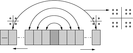
FIGURE 10.2
Illustrating the effect of I/Q mismatch on OFDM systems.
N
s
2
N − 1
1
DC
Frequency subcarriers
N
s
–1
1
4190_book.fm Page 283 Tuesday, February 21, 2006 9:14 AM