Tsoulos George (ред.) MIMO System Technology for Wireless Communications
Подождите немного. Документ загружается.

284 MIMO System Technology for Wireless Communications
with and without I/Q mismatch cancellation for MIMO2×
2, SIMO1×
2, and
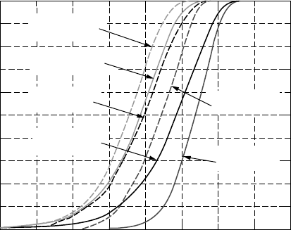
SISO systems. These figures show that there is a 5dB improvement due to
I/Q mismatch cancellation in a 2 ×
2 system, and about 2.5dB in the SISO
and SIMO1×
2 cases. This highlights the importance and efficacy of I/Q
mismatch cancellation in MIMO-OFDM systems. It can also be observed
from Figure 10.3(b) and Figure 10.4 that receive diversity (N v
2M
) cancels
I/Q mismatch, albeit being a suboptimal solution [9].
10.4.2.1 A Simulation Model for I/Q Mismatch
The models for frequency-dependent I/Q mismatch reported in the literature
are simplistic and consider a linearly varying gain and phase on each of the
subcarriers [5]. I/Q mismatch can be modeled much more realistically (sim-
ilar to what is observed on the testbed) by controlling the gain, phase, and
delay mismatches. The measure of I/Q mismatch used is the average image
suppression (or a plot of the per subcarrier image suppression). On the 2 ×
2 MIMO testbed the average I/Q mismatch is approximately –20dB. This
can be modeled in the simulator by choosing an I/Q gain mismatch of 0.91
dB, delay mismatch of 5% of Ts, and a phase mismatch of 2.8°. This is
illustrated in Figure 10.5.
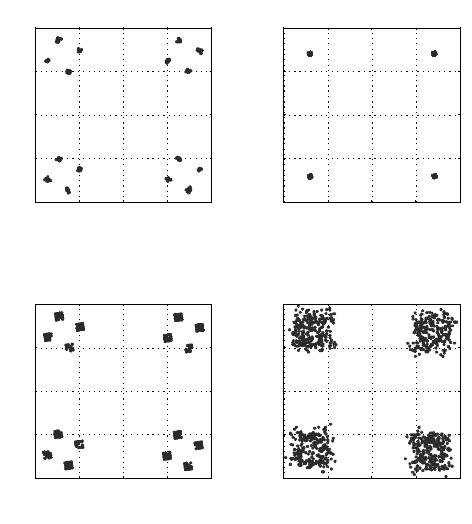
FIGURE 10.3
4QAM at 40dB SNR in the presence of I/Q mismatch in (a) SISO, (b) SIMO1×
2, (c) MIMO 2x2,
(d) MIMO4 ×
4.
0.5
0
−0.5
−1 −0.5 0
(a)
(c) (d)
(b)
0.5 1
−1 −0.5 0 0.5 1
−1 −0.5 0 0.5 1
−1 −0.5 0 0.5 1
1
0.5
0
−0.5
−1
1
0.5
0
−0.5
−1−1
1
0.5
0
−0.5
−1
1
SISO
SIMO1×2
MIMO2×2 MIMO4×4
4190_book.fm Page 284 Tuesday, February 21, 2006 9:14 AM
Multi-Antenna Testbeds for Wireless Communications
285
10.4.3 Phase Noise
An important analog impairment in any wireless transceiver is phase noise.
It degrades the performance of the transceiver in the up- and down-conversion
process of the RF chain. The Local Oscillator (LO) signals are not perfectly
sinusoidal, but rather show random fluctuations of the phase/frequency
around the desired LO frequency, which results in skirts in the power spectral
density of the LO signal. The wider the power spectrum skirt, the poorer
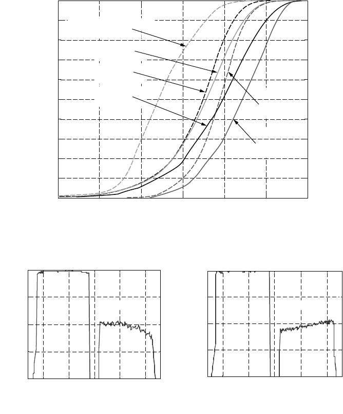
FIGURE 10.4
CDF of slicer SNR with and without I/Q mismatch cancellation on the testbed.
FIGURE 10.5
Image suppression (a) on the testbed and (b) in the simulator.
0
1
0.9
0.8
0.7
0.6
0.5
Probability(slicer SNR ≤ abscissa)
0.4
0.3
0.2
0.1
0
5 10 15 20
Slicer SNR
25 30
SISO, no IQ mismatch
cancellation
MIMO, with IQ mismatch
cancellation
MIMO, no IQ mismatch
cancellation
SIMO, with IQ
mismatch
cancellation
SIMO, no IQ
mismatch
cancellation
SISO, with IQ mismatch
cancellation
0
Power in
d
B
−10
−20
−30
−40
0
Power in dB
−10
−20
−30
−40
−100 −50
0
(a) (b)
Subcarriers
50
100 −100 −50
0
Subcarriers
50
100
−20.17 dB −20.40 dB
4190_book.fm Page 285 Tuesday, February 21, 2006 9:14 AM
286 MIMO System Technology for Wireless Communications
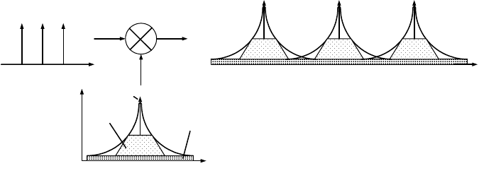
the quality of the LO. A simple model for phase noise in a multi-carrier
system is illustrated in Figure 10.6.
This model [10] represents the three components of the power spectrum
skirt: (a) the ideal and desired pulse, (b) close-in phase noise and (c) sideband
phase noise. The close-in phase noise has a relatively high power and is
band-limited by the loop bandwidth of the Phase Locked Loop (PLL) gen-
erating the LO signal. The PLL magnifies the close-in phase noise, which
mainly determines the noise performance of the receiver. It can be mitigated
with a proper design of the PLL circuit, as described later. The amount of
the sideband phase noise is mainly given by the phase noise characteristic
of the Voltage Controlled Oscillator (VCO) used in the PLL circuit. In a multi-
carrier system (as shown in Figure 10.6), the close-in phase noise is common
to all the carriers after an up- or down-conversion and can be cancelled in
software. The sideband phase noise overlaps and causes Inter-Carrier Inter-
ference (ICI). The interference due to the superposition of the skirts from all
the other subcarriers is random in nature.
The effects of the phase noise can be reduced by a proper hardware design
or can be cancelled in the demodulator. Both approaches are discussed in
the following sections.
10.4.3.1 Design of Low Phase Noise Local Oscillators
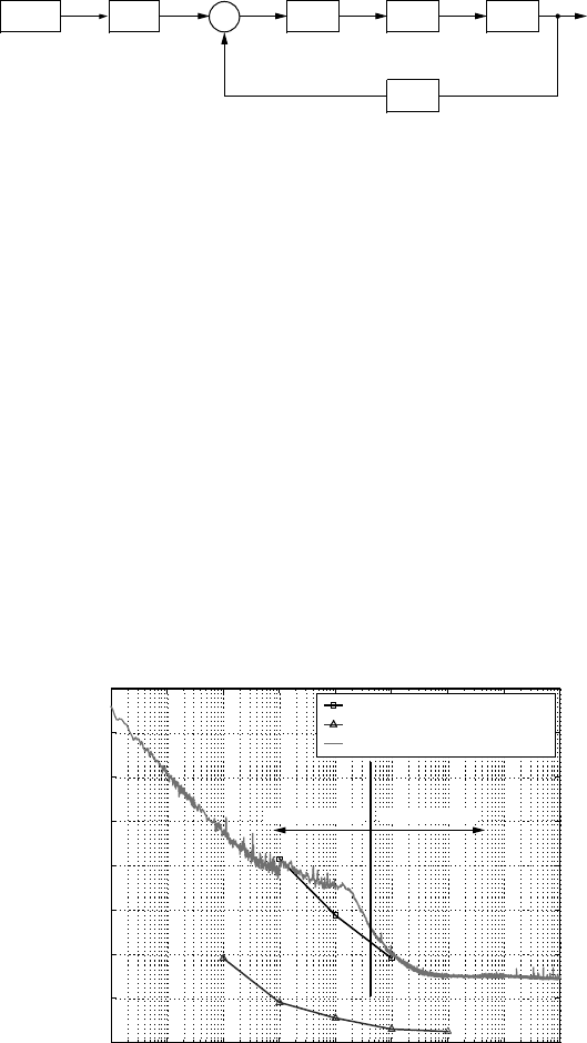
Figure 10.7 shows a block diagram of the PLL circuit that was used to
generate the low phase noise LOs in the 5.25 GHz MIMO-OFDM testbed.
The basic PLL consists of a phase frequency detector (PFD), a charge pump
(CP), a loop lowpass filter (LPF) and a voltage-controlled oscillator (VCO)
[9,11]. In the feedback loop is a divide-by-N block to generate the high
frequency LOs from the crystal (Temperature Compensated Crystal Oscilla-
tor, TCXO). At the input there is also an input reference divider R. Each block
contributes to the total phase noise at the output [12]. Analysis of the PLL
FIGURE 10.6
Phase noise in multi-carrier transceivers.
Subcarriers
Frequency
(a) Ideal
impulse
(b) Close-
in PN
LO
(c) Sideband PN
Frequency
Power
Frequency
4190_book.fm Page 286 Tuesday, February 21, 2006 9:14 AM
Multi-Antenna Testbeds for Wireless Communications
287
shows that the close-in phase noise can be reduced by minimizing the con-
tributions from the reference and feedback dividers as well as the phase
noise of the TCXO. In addition, choosing the feedback divider N small and
the reference divider R large reduces the close-in phase noise further. For
frequency offsets outside the loop bandwidth, the phase noise is dominated
by the VCO. Figure 10.8 shows the frequency spectrum of the TCXO and
the VCO used to generate the 1.75GHz LO at the transmitter in the 5.25GHz
MIMO OFDM testbed. It can be seen that within the loop bandwidth, the
PLL magnifies the phase noise (close-in part). Outside of the loop bandwidth
(sideband part), the phase noise of the PLL converges with the VCO, as
predicted by theory.
For reference, the phase noise measured at 100kHz frequency offset of the
LO frequencies was in the range of –120 dBc/Hz to –105 dBc/Hz for the
5.25 GHz MIMO-OFDM testbed.
FIGURE 10.7
Basic PLL block diagram
FIGURE 10.8
Phase noise power spectral density.
PF D
÷
N
÷
R
TCXO CP LPF
VCO
LO
−
+
0
Transmitter LO1(1.75 GHz)
VCO
TCXO
Transmitter LO1(1.75 GHz)
Phase noise(dBc/Hz)
−20
−40
−60
−80
−100
−120
−140
−160
10
0
10
1
10
2
10
3
Frequency offset(Hz)
10
4
10
5
10
6
10
7
10
8
Close-in PN
Sideband PN
4190_book.fm Page 287 Tuesday, February 21, 2006 9:14 AM

288 MIMO System Technology for Wireless Communications
10.4.3.2 Phase Noise Cancellation in the Demodulator
by Signal Processing
The effects of phase noise in SISO-OFDM systems has been extensively
analyzed and reported in the literature [13–15]. The results can be extended
to MIMO-OFDM systems. The per-subcarrier received signal after the FFT
can be represented as
(10.1)
where X
(ke
), Y
(ke
),
and H
(ke
) represent the transmit data vector, receive data
vector, and the channel matrix, respectively. N
s
is the number of subcarriers
and k
is the index of the subcarrier under consideration. MIMO decoding
involves reversing the effect of the channel and estimating each of the trans-
mitted data streams by left multiplying Y
(
ke
)
in Equation 10.1 with the weight
matrix W
(ke
), which is an estimate of the pseudo-inverse of the channel
matrix H
(ke
). The result is
(10.2)
The first term represents the estimated data vector. The second and third
terms represent the interference due to phase noise. The second term repre-
sents the “common phase error” (CPE) and is called this because its effect
is an identical phase rotation on all the subcarriers and all the transmit data
streams. This term can be estimated and corrected for every MIMO-OFDM
symbol. The CPE term is also scaled by the transmit signal on each subcarrier.
Therefore, in a MIMO system, as the number of transmit branches increases,
the CPE term decreases. The third term is the sum of the projection of the
phase noise skirts on all the other subcarriers and is commonly called the
inter carrier interference (ICI) due to phase noise. This is random in nature
and needs to be minimized by proper choice of the VCO.
The impact of canceling the CPE part of phase noise was evaluated on the
5.25 GHz 2 ×
2 MIMO-OFDM testbed. The results are shown in Figure 10.9.
It can be observed that canceling CPE has a much bigger impact on SISO
systems (approximately 4–4.5dB SNR gain) than on the 2 ×
2 MIMO system
(1.5–2 dB SNR gain). This is because the testbed is a power constrained
Yk Hk Xk
j
N
lHkXk
S
l
N
s
() ()() () ()()
e
=
ee
+
ee
¬
®
¼
¾
=
K
0
=
e
¨
¨
+
1
0
1
2
() ( ) ( )
()
j
N
lHkXke
S
l
N
j
lk k
N
s
K
U
SS
s
kkk
N
Vk
= |
e
¨
+
0
1
,
()
ˆ
() ()()
ˆ
() ()
ˆ
()Xk WkYk Xk
j
N
lXk
PN
s
e
=
ee
=
e
+
e
¬
®
¼
K
¾¾
=
=
=
¨
¨
+
e
l
N
s
s
l
N
s
k
j
Wk
N
lHkXk
0
1
0
1
0
()
() ( ) ( )
,
K
kkk
N
s
j
lk k
N
s
eVk
|
e
e
¨
+
e
1
2U ()
()
4190_book.fm Page 288 Tuesday, February 21, 2006 9:14 AM
Multi-Antenna Testbeds for Wireless Communications
289
system (the total transmit power is divided equally among the two trans-
mitters), and the CPE term is scaled by the data transmitted on each sub-
carrier of an OFDM system. Therefore CPE cancellation yields a smaller
improvement in the MIMO system. On the testbed, phase noise caused a
performance ceiling at 27dB SNR during the benchtop calibration process,
and it was removed after adding the CPE cancellation algorithm to the
demodulator.
10.4.3.3 A Discrete-Time Simulation Model for Phase Noise
Although analytical results show that the phase noise process has a Power
Spectral Density (PSD) that falls off at 1/f
2
[16], in reality (on hardware) the
phase noise PSD flattens out for large frequency offsets [17]. In [18] Salz
mentions (although in the context of laser phase noise) that the spectral
density of this phase noise has a 1/f
to 1/f
2
characteristic up to around 1 MHz
offset and is flat for higher frequencies. Also, at very low frequency offsets,
it has a 1/f
3
characteristic [17]. In discrete time simulations, it is difficult to
model phase noise to exactly match with what is measured on the testbed.
Approximate models with a 1/f
characteristic are used. Generally, the phase
noise process is modeled with an FIR filter that is generated with a user-
defined mask as in [15,21]. The user-defined mask is a rough approximation
of the PSD measured using a spectrum analyzer or a phase noise meter.
Although this method can model the phase noise behavior to be close to
what is observed on the hardware, the FIR filter can be fairly large, and
simulations are slow. An alternative method proposed by Kasdin [19,20] in
FIGURE 10.9
CDF of slicer SNR for indoor wireless measurements with SISO, SIMO1×
2, and MIMO2×
2 with
and without CPE cancellation.
Impact of phase noise cancellation on the testbed(EE54–114)
Probability
(
slicer SNR ≤ abscissa)
1
0.9
0.8
0.7
0.6
0.5
0.4
0.3
0.2
0.1
0
0 5 10 15
Slicer SNR
20 25 30 35 40
MIMO, no CPE
cancellation
MIMO, with CPE
cancellation
SISO, with CPE
cancellation
SISO, no CPE
cancellation
SIMO, with CPE
cancellation
SIMO, no CPE
cancellation
4190_book.fm Page 289 Tuesday, February 21, 2006 9:14 AM
290 MIMO System Technology for Wireless Communications
the early 1990s models phase noise using an ARMA process with an IIR
filter. This is an elegant method that can model any kind of power law noise
(ex. 1/f
, 1/f
2
, etc.). Although not widely discussed and used in the wireless
communication literature in the context of phase noise, it is a popular method
in industry (an example: MATLAB Simulink). This method was used to
model phase noise in the simulator that was used to analyze and compare
the performance of the 5.25 GHz MIMO-OFDM testbed.
10.4.4 Benchtop Calibration of the 5.25 GHz 2 ××
××
2 MIMO Testbed
This section briefly discusses the results of the entire benchtop calibration
process of the 5.25 GHz 2 ×
2 MIMO broadband testbed. The discussion that
follows considers uncoded SISO links, i.e., the wireless channel was replaced
with RF cables and variable attenuators between individual (paired) radio
units, resembling SISO AWGN channels.
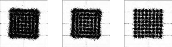
The combined effect of CPE phase noise removal and I/Q mismatch can-
cellation is illustrated in Figure 10.10 for the case with 64-QAM modulation
and approximately 20 dB SNR.
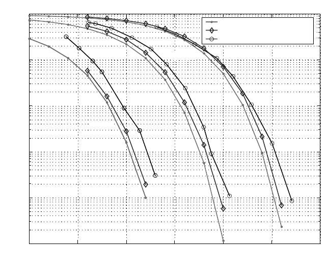
Figure 10.11 plots the symbol error rate curves for various signal constel-
lations and compares the testbed with theory and simulation when the
testbed is in perfect-timing mode. This means that the clock signal, which
also drives the LOs, is common to both the transmitter and the receiver units.
The results lie within 1–2 dB of the theoretical curves. The simulator, with
all the analog impairments modeled to match the testbed’s, is within 1 dB
of the testbed’s performance. The slight difference between the simulations
and the testbed is mainly due to the non-white nature of the noise on the
testbed, caused by non-linearities in the RF sections. These were not modeled
in the simulator.
An important metric to measure testbed performance is the implementa-
tion loss, which compares the average SNR at the input of the decision device
FIGURE 10.10
A 64 QAM constellation measured on the testbed at an input SNR of 20dB (a) without I/Q
mismatch cancellation and phase noise (CPE) cancellation, (b) with I/Q mismatch cancellation
but no phase noise (CPE) cancellation, (c) with I/Q mismatch cancellation and phase noise
(CPE) cancellation.
2
1
0
0
(a)
2
−1
−2
−2
2
1
0
0
(b)
2
−1
−2
−2
2
1
0
0
(c)
2
−1
−2
−2
4190_book.fm Page 290 Tuesday, February 21, 2006 9:14 AM
Multi-Antenna Testbeds for Wireless Communications
291
of the receiver (“slicer SNR”) vs. the SNR at the input of the receiver. The
difference in dB between the input SNR and the slicer SNR is the implemen-
tation loss. Figure 10.12 plots the implementation loss of the testbed in perfect
and non-perfect timing modes and compares the results with the simulator.
Also plotted is the implementation loss when the carrier frequency synchro-
nization algorithm is turned on and the testbed is in perfect timing mode.
This quantifies the impact of the frequency offset estimation errors and
allows for incorporating it into the system’s performance data sheet. In
perfect timing mode, when the I/Q mismatch canceller and phase noise
canceller are turned on, the implementation loss is within 2 dB in the entire
SNR range up to 30 dB. However, the loss is higher in the non-perfect timing
mode due to estimation errors in the synchronization algorithms. In this
case, it increases to about 3 dB at an input SNR of 25 dB. It can also be
observed that the carrier frequency offset estimation errors start having an
impact on the implementation loss at about 25 dB, increasing to about 3 dB
at 30 dB. In all these cases, it can be observed that with all the analog
impairments modeled, the simulator matches the testbed very closely. Other
key parameters of the RF and analog frontend (AFE) were measured as well
and are listed in Table 10.2.
FIGURE 10.11
SER calibration curves for the 5.25 GHz testbed over AWGN channel and in perfect timing
mode.
10
0
SER for 4QAM, 16QAM and 64QAM
eoretical AWGN curves
Simulation curves
Testbed
10
−1
16QAM
SER
10
−2
10
−3
10
−4
10
−5
0 5 10 15
Input SNR (dB)
20 25 30
64QAM
4QAM
4190_book.fm Page 291 Tuesday, February 21, 2006 9:14 AM

292 MIMO System Technology for Wireless Communications
FIGURE 10.12
Implementation loss vs. input SNR curves for the 5.25 GHz 2 ×
2 MIMO testbed in perfect
timing and non-perfect timing modes.
TABLE 10.2
System Parameters of the 5.25 GHz 2 × 2 MIMO Testbed
Radio architecture Heterodyne
System setup 2 × 2 (extendible to 4 × 4 antennas)
Carrier frequency 5.25 GHz
Signal bandwidth 25 MHz
Effective bandwidth 21.5 MHz
TCXO temperature stability <1 ppm (–10°C to +60°C)
Transmitter power –13 dBm to +18 dBm
Transmitter D/A converter 16 Bits/100 MHz
Receiver noise figure 7.93 dB
Receiver sensitivity –99 dBm
Receiver dynamic range 70 dB
Receiver IIP3 –25.4 dBm
Receiver A/D converter 14 Bits/25 MHz or 50 MHz
Image suppression Approx –20 dB
Local oscillator phase noise
@100 KHz offset
–120 dBc/Hz to –105 dBc/Hz
10
Comparing perfect and non-perfect timing modes
9
8
7
6
5
4
3
2
1
0
16 18 20 22 24
S
N
R
SNR
26 28 30 32
Simulation—non-perfect timing
Simulation—perfect timing, tracking ON
Simulation—perfect timing, no tracking
Testbed—non-perfect timing
Testbed—perfect timing, tracking ON
Testbed—perfect timing, no tracking
4190_book.fm Page 292 Tuesday, February 21, 2006 9:14 AM
Multi-Antenna Testbeds for Wireless Communications 293
10.4.5 Radio Receiver Distortion
An example from the development of the narrowband, DSP-based MIMO
testbed might be illustrative of both the impact of radio distortion and for
the need of emulation and simulation. The narrowband wireless modem was
built and tested in 2002 using the powerful concept of a super-orthogonal
trellis code [39,40]. Simulations of the whole baseband system were com-
pleted and performance looked quite promising (see lower curves on Figure
10.13a). During the calibration stage the system was subject to a real radio
and no fading (benchtop and cabled) and the system had some implemen-
tation loss but otherwise performed well. The next stage of calibration intro-
duced rapid time varying fading with a channel emulator and surprisingly
a significant error floor was produced (see upper curves on Figure 10.13a).
The cause of this degradation was not at first apparent.
The source of the degradation was a non-linearity in the radio receiver for
the testbed. The radio was implemented using a single chip radio frequency
transceiver that was designed for GSM applications (Analog Devices
AD607). This radio system caused some significant distortions to the received
linear modulated signal because of a significant non-linearity in the IF ampli-
fier. This distortion destroyed the Nyquist characteristics of the pulses in the
linear modulation and resulted in significant inter-symbol interference (ISI)
(see the scatter diagram in Figure 10.13b). These distortions in a time flat
fading environment did not cause significant degradation as the benchtop
calibration tests demonstrated, but for reasons that were not clear at first,
these distortions caused significant degradations in time varying fading.
After significant effort [43] that iterated back and forth between the sim-
ulation environment and the channel emulator, the cause of the error floor
was identified. An error floor is caused by a situation where the distortion
in the radio causes an error in the absence of thermal noise. It is pretty clear
from the scatter plot that in the static channel an error would not be caused
by this ISI. In a rapidly varying channel the situation is significantly different.
Two issues impact time varying fading: ISI being relatively larger due to
deep fades and ISI causing biases in pilot symbol-based channel estimation
during a deep fade.
ISI has a bigger impact during a deep fade. In rapid fading the number of
symbols that are impacted by a deep fade is often a very small number.
Consequently, the channel gain for the symbol being detected during a deep
fading can be small, but the ISI, due to the other interfering symbols, can be
large since the channel gain for these symbols is also large. Consequently,
the scatter plot does not directly scale but has a form as seen on the right
side of Figure 10.14. Simulation showed that the error floor was partially
due to this interaction with fading and ISI.
ISI causes biases in the channel estimation, and this bias is another source
of errors in the absence of noise. This idea can best be explained by examining
the vector diagram on the left side of Figure 10.14. A deep fade occurs when
4190_book.fm Page 293 Tuesday, February 21, 2006 9:14 AM