Versteeg H., Malalasekra W. An Introduction to Computational Fluid Dynamics: The Finite Volume Method
Подождите немного. Документ загружается.

11.11 ASSEMBLY OF DISCRETISED EQUATIONS 327
and the mass flow rate through the west face is
F
w
=
ρ
(−1i + 0j) . (ui + 0j)1.0 =−
ρ
u =−F
Let us use the upwind scheme; then
ψ
(r) = 0 in equation (11.48) and
F
i
[
φ
U
+
ψ
(r)(
φ
U
−
φ
D
)/2] = D
i
(
φ
A
−
φ
P
)
+ (S
u
+ S
p
φ
P
) (11.50)
Now if we apply equation (11.48) with the parameters calculated above we
obtain
[F
e
(
φ
P
+ 0) + F
w
(
φ
W
+ 0)] = [D
e
(
φ
E
−
φ
P
)] + [D
w
(
φ
W
−
φ
P
)]
+ (S
u
+ S
p
φ
P
) (11.51)
F
e
φ
P
+ F
w
φ
W
= D
e
φ
E
− D
e
φ
P
+ D
w
φ
W
− D
w
φ
P
+ (S
u
+ S
p
φ
P
) (11.52)
Equation (11.52) can be rearranged in the form
a
P
φ
P
= a
W
φ
W
+ a
E
φ
E
+ S
u
(11.53)
where a
W
= D
w
− F
w
a
E
= D
e
a
P
= a
W
+ a
E
− S
p
+ (F
e
+ F
w
)
At first sight the above expressions for the coefficients appear to be slightly
different from those in (5.30). However, since F
w
=−F and F
e
= F, we obtain
discretised equation (5.31). Thus, we have
a
W
= D + Fa
E
= Da
P
= a
W
+ a
W
− S
p
+ (F − F)
It is important to note that F
w
has a magnitude and a sign in these unstruc-
tured grid calculations. In fact, it is negative (−F ) in this example, so equa-
tion (11.52) is the same as equation (5.29) in Chapter 5, where F
w
was treated
as a magnitude, i.e. an unsigned quantity. The use of vector algebra in the
derivation of the relevant equations allows us to recover the correct magni-
tude and sign of F
w
.
We show that Cartesian 2D expressions can also be recovered with rela-
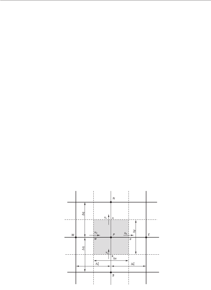
tive ease. Consider the 2D situation shown in Figure 11.23.
∑
all surfaces
∑
all surfaces
Figure 11.23 A 2D Cartesian
grid arrangement
ANIN_C11.qxd 29/12/2006 04:43PM Page 327

Table 11.3 shows the mass flow rates through each face, which are calcu-
lated using F
i
= n . (
ρ
u)∆A
i
.
328 CHAPTER 11 METHODS FOR DEALING WITH COMPLEX GEOMETRIES
Table 11.1
Outward normal Vector e
ξ
for the line
Cell face
vector to cell face between P and node
Area of cell face
East (e) n
e
= 1i + 0j Line PE: e
PE
= 1i + 0j ∆A
e
=∆y
West (w) n
w
=−1i + 0j Line PW: e
PW
=−1i + 0j ∆A
w
=∆y
North (n) n
n
= 0i + 1j Line PN: e
PN
= 0i + 1j ∆A
n
=∆x
South (s) n
s
= 0i − 1j Line PS: e
PS
= 0i − 1j ∆A
s
=∆x
The convection velocity vector is the same at all faces: u = ui + vj, where
u and v are both positive everywhere.
The other notation is just as standard: the diffusion coefficient is denoted
by Γ and the density by
ρ
. The normal vectors of the east, west, north and
south control surfaces of the control volume coincide with the lines con-
necting the nodes straddling these faces, so again the cross-diffusion term is
zero in this orthogonal grid. The values of the diffusion flux parameter for
the east, west, north and south faces from equation (11.24) are shown in
Table 11.2.
The essential parameters used in equation (11.48) are:
Control volume width in x-direction: ∆
ξ
=∆x for the lines PE and WP
Control volume width in y-direction: ∆
η
=∆y for the lines PN and SP
For equally spaced control volumes the distance between nodes is the
same, i.e. ∆x
PE
=∆x
WP
=∆x in the x-direction and ∆y
PN
=∆y
SP
=∆y in
the y-direction. Relevant unit vectors and the area for each side of a cell are
summarised in Table 11.1.
Table 11.2
Diffusion flux parameter D
i
for each face
East face West face
D
e
=∆y . 1.0 =∆yD
w
=∆y =∆y
North face South face
D
n
=∆x =∆xD
s
=∆x =∆x
Γ
∆
y
(0i − 1j) . (0i − 1j)
(0i − 1j) . (0i − 1j)
Γ
∆y
Γ
∆y
(0i + 1j) . (0i + 1j)
(0i + 1j) . (0i + 1j)
Γ
∆y
Γ
∆x
(−1i + 0j) . (−1i + 0j)
(−1i + 0j) . (−1i + 0j)
Γ
∆x
Γ
∆x
(1i + 0j) . (1i + 0j)
(1i + 0j) . (1i + 10j)
Γ
∆x
ANIN_C11.qxd 29/12/2006 04:43PM Page 328

11.12 EXAMPLE CALCULATIONS WITH UNSTRUCTURED GRIDS 329
Table 11.3
Mass flow rate F
i
through each face
East face West face
F
e
=
ρ
(1i + 0j) . (u i + v j)∆y =
ρ
u∆yF
w
=
ρ
(−1i + 0j) . (u i + vj)∆y =−
ρ
u∆y
North face South face
F
n
=
ρ
(0i + 1j) . (u i + v j)∆x =
ρ
v∆xF
s
=
ρ
(0i − 1j) . (u i + v j)∆x =−
ρ
v∆x
As in the 1D example we use the upwind scheme,
ψ
(r) = 0.
Now we apply equation (11.48):
F
i
[
φ
U
+
ψ
(r)(
φ
U
−
φ
D
)/2] = [D
i
(
φ
A
−
φ
P
) + S
D-cross,i
]
+ (S
u
+ S
p
φ
P
) (11.54)
If we substitute the information we have generated above, we obtain
[F
e
(
φ
P
+ 0) + F
w
(
φ
W
+ 0) + F
n
(
φ
P
+ 0) + F
s
(
φ
S
+ 0)]
= [D
e
(
φ
E
−
φ
P
) + 0] + [D
w
(
φ
W
−
φ
P
) + 0]
+ [D
n
(
φ
N
−
φ
P
) + 0] + [D
s
(
φ
S
−
φ
P
) + 0] + (S
u
+ S
p
φ
P
) (11.55)
F
e
φ
P
+ F
w
φ
W
+ F
n
φ
P
+ F
s
φ
S
= D
e
φ
E
− D
e
φ
P
+ D
w
φ
W
− D
w
φ
P
+ D
n
φ
N
− D
n
φ
P
+ D
s
φ
S
− D
s
φ
P
+ (S
u
+ S
p
φ
P
) (11.56)
This can be rearranged in the form
a
P
φ
P
= a
W
φ
W
+ a
E
φ
E
+ a
N
φ
N
+ a
S
φ
S
+ S
u
(11.57)
where a
W
= D
w
− F
w
a
E
= D
e
a
S
= D
s
− F
s
a
N
= D
n
and a
P
= a
W
+ a
E
+ a
S
+ a
N
− S
p
+ (F
e
+ F
w
+ F
n
+ F
s
)
Noting that values of F
w
and F
s
have negative signs, this equation gives the
same result as equation (5.31) extended to 2D. Instead of developing the dis-
cretised equation in the above manner we could have used the standard
expressions for the upwind scheme. With the correct sign for the mass flow
rate the upwind expression for any coefficient may be written as
a
i
= D
i
+ max(−F
i
, 0) (11.58)
It can be easily seen that this also results in the correct values for the
coefficients in the above example.
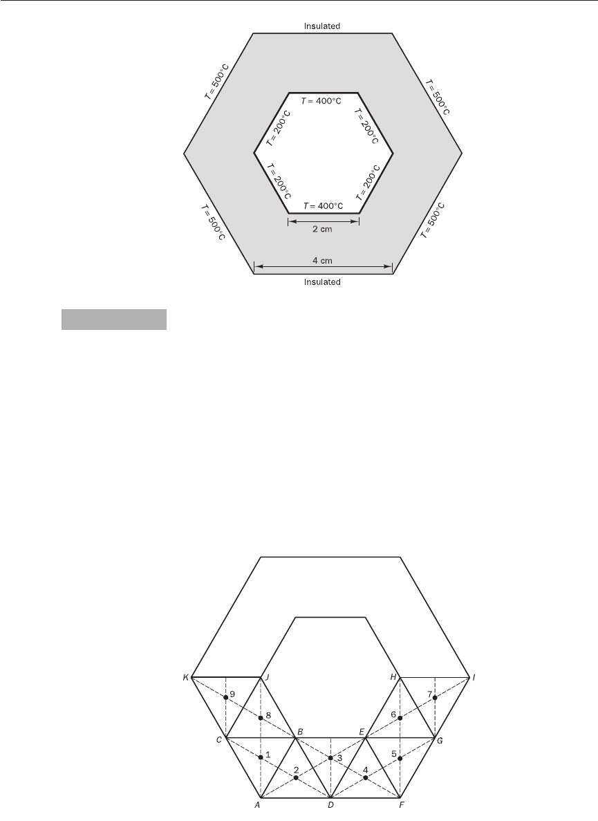
Consider the 2D hexagonal ring geometry shown in Figure 11.24. It is
required to calculate the temperature distribution given the temperature and
flux boundary conditions in the figure. The thermal conductivity of the
material is k = 50 W/m.K.
∑
all surfaces
∑
all surfaces
Example calculations with unstructured grids11.12
Example 11.1
ANIN_C11.qxd 29/12/2006 04:43PM Page 329
330 CHAPTER 11 METHODS FOR DEALING WITH COMPLEX GEOMETRIES
Figure 11.24 The geometry and
boundary conditions
The problem involves conduction only, so it is a diffusion problem without
sources. The geometry does not fit into Cartesian or cylindrical co-ordinates,
therefore an unstructured mesh is required. We use triangular cells, which
are an obvious choice for this problem. Alternatively, a mesh constructed of
quadrilateral cells is also possible.
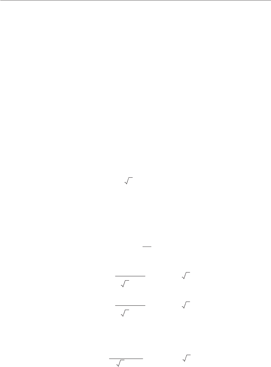
To demonstrate the method we have chosen a triangular mesh with equi-
lateral triangles, which has the advantage that it is an orthogonal unstruc-
tured grid, as shown in Figure 11.25. Since the normal vector to any face lies
exactly along the lines joining centroids, we do not need to calculate the
cross-diffusion term arising from non-orthogonality. Due to the symmetry
of the problem domain and the boundary conditions only a quarter of the
problem is required in the calculation. However, we would not be able to use
equilateral triangles everywhere, so it is more convenient to consider one
half of the geometry and use symmetry boundary conditions across lines HI
and KJ.
Figure 11.25 The grid used and
the notation
Solution
ANIN_C11.qxd 29/12/2006 04:43PM Page 330
11.12 EXAMPLE CALCULATIONS WITH UNSTRUCTURED GRIDS 331
The governing equation of heat conduction is
div(k grad T) = 0 (11.59)
Notations based on west, east, north and south nodes are meaningless in
unstructured grids and it is easier to refer to nodes by numbers. The
coefficients associated with each node will also be referred to by numbers.
However, we still use P to identify the central node under consideration.
We can use (11.48) directly to write the discretised equation for each
triangular control volume as follows:
D
i
(T
nb
− T
P
) = 0 (11.60)
where nb is the node number of the adjacent cell.
As illustrated earlier, the final discretised equation has the following form:
a
P
T
P
=∑a
nb
T
nb
(11.61)
where a
P
=∑a
nb
− S
P
The adopted mesh is so simple that many geometrical quantities required in
the calculation can be easily deduced using simple trigonometry. In a general
situation these would be calculated using vector algebra.
The area of all control volume faces is
∆A
i
=∆
η
= 2 × 10
−2
m
2
and the distance between nodes is
∆
ξ
= 2/ 3 × 10
−2
m
As the mesh is orthogonal the value of (n.n/n.e) = 1 for this case.
The given boundary temperatures are as follows: T
AC
= 500°C, T
CK
= 500°C,
T
BE
= 400°C, T
EH
= 200°C, T
BJ
= 200°C, T
FG
= 500°C and T
GI
= 500°C.
Edges AD and DF are insulated (zero-flux) boundaries.
Node 1
Flux through any face is
D
i
(T
N
− T
P
) =∆A
i
(T
N
− T
P
)
Flux through face AB is
k ××2 × 10
−2
= k 3 (T
2
− T
P
)
Flux through face BC is
k ××2 × 10
−2
= k 3 (T
8
− T
P
)
Face AC is a boundary, so the flux through this face is introduced as a source
term using the unstructured mesh equivalent of the half-cell approximation
first introduced in section 4.3:
Flux through AC is
k × 2 × 10
−2
= 2k 3(T
AC
− T
P
)
(T
AC
− T
P
)
(1/ ) × 10
−2
(T
8
− T
P
)
2/ × 10
−2
(T
2
− T
P
)
2/ × 10
−2
k
∆
ξ
∑
all surfaces
3
3
3
ANIN_C11.qxd 29/12/2006 04:43PM Page 331
Summation of fluxes through all three faces gives
k 3(T
2
− T
P
) + k 3 (T
8
− T
P
) + 2k 3 (T
AC
− T
P
) = 0
This can be simplified to
(1 + 1 + 2)T
P
= T
2
+ T
8
+ 2 × T
AC
4T
1
= T
2
+ T
8
+ 1000 (11.62)
It is not necessary to go through this derivation for every cell; we may
calculate coefficients using standard expressions for the coefficients of the
discretised equation and introduce boundary conditions as source terms.
In this example, coefficients connecting any neighbour node are given by
a
i
= D
i
= (k/∆
ξ
)∆A
i
, where ∆A
i
is the area of the face and ∆
ξ
is the distance
between the nodes. In our mesh the value of all coefficients is equal to
2 × 10
−2
= k 3
Node 2
a
1
= k 3, a
3
= k 3, and the face AD is an insulated boundary.
Flux through the boundary AD is zero (insulated boundary), so
S
u
= 0
S
P
= 0
a
P
= a
1
+ a
3
− S
P
After simplification the discretised equation for node 2 is
2T
2
= T
1
+ T
3
(11.63)
Node 3
BE is a constant temperature boundary, T
BE
= 400°C, and a
2
= k 3, a
4
= k 3.
Flux through BE is
k × 2 × 10
−2
= 2k 3(T
BE
− T
P
)
S
u
= 2k 3T
BE
S
P
=−2k 3
a
P
= a
4
+ a
6
− S
P
= (1 + 1 + 2)k 3
The discretised equation for node 3 is
4T
3
= T
2
+ T
4
+ 800 (11.64)
Node 4
Same as node 2; boundary DF is an insulated boundary (no flux).
The discretised equation for node 4 is
2T
4
= T
5
+ T
3
(11.65)
Node 5
Same as node 1; boundary FG is a constant temperature boundary.
Flux through FG is
(T
BE
− T
P
)
(1/ ) × 10
−2
k
(2/ ) × 10
−2
332 CHAPTER 11 METHODS FOR DEALING WITH COMPLEX GEOMETRIES
3
3
ANIN_C11.qxd 29/12/2006 04:43PM Page 332
11.12 EXAMPLE CALCULATIONS WITH UNSTRUCTURED GRIDS 333
k × 2 × 10
−2
= 2k 3(T
FG
− T
P
)
S
u
= 2k 3T
FG
S
P
=−2k 3
a
P
= a
4
+ a
6
− S
P
= (1 + 1 + 2)k 3
The discretised equation for node 5 is
4T
5
= T
4
+ T
6
+ 1000 (11.66)
Nodes 6 and 8
Similar to node 3; face EH is a constant temperature boundary, T
EH
= 200°C,
and face BJ is a constant temperature boundary, T
BJ
= 200°C.
The discretised equation for node 6 is
4T
6
= T
5
+ T
7
+ 400 (11.67)
The discretised equation for node 8 is
4T
8
= T
1
+ T
9
+ 400 (11.68)
Node 7
Face HI is a symmetry boundary, so no flux. Face GI is a constant temper-
ature boundary, T
GI
= 500°C.
Flux through GI is
k × 2 × 10
−2
= 2k 3(T
GI
− T
P
)
S
u
= 2k 3T
GI
S
P
=−2k 3
a
P
= a
6
− S
P
= (1 + 2)k 3
The discretised equation for node 7 is
3T
7
= T
6
+ 1000 (11.69)
Node 9
Same as node 7.
The discretised equation for node 9 is
3T
9
= T
8
+ 1000 (11.70)
Summarising the discretised equations:
4T
1
= T
2
+ T
8
+ 1000
2T
2
= T
1
+ T
3
4T
3
= T
2
+ T
4
+ 800
2T
4
= T
5
+ T
3
4T
5
= T
4
+ T
6
+ 1000
4T
6
= T
5
+ T
7
+ 400
3T
7
= T
6
+ 1000
4T
8
= T
1
+ T
9
+ 400
3T
9
= T
8
+ 1000
(T
GI
− T
P
)
(1/ ) × 10
−2
(T
FG
− T
P
)
(1/ ) × 10
−2
3
3
ANIN_C11.qxd 29/12/2006 04:43PM Page 333
Next, we rewrite this set of equations in matrix form:
G 4 −100000−10JGT
1
JG1000J
H−12−1000000KHT
2
KH 0K
H 0 −14−100000KHT
3
KH800K
H 00−12−10000KHT
4
KH 0K
H 000−14−1000KHT
5
K = H1000K (11.71)
H 0000−14−100KHT
6
KH400K
H 00000−1300KHT
7
KH1000K
H−10000004−1KHT
8
KH400K
I 0000000−13LIT
9
LI1000L
We note that the coefficient matrix is not banded. Due to the chosen control
volume numbering the off-diagonal entries appear at (1, 8) and (8, 1) in this
matrix. The solution is
GT
1
JG435.6436J
HT
2
KH423.7624K
HT
3
KH411.8812K
HT
4
KH423.7624K
HT
5
K = H435.6436K (11.72)
HT
6
KH318.8119K
HT
7
KH439.6040K
HT
8
KH318.8119K
IT
9
LI439.6040L
We do not have an analytical solution for comparison of our numerical
results. However, we can make several checks. First it can be seen that the
solution obtained is symmetric, i.e. T
2
= T
4
, T
1
= T
5
, T
6
= T
8
and T
7
= T
9
.
We can also check the flux balances across conducting boundary surfaces
(Table 11.4).
334 CHAPTER 11 METHODS FOR DEALING WITH COMPLEX GEOMETRIES
Table 11.4 Heat flux at conducting boundaries
Face Heat flux is given by Numerical values Flux value
AC k × 2 × 10
−2
50 × 2 × 10
−2
11146.8555
BE k × 2 × 10
−2
50 × 2 × 10
−2
−2057.8842
FG Same as AC 11146.8555
GI k × 2 × 10
−2
50 × 2 × 10
−2
10460.8941
EH k × 2 × 10
−2
50 × 2 × 10
−2
−20578.8247
BJ Same as EH −20578.8247
CK Same as GI 10460.8941
Net flux (heat balance) Σ fluxes =−0.0344 ≈ 0
(200 − 318.8119)
(1/ ) × 10
−2
(T
EH
− T
6
)
(1/ ) × 10
−2
(500 − 439.6040)
(1/ ) × 10
−2
(T
GI
− T
7
)
(1/ ) × 10
−2
(400 − 411.8812)
(1/ ) × 10
−2
(T
BE
− T
3
)
(1/ ) × 10
−2
(500− 435.6436)
(1/ ) × 10
−2
(T
AC
− T
1
)
(1/ ) × 10
−2
3
3
3
3
3
3
3
3
ANIN_C11.qxd 29/12/2006 04:43PM Page 334
11.12 EXAMPLE CALCULATIONS WITH UNSTRUCTURED GRIDS 335
As expected, in the finite volume method the fluxes of heat into and out
of the domain exactly balance. However, due to the coarseness of the grid,
the temperature distribution may not be very accurate. We need to perform
a high-resolution calculation to get better results. A high-resolution solution
for this problem is shown in Figure 11.26.
Figure 11.26 Temperature
distribution from a high-
resolution solution using a fine
mesh for the same problem
Convection–diffusion in a similar mesh
The method can be easily extended to convection–diffusion problems
employing a similar equilateral triangular mesh. For example, with the upwind
differencing method, using (11.58) the neighbour coefficients for convection–
diffusion in the equilateral triangular mesh shown in Figure 11.27 can be
written as
a
1
= D
1
+ max(−F
1
, 0) (11.73)
a
2
= D
2
+ max(−F
2
, 0)
a
3
= D
3
+ max(−F
3
, 0)
where D
i
=∆A
i
and F
i
=
ρ
(n.u)∆A
i
k
∆
ξ
Figure 11.27 Part of an
equilateral triangular grid
for 2D calculations
ANIN_C11.qxd 29/12/2006 04:43PM Page 335
The resulting discretised equation is
a
P
φ
P
=∑a
nb
φ
nb
+ S
u
(11.74)
where a
P
=∑a
nb
− S
P
+ (F
1
+ F
2
+ F
3
)
and F
1
, F
2
, F
3
have appropriate sign + if outwards and – if inwards
It was mentioned earlier that in unstructured and curvilinear structured grid
arrangements it is most convenient to store Cartesian velocity components
at the cell centres, where the pressure values are also stored. This is known
as a co-located arrangement. There are other methods which use staggered
arrangements, covariant and contravariant velocity components.
Figure 11.28 illustrates some of these methods for a sequence of cells
arranged along a 90° bend. In a staggered arrangement with Cartesian
336 CHAPTER 11 METHODS FOR DEALING WITH COMPLEX GEOMETRIES
Figure 11.28 Different
velocity vector arrangements for
curvilinear grids: (a) staggered
velocity arrangement;
(b) contravariant velocity
arrangement; (c) co-located
velocity arrangement
Pressure---
velocity coupling
in unstructured meshes
11.13
ANIN_C11.qxd 29/12/2006 04:43PM Page 336