Yam, Kit L. (ed.). The Wiley encyclopedia of packaging technology
Подождите немного. Документ загружается.

century using two sheets of cellulose nitrate material
clamped between two mold halves (2). Steam injected
between the sheets softened the material, sealed the
edges, and expanded it against the mold cavity (3).
Regrettably, cellulose nitrate is highly flammable, thus
limiting practical use.
More useful cellulose acetate and polystyrene thermo-
plastics became available in the 1920s and 1930s (4). By
the mid-1930s Owens-Illinois Glass Co. and PLAX Corp., a
newly formed division of Hartford Empire Co., each began
to develop proprietary plastic bottle manufacturing pro-
cesses based in part on automated glass-blowing machin-
ery then in use (2). Unfortunately, commercialized
cellulose acetate and polystyrene bottles were signifi-
cantly more expensive and, other than novelty, these
bottles offered no other marketable advantages over glass.
Low-density polyethylene provided the necessary ad-
vantage; in the mid-1940s, following World War II, PLAX
Corp. began blow molding the first commercial plastic
container in high-volume, a squeeze bottle for Stopette
underarm deodorant (2).
While commercial development of the squeeze bottle
was a significant event, blow molding of thermoplastic
materials in North America did not really begin until the
mid-1950s when high-density polyethylene became com-
mercially available (5); more important, commercial blow-
molding machinery becoming available in the late 1950s
(6). High-density polyethylene provided additional stiff-
ness while retaining some ‘‘squeezability’’ when required,
and commercial machinery provided an opportunity for
other companies to establish blow-molding manufacturing
operations. Until that time, a select few using proprietary
machinery were the only companies manufacturing plas-
tic containers. By 1960, over 55 builders were in the
business of manufacturing blow-molding equipment (7).
Many of these builders were unknown a year earlier and
most do not survive today.
BASIC PROCESS
Figure 2 illustrates the basic blow-molding process using
the extrusion molding method to create the parison.
In view Figure 2a, a blow-molding machine extrudes a
hot tube-shaped parison typically in a downward direction
from an extrusion head. Because the parison is tubular,
it has two substantially open ends. The machine places
the parison between two halves of a bottle blow-mold
cavity. In this view, the machine has a blow pin with an
end extending from the extrusion head and positioned
inside the parison. The blow pin is actually a metal tube
with a passage allowing a flow of air to enter inside the
parison at the appropriate time. While this is a common
blow pin placement, machinery builders and designers
have developed several other arrangements with similar
function.
In Figure 2b, once the parison reaches a proper length,
the machine’s clamp system closes the two mold halves
against each other to close off and seal the parison open
ends. At one end, the mold pinches the parison flat. At the
other end, adjacent to the extrusion head, the mold also
pinches the parison substantially flat while sealing it
around the blow pin. The pinching of the parison creates
flash material. Machinery, later in the manufacturing
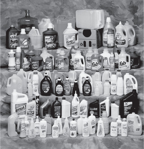
Figure 1. An array of extrusion blow-molded bottles.
(Courtesy of Graham Engineering Corporation.)
138 BLOW MOLDING
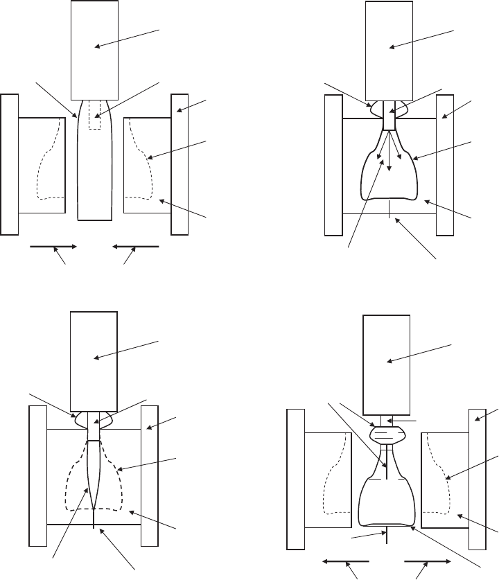
process, trims and recycles this flash. The flash portion is
often 20–50% of final bottle weight.
In Figure 2c, air flowing through the blow pin at an
elevated pressure inflates, thereby pressing and conform-
ing the parison to the mold cavity surfaces. The machine
holds the air pressure for a period sufficient to allow the
mold cavity to cool the conformed parison, thereby retain-
ing the molded shape of the container or bottle. Generally,
machinery circulates water through channels in the mold,
thereby maintaining a consistent mold temperature.
In Figure 2d, the machine ejects or removes the molded
bottle from the mold cavity, usually to one side or down-
ward. Typically, machinery trims away the flash still
attached to the bottle in a secondary operation.
Although Figure 2 shows the extrusion method for
creating the parison or preform, using the injection
method does not alter process fundamentals—in particu-
lar, inflation of the parison or preform.
EXTRUSION BLOW MOLDING
Container manufacturers can make bottles, jars, or drums
of nearly any size using extrusion-based blow-molding
methods. Extrusion blow molding has two main process
categories, that is, container manufacture using continu-
ous extrusion machinery and intermittent extrusion ma-
chinery. Each category has machinery subcategories
tailored to specific application requirements. Compared
Extrusion
Head
Bottle
Cavity
Blow Mold
Parison Blow Pin
Molding
Machine
Mold-Close Direction
(a)
(b)
Extrusion
Head
Bottle
Cavity
Blow Mold
Parison
Blow Pin
Molding
Machine
Parison
Parison Pinched
Top & Bottom
(c)
Air Flow through
Blow Pin
Extrusion
Head
Blow-Molded
Bottle
Blow Mold
Parison
Blow Pin
Molding
Machine
Parison Pinched
Top & Bottom
(d)
Extrusion
Head
Bottle
Cavity
Blow Mold
Flash/Trim
Blow Pin
Molding
Machine
Mold-Open Direction
Flash
Blow-Molded
Bottle
Figure 2. Basic blow-molding process sequence: (a) Parison extrusion; (b) mold close and parison pinch; (c) parison inflation and bottle
cool; (d) mold open and bottle eject.
BLOW MOLDING 139
to injection-based blow molding, mold tooling for the
extrusion blow process is relatively less expensive. In
addition, the extrusion blow process has relatively few
shape restrictions and is the only low-cost method for
manufacturing a bottle with an integral handle.
Continuous Extrusion
Machinery continuously forms the parison at a rate equal
to that required to blow, cool, and remove the molded
bottle. To avoid interference with parison formation, the
machine’s mold-clamping mechanism or system must
move quickly to capture the parison and return to a
blowing station, thereby creating space for the next par-
ison to form.
Builders have made machinery capable of molding
large containers, such as a 35-gal trash container, using
the continuous extrusion approach, but the approach is
better suited for smaller containers, typically 10 L (2.5 gal)
or smaller in capacity. In fact, most continuously extruded
blow-molded bottles are 4 L or less in capacity.
The continuous extrusion process is capable of molding
all commonly molded thermoplastic materials, but the
process is particularly ideal for molding heat-sensitive
PVC materials. Relatively low-pressure, slow uninter-
rupted flow of melted material through an extruder or
plasticizer and parison extrusion head helps minimize
thermal degradation of heat-sensitive polymers.
Several machinery configurations exist, but two ap-
proaches generally predominate: shuttle continuous and
vertical rotary continuous. Less common approaches in-
clude rising-mold continuous and horizontal rotary con-
tinuous configurations.
Figure 3 illustrates the shuttle continuous extrusion
approach. With this method, the blowing station is located
on one or both sides of the parison extrusion head. As the
parison reaches proper length, the blow mold and clamp
(while open) quickly shuttle to a point under the extrusion
head, closes to capture and then cut the parison from the
head, and return to the blowing station where the blow pin
enters to seal and then inflate the parison against the
mold cavity surfaces. With dual-sided machine concept, as
shown in the illustration, two clamp systems shuttle on
an alternating basis. To increase production output,
machines use multiple extrusion heads with multiple
mold cavities—for example, a triple parison head with
two triple mold cavity sets. Generally, the mold and clamp
slides or swings on an incline. This provides extra clear-
ance from the ever-advancing parison as the mold and
clamp moves to the blowing station. An alternative means
for providing additional clearance is by ‘‘bobbing’’ the
extrusion head up during the return movement and then
down following clamp movement.
The shuttle machinery configuration offers a number of
advantages. The configuration allows critical dimensions
of the bottle neck-finish to be ‘‘pre-finished’’ or ‘‘calibrated’’
in the mold with a water-cooled blow pin. This eliminates
the need for post-mold secondary sizing or machining
of the neck-finish area. Machinery operators also value
the easy mold tooling and process setup. Job changes on
shuttle continuous equipment can be relatively quick,
making the equipment ideal for a short production run.
On the other hand, the process has a relatively slow
parison extrusion rate requiring the hot plastic material
to have exceptional ‘‘melt’’ strength. That is, the parison
must not appreciably change shape from material flow
caused by its own weight as it extrudes from the head.
Shuttle continuous extrusion machines, particularly sin-
gle-sided machines, require the hot parison to hang for a
relatively long time.
A number of machinery builders supplying shuttle con-
tinuous blow-molding equipment have begun offering ‘‘long-
stroke’’ machines. These are either single-sided or dual-
sided alternating shuttle machines with relatively large
multicavity molds. These machines can have as many as 15
mold cavities in each mold set. Of course, the machine
Blow Mold
Extrusion
Head
Bottle
Cavity
Blow Pin
Mold-Shuttle Directions
Parison
Parison
Cutting
Knife
Blow Pin
Flash/Trim
Blow
Mold
Mold-open
& close is i
n
Direction of
View
Figure 3. Basic alternating shuttle
continuous-extrusion blow-molding
machine.
140 BLOW MOLDING
requires the extrusion head to extrude the same number of
parisons. In comparison, a more conventional shuttle ma-
chine typically has six of fewer cavities in each mold set.
Relative to conventional shuttle machines, the long-
stroke machine, predominantly in the dual-sided config-
uration, is capable of high production output per unit of
factory floor space the machine occupies. Single-sided
long-stroke machines can simplify integration of in-mold
labeling equipment and downstream bottle handling
equipment relative to dual-sided machines having similar
production output. On the other hand, the large mold set
and clamping system must travel a longer distance be-
tween the blowing station and parison extrusion head.
Moreover, the mold set and clamping system has a greater
mass; therefore, it is more difficult to accelerate and
decelerate. All things equal, an alternating shuttle ma-
chine with half as many parisons, mold tooling with half
as many cavities per side, and shuttle travel distance
substantially half as much will provide a faster per cavity
production rate than a single-sided long-stroke machine.
Figure 4 shows a typical alternating shuttle continuous-
extrusion blow-molding machine.
Recently, machinery builders have begun offering shut-
tle machines with tandem mold cavities. These machines
have a production output that approaches that of a rotary
machine while preserving the benefit of the pre-finished or
calibrated neck-finish. Normally, at the blowing station
the blow pin enters the parison from the top, primarily
because the molded bottle leaves the machine in an up-
right position, greatly facilitating downstream handling.
However, the blow pin can also enter from a bottom
position, thereby blow molding the bottle upside down. A
shuttle machine having tandem cavities produce two
bottles from one parison, one in the upright position, the
other in the upside-down position. Incorporated trim
tooling later separates the tandem bottles.
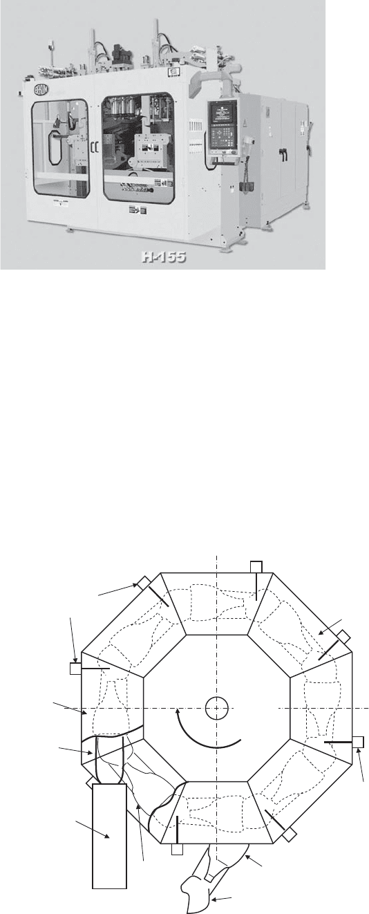
Figure 5 illustrates the vertical rotary continuous
machinery approach. The mold cavities circumferentially
mount to a wheel having a horizontal axis of rotation like
that of a Ferris wheel. In this approach, one of the mold
sets on the rotating wheel captures the parison as it
rotates past the parison extrusion head, in this case
extruding the parison upward, while other mold sets
simultaneously shape and cool bottles from previously
captured parisons; another mold set opens, allowing bottle
removal.
Figure 4. An alternating shuttle continuous-extrusion blow-
molding machine featuring a three-parison extrusion head be-
tween two mold clamp mechanisms. (Courtesy of Bekum America
Corporation.)
Blow-Molded
Bottle
Extrusion
Head
Bottle
Cavity
Parison
Blow Mold
Mold
Rotation
Direction
Needle
Blow Pin
Flash/Trim
(a) Mold-close &
Parison Pinch
(c) Mold-open
& Bottle Eject
Blow Mold
(b) Parison
Inflation &
Bottle Cool
Needle
Blow Pin
Mold-open &
Close is in
Direction of
View
Figure 5. Basic vertical rotary continuous-extrusion
blow-molding machine having a parison extruding
upward.
BLOW MOLDING 141
Generally, the machine extrudes a single parison and
each mold set has one cavity, but some machines have
multiple parison and cavity sets. Specific configuration
depends on mold and clamp design details—for example,
two cavities inline, face-to-face made from a single par-
ison; or two cavities side-by-side, each capturing its own
parison extruded side-by-side and in parallel. Direction of
mold open and close motion is either parallel to wheel axis,
radial to wheel axis, or ‘‘book’’ where one mold half hinges
from an edge of the other mold half. Once the mold cavity
closes, a needle blow pin punctures the parison. Air
flowing through the needle conforms the parison to the
cavity surfaces. Figure 6 shows a vertical rotary contin-
uous extrusion blow-molding machine having a single
parison extruding in an upward direction a moment before
the mold closes to capture. Note that the mold cavity in
Figure 6 has a shape to form a bottle having an integral
handle. In addition, Figure 6 shows a cylinder, (right-hand
corner) for actuating the needle.
The rotary approach has many advantages, primarily
for bottle applications requiring high production out-
put. The single parison extrusion head helps to maintain
bottle consistency between all mold cavities, particularly
for applications requiring a complicated multilayer or
coextruded polymer material structure. Another advan-
tage is that in-mold labeling systems, when used, are less
complicated because the same unit supplies labels for all
cavities. In addition, the vertical rotary approach has a
unique capability of holding the parison fast at the top and
bottom, allowing an opportunity to manipulate parison
material distribution in ways not as easily done with other
processes where the parison’s bottom end is free.
On the other hand, the vertical rotary approach, as
mentioned previously, typically requires the needle blow
pin to puncture the parison. For bottles, this puncture is
into a molded dome area above the bottle neck-finish. A
post-molding operation cuts off the molded dome with
other flash trimmings. Establishing final neck-finish di-
mensions further requires a sizing or machining opera-
tion. Machining the neck-finish area can allow plastic
chips to fall inside the bottle and potentially contaminate
any filled product. In addition, tooling job changes are
more complicated and typically take more time; however,
this is not necessarily a problem for long-term high
production applications.
Intermittent Extrusion
An intermittent extrusion blow-molding machine quickly
extrudes the parison after bottle removal from the mold
cavity. The mold-clamping system does not transfer to the
blowing station. Bottle molding, cooling, and removal all
take place under the parison extrusion head. This ar-
rangement allows the clamping system to be more simple
and rugged. Manufacturers typically use the intermittent
extrusion approach to make containers from 100 mL (3.4 fl
oz) to 210 L (55 gal).
Two machinery configurations predominate: recipro-
cating screw and accumulator head. A less common
configuration is a side-ram accumulator or shot-pot
approach. Polyolefin thermoplastic materials, parti-
cularly HDPE, are ideally suited for the intermittent
extrusion; unfortunately, its start–stop–start character
and extremely rapid parison extrusion rate is not best
for heat-sensitive materials.
Manufacturers typically consider reciprocating screw
machinery for containers less than 10 L (2.5 gal) in capacity.
The plasticizer of the reciprocating screw blow-molding
machine has an extruder screw that moves back as it helps
to melt the thermoplastic material. That melted material,
for the next parison, accumulates downstream of the
screw’s tip. During parison extrusion, the screw quickly
moves forward to push the accumulated material through
the extrusion head. Next, the mold clamping system closes
on the parison and blow pin. The parison then inflates
against the mold cavity while the reciprocating screw
begins to accumulate material for the next parison. Once
the molded container has cooled, the clamp opens allowing
container removal. The process then repeats.
For many bottle design configurations, the reciprocat-
ing screw machine allows ‘‘pre-finishing’’ of critical bottle
neck-finish dimensions during the molding process. Posi-
tioning the blow pin inside the parison before mold-close
allows a choice of two pre-finishing approaches. The
first, a so-called ‘‘ram-down’’ or ‘‘calibrated’’ pre-finishing
Figure 6. Mold cavity and upward extruding parison of a rotary
continuous-extrusion blow-molding machine. Previous mold (now
closed) holds the parison in position. Note, the needle blow-pin
actuating cylinder near upper left-hand corner and mold cavity
for a handleware bottle. (Courtesy of Graham Engineering
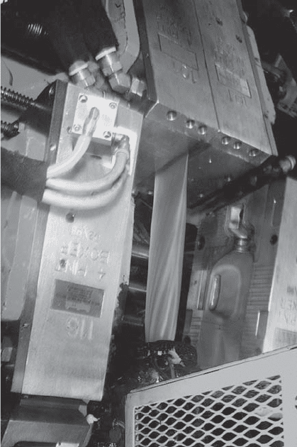
Corporation.)
142 BLOW MOLDING
approach provides a result substantially identical to the
approach used with shuttle continuous extrusion. The
second, a so-called ‘‘pull-up’’ pre-finishing approach, is
unique to intermittent extrusion machinery. The blow
pin for the pull-up approach moves upward a spit second
before the mold opens. During this upward movement, the
blow pin shears plastic material in a critical neck-finish
inside diameter area to create a precise, round, and
smooth inside surface for a closure to seal.
The pull-up pre-finishing approach is an innovation that
perhaps is singly most responsible for the success of HDPE
milk bottles. Substantially all of the HDPE milk bottles
made in the United States feature a neck-finish made using
the pull-up approach. The pull-up approach permits ex-
tremely lightweight containers that in turn reduces man-
ufacturing cost from less material expense and faster
(shorter) molding process from a reduced need for cooling.
Bottles featuring the pull-up made neck-finish use a low-
cost closure not requiring any secondary sealing material.
Instead, the closure features a standing circumferential
wedge that, when applied to the bottle, tightly engages the
smooth precise inside surface of the neck-finish to establish
a simple and highly effective seal. Figure 7 shows a
reciprocating screw blow-molding machine.
The accumulator-head intermittent-extrusion process
is ideal for heavyweight containers, such as 210-L (55-gal)
drums, and noncontainer items, such as parts for toys,
automotive ductwork, and the like. Generally, manufac-
turers will consider accumulator head machinery for
containers larger than 10 L in capacity. The accumulator
head features a tubular melt reservoir as part of the
extrusion head itself. The machine’s plasticizer feeds
melted thermoplastic material into the reservoir on a
first-to-enter, first-to-leave basis. Once a sufficient quan-
tity of melted material accumulates, a tubular plunger
within the head quickly extrudes the parison through a
head tooling annulus.
Similar to the accumulator-head, the side-ram or shot-
pot intermittent-extrusion process uses a single melt
accumulator that receives melted thermoplastic from the
plasticizer. The melt accumulator is not a component of
the extrusion head; instead, it features a piston or plunger
along side the plasticizer that pushes the material into a
manifold and then through multiple extrusion heads. It is
generally used for heavy container applications requiring
an excessive amount of accumulated melt that is greater
than the amount the reciprocating-screw process is cap-
able of accumulating. Recently, machinery builders are
offering the ‘‘shot-pot’’ equipment for classic reciprocating-
screw applications, particularly in situations where a fine-
mesh screen filters the melt to remove contaminates likely
in post-consumer recycled material.
Head Tooling, Parison Programming, and Head-Tooling
Ovalization
By definition, the extrusion process requires the parison to
be a hollow tube having a diameter and wall thickness
adequate to properly form the container. Head tooling
consists of two components: a generally circular die sub-
stantially establishing, in cross-section, the parison’s
outer diameter and a generally circular mandrel substan-
tially establishing the parison’s inner diameter. In combi-
nation, these two components create an annulus through
which the parison extrudes. The diametrical difference
forms a gap between the die and mandrel that establishes
parison wall thickness. For simple less demanding con-
tainer applications, the gap remains uniform.
Parison inflation in the blow-mold cavity is not even.
Some areas will expand more, thus tending to thin more.
Parison programming is a technique to compensate parti-
cularly for more demanding container applications. Pro-
gramming permits the molding technician to place extra
material in the container where needed and remove
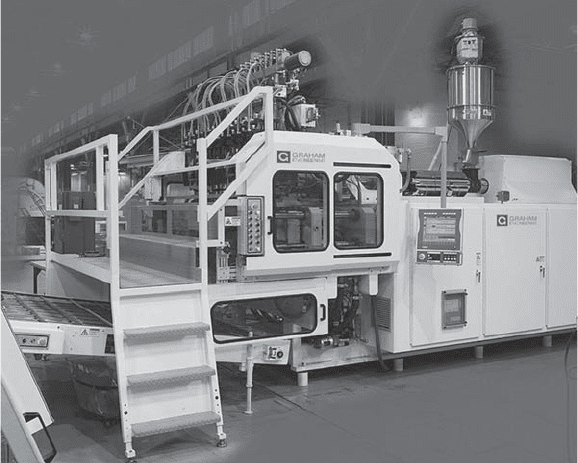
Figure 7. Typical reciprocating-screw intermittent-
extrusion blow-molding machine. (Courtesy of Graham
Engineering Corporation.)
BLOW MOLDING 143
material where it is not needed, ultimately allowing
improved container performance while making container
wall-thickness more consistent and likely reducing over-
all container weight and cost. Programming dynamically
changes annulus gap size by moving either the die or the
mandrel relative to the other to a specific profile as the
parison extrudes to create axial circumferential zones
or rings of thicker or thinner material in the parison
corresponding to areas within the blow-molded container
requiring more or less material.
Head-tooling ovalization is also a technique to compen-
sate areas of the parison that tend to thin more. By
changing the shape of either the die or mandrel from
round to slightly oval, the corresponding gap of the
annulus created by the die and mandrel circumferentially
varies. During parison extrusion, ovalized tooling creates
‘‘stripes’’ of thicker or thinner material parallel to the
parison’s axis that correspond with areas of the container
requiring more or less material. In other words, the
parison in circular cross section has areas thicker than
other areas within that cross section.
Generally, ovalizing head tooling is a fixed approach,
not dynamic, as is the case with parison programming.
While ovalized head tooling and parison programming
separately or together can significantly improve material
thickness distribution in the blow-molded container, some
areas of the blow-molded container will always remain
slightly thicker or thinner than other areas. The molding
technician selects a degree of ovalization in combination
with parison programming that is a compromise of wall
thickness requirements in various container areas. For
example, the container’s sidewall may be slightly thicker
than necessary to have adequate wall thickness in the
container’s chime area.
In general, it is not practical or cost effective for most
container applications to have dynamic ovalization pro-
grammed to a specific profile as with conventional parison
programming. However, in large somewhat heavy contain-
ers, such as the 210-L (55-gal) drum, dynamic ovalization
is justifiable. Even with parison programming and fixed
ovalization, a drum’s chime area can still have significant
differences in material thickness. Dynamic ovalization
features a die having flexible lips. Applying a force to
the lips during parison extrusion causes the normally
circular die to slightly distort into various oval shapes as
determined by a programmed profile suitable to specific
container requirement, thereby reducing an otherwise
necessary material thickness compromise in other parts
of the container.
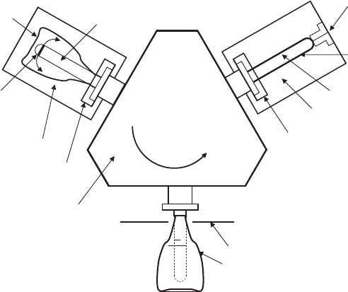
INJECTION BLOW MOLDING
In the classic injection blow-molding process, the plastici-
zer injects melted plastic into a closed mold having a cavity
and a core rod to create an injected-molded ‘‘test tube’’-
shaped preform having an integral neck-finish. While still
hot, the injection-molding machine transfers the preform
on the core rod to a bottle blow-mold cavity. Pressurized air
passing through a valve in the core rod inflates the pre-
form, conforming it to the blow-mold cavity surface. Once
cooled, the mold cavity opens and the machine removes the
blow-molded bottle from the core rod.
Early injection blow-molding techniques were substan-
tially two-position tooling adaptations of conventional
injection molding machines (8). A shortcoming of these
adaptations was that the injection and blow-mold stations
stood idle during bottle removal. The blow-molding in-
dustry generally credits Angelo Gussoni with inventing a
three-station injection blow-molder (9). A third station
improved efficiency by allowing bottle removal while the
other two stations molded either the next preform or the
next bottle.
Initially, Gussoni also adapted this three-station concept
to available conventional injection-molding machines. La-
ter, purpose-built three-station injection blow-molders
evolved that today have become an industry standard.
Figure 8 illustrates the basic three-station injection
blow-molding process. Note that the process requires three
core rods for each preform-mold and blow-mold set.
The injection blow-molding process has a number of
advantages. The process is flash- or scrap-free. Molded
bottles do not require secondary trimming. Injection mold-
ing the preform accurately maintains critical neck-finish
dimensions, an important consideration for complex child-
resistant and snap-on closures common on pharmaceuti-
cal bottles. Bottle weight control is extremely precise,
accurate within a range of 0.2 g or less. Bottle surface
gloss and texture is pristine and consistent. For typical
applications having a capacity less than 250 mL, the
injection blow-molding process is generally less expensive
than extrusion blow-molding processes. For vials—for
example, 1, 5, or 10 mL in capacity—and other very small
bottles, bottle manufacturers have only one cost-effective
process choice, injection blow molding.
On the other hand, machinery configurations generally
limit bottle size to 4 L (1 gal) or less capacity. Because of
the relative high cost of mold tooling, the injection blow-
molding process is usually not economically justifiable for
typical bottle applications having a capacity greater than
500 mL. Finally, the process limits bottle shape and pro-
portion. Although not a problem for most bottle applica-
tions, the process is not ideal for extremely flat, overly tall
and thin, offset neck-finish, or handleware bottle shapes.
Table 1 contrasts important advantages of injection blow
molding versus extrusion blow molding.
Pharmaceutical and cosmetic product applications
often require small bottles with precise neck-finishes.
Furthermore, these products are often expensive, de-
manding an equally high-value, quality package that
injection blow provides and not always available from
the extrusion-blow alternative.
Many thermoplastic materials are injection-blow mold-
able, which could be difficult or impossible using extru-
sion-blow
processes. General-purpose
polystyrene is a
good example of a thermoplastic that injection-blow-mold-
ing machines routinely process. Because the core rod helps
to support the melted material during transfer to the
blowing station, injection-blow process does not require
the same degree of melt-strength that extrusion blow,
particularly continuous extrusion blow, requires. In addi-
tion, the injection-blow process adds a degree of molecular
144 BLOW MOLDING
orientation to the general-purpose polystyrene bottle that
enhances its impact resistance.
Other materials commonly molded with classic injec-
tion blow are high- and low-density polyethylene,
polypropylene, polyvinyl chloride, and polyethylene ter-
ephthalate. While the injection-blow process approach
provides beneficial molecular orientation to polystyrene,
other thermoplastics such as polypropylene or polyethy-
lene terephthalate, unfortunately, do not benefit. The core
rod of the classic injection-blow process remains inside the
preform; additionally, the preform length is approximately
the same as the container is tall, conditions that inhibit
beneficial molecular orientations of many other materials,
particularly in an axial direction.
EXTRUSION—INJECTION-MOLDED NECK PROCESS
This unique hybrid process combines advantages of injec-
tion blow with extrusion blow. Originally developed by
Owens-Illinois in the 1950s, the process is not much in use
today for manufacturing bottles, but a version is in use for
manufacturing constant velocity joint (CVJ) boots and
parts for other automotive bellows applications. The hy-
brid process features an injection-molded neck with an
extrusion-blow-molded body that provides a dimension-
ally accurate neck-finish without some of the bottle shape
and proportion limitations of injection blow. The hybrid
process can mold a flat oval bottle having an offset neck-
finish and integral blown-handle configuration typical of
extrusion blow with a high-quality neck-finish typical of
injection blow. While machinery is not high output, it is
ideally suited for integrating an in-mold labeling feature
without production penalty.
STRETCH BLOW MOLDING
Thermoplastic materials are polymers of relatively high
molecular weight—that is, of long polymer chains made of
hundreds to thousands of linked individual monomer
molecules. Normally, these long-polymer-chain molecules
entangle with other in random complex coils. Careful,
proper processing of some materials, such as polyethylene
terephthalate (PET) and polypropylene (PP), will estab-
lish and retain partial molecular orientation of the poly-
mer chains. In other words, the polymer chains become
somewhat aligned with each other in uniaxial and biaxial
directions.
While all blow-molding processes involve ‘‘stretching’’
the parison or preform in some fashion, ‘‘stretch blow
molding’’ or biaxial-orientation blow molding is a modified
process to achieve and retain polymer chain alignment in
biaxial directions within the blow-molded bottle, in parti-
cular within the bottle sidewall. Biaxial orientation can
significantly improve bottle impact strength, transpar-
ency, surface gloss, stiffness, and gas-barrier performance,
particularly in bottles greater than 250 mL in capacity.
Filled soft drink PET bottles, highly pressurized from
carbon dioxide gas, are an everyday reality because of
the stretch-blow process.
Fundamentally, the stretch-blow process requires pre-
cise conditioning of the preform to a temperature warm
enough to allow rapid inflation and molecular alignment
but cool enough to retard re-randomization of its molecu-
lar structure once aligned. Preform manufacture is by
either extrusion molding or injection molding; however,
dimensional precision provided by injection molding has
allowed that approach to dominate in bottle manufactur-
ing today.
Most common polymers biaxial-oriented are polyethy-
lene terephthalate (PET) and polypropylene (PP). Other
polymers include polyvinyl chloride, acrylonitrile-based
copolymers, and a high-performance polyester, polyethy-
lene naphthalate.
Figure 9 illustrates typical preform and bottle propor-
tions. Note that the preform is significantly shorter than
the bottle. In comparison, conventional extrusion-blow
parison and injection-blow preform are substantially the
Air Flow
through Valve
in Core Rod
(b) Bottle Blow-
Molding Stage
(c) Bottle Eject Stage
Transfer
Direction
Preform Mold
Injection
Nozzle
Core Rod
Neck-Ring
Blow Mold
Neck-Ring
Blow-Molded
Bottle
Bottle Ejector
Core Rod
Transfer Plate
Molded
Preform
(a) Preform Injection
Molding Stage
Bottle
Figure 8. Basic injection blow-molding machine
process sequence.
BLOW MOLDING 145
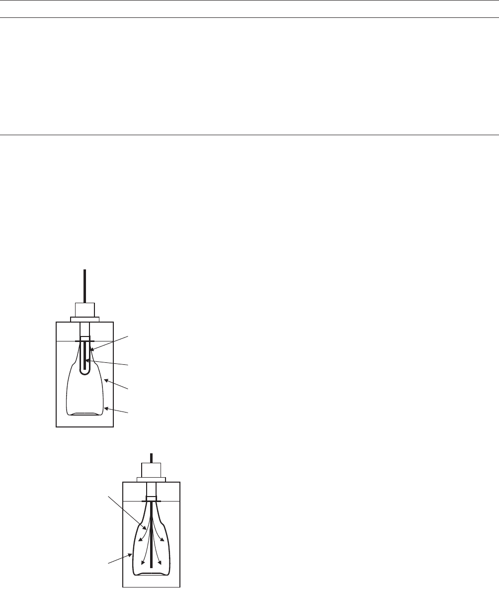
same length as the bottle is tall. The flow of air at elevated
pressure stretches the preform in a ‘‘hoop’’ direction—that
is, a direction substantially perpendicular to the preform’s
axis. At the same time, the flow of air, often in combination
with a stretch rod, stretches the preform in an axial
direction—that is, a direction parallel to the preform’s
axis. Needed air pressure is extreme; for example, PET
applications often require 600 PSI (4100 kPa) to properly
inflate the preform. In comparison, most extrusion blow-
molding applications require about 90 PSI (600 kPa).
There are two basic stretch-blow methods: one-step and
two-step. While at least one machinery builder has pro-
duced a one-step machine capable of producing a 20-L
container, most stretch-blow containers are less than 4 L
in capacity.
One-Step Method
Production stages of preform injection molding, heat con-
ditioning, and blow molding take place in the same
machine. Molding technicians generally consider it better
for manufacture of wide-mouth jars and better for bottles
having extreme oval or other unusual cross-sectional
shapes. The one-step method minimizes blemishes to
provide a pristine bottle-sidewall surface appearance. In
addition, the preform does not require a handling ring, as
the two-step method requires. Eliminating the handing
ring can improve the bottle’s overall aesthetic appearance.
Tooling and machinery setup is relatively easy, making
the method ideal for short-run production applications. In
addition, the method potentially saves energy in that the
preform does not require reheating from room tempera-
ture (see Figure 10).
On the other hand, one-step machinery typically has an
equal number of preform cavities and blow-mold cavities.
Dictated by specific preform and bottle shape, weight, and
performance requirements, rarely is an optimum process
or ideal production rate for preform molding stage in
perfect balance with that needed for bottle blow molding
stage. Accordingly, one process stage, usually preform
injection molding, will govern overall machine productiv-
ity while retarding productivity of the other process
stages. Sometimes process technicians are tempted to
make compromises, usually in preform configuration,
that reduce overall bottle performance in exchange for
greater overall production output.
There are three general variations of one-step machin-
ery. One variation features a four-station rotary table.
Preform injection molding in station one. Unlike injection
blow molding, the machine removes the preform core rod
before transfer to the next station. The preform is heat
Table 1. Injection Blow Molding Versus Extrusion Blow Molding
Injection Blow Molding Extrusion Blow Molding
Used for small, heavier bottles, typically less than 500 mL Used for larger bottles, typically larger than 250 mL
Best process for polystyrene; ideal for most other
thermoplastic materials
Best process for polyvinyl chloride; with adequate melt
strength, ideal for many other thermoplastic materials
Scrap-free: no flash/trim to recycle; no pinch-off scar on bottle;
no post-mold trimming required
Fewer bottle shape limitations permitting extreme
dimensional ratios: long and narrow, flat and wide, doubled-
walled, offset neck-finish, molded-in handle, and other odd
shapes
Injection-molded neck-finish provides more accurate neck-
finish dimensions that better address special shapes
required for complicated safety and tamper-evident closures
Precise and repeatable bottle weight control from injection-
molded perform
Low-cost tooling often made of aluminum; ideal for short- or
long-run manufacturing applications
Excellent and consistent bottle surface texture Adjustable weight control ideal for prototyping applications
Stretch Rod
Heated
Preform
Blow Mold
Bottle Cavity
(a)
Blow-Molded
Bottle
Action of
Stretch Rod
& High
Pressure Air
Flow
(b)
Figure 9. Basic stretch blow-molding process sequence: (a) Mold
close on preform; (b) stretch blow molding. Note that for many
PET applications, preform length is typically about one half the
bottle height.
146 BLOW MOLDING
conditioning in station two by heating and/or cooling
specific areas within the preform. Preform blow molding
into the bottle occurs in station three and bottle removal
occurs in station four. The second variation features a
three-station rotary table. Some machines combine pre-
form injection molding with heat conditioning in stage
one. Other machines combine bottle blow molding and
bottle removal in station three. The third variation com-
bines in one machine a substantially conventional preform
injection-mold tooling and apparatus with a substantially
conventional bottle blow-mold tooling and apparatus con-
nected by a preform transfer mechanism that includes a
short preform reheat oven. Preform injection-mold cavity
count is higher than bottle blow-mold cavity count, allow-
ing a more balanced operation.
Two-Step Method
Production stage of preform injection molding is separate,
taking place in a separate machine from heat conditioning
and bottle blow molding stage. Molding technicians often
refer to the two-step method as ‘‘reheat and blow.’’ The
method allows technicians to optimize preform and bottle
design and overall production efficiency. Equipment with
extremely high output is available. Figure 11 shows a high-
output PET preform injection-molding machine; although
not evident in the figure, these machines have a robotic
takeout that includes a post-mold cooling system. Figure 12
shows a typical high-output PET preform injection mold.
Figure 13 shows a high-output horizontal rotary bottle
stretch blow-molding machine with a preform oven for heat
conditioning. Bottle manufacturers often link a group of
injection molding machines producing the preform with a
group of blow-molding machines producing the bottle with
conveyors that reduce part handling and ‘‘work-in-process’’
inventory. Nonetheless, manufacture of the preform and
the bottle can be separate and in different facilities.
Molding technicians tend to use the two-step method
for containers having a substantially round cross-sec-
tional configuration; however, with improved reheat ovens
capable of heating regions within the preform to a differ-
ent temperature than other regions and precise preform
positioning in the blow-mold cavity, two-step machinery is
often suitable for containers having a substantially oval or
rectangular cross-sectional configuration.
MULTILAYER
All materials—whether metal, glass, paper, or plastic—
have certain strengths and weaknesses. Layering two or
more materials can economically overcome individual
material shortcomings. Multilayer blow molding is a way
to combine the strengths of two or more thermoplastic
materials to economically manufacture bottles that can
package a product far better than any of the materials
could individually. In recent years, multilayer structures
and related barrier polymers and machinery has
been an active development area within the blow-molding
industry, particularly for PET bottle applications. Ther-
moplastic materials in bottles now routinely protect sen-
sitive products previously not feasible.
Ideal characteristics of many bottles include: low cost,
strength, clarity, product compatibility, and gas barrier.
Polypropylene, for example, is a relatively low-cost mate-
rial suitable for food contact and having acceptable clarity,
Time
Temperature
Two-Step
Method
PET Material
Melting in Injection
Molding Machine
Break in Time
Melting Point
Crystalline PET
∼
∼
490°F (255°C)
Temperature
Maximum PET
Crystal Growth
∼
∼
350°F (177°C)
PET Glass
Transition
Temp. ∼
∼
180°F
(82°C)
Room
Temperature
PET Material Drying
in Heated Hopper
One-Step
Method
Preform Injection Molding
∼
∼
535°F (280°C)
Preform Reheat
Preform
Conditioning
Rapid Preform Cooling
Bottle
Cool
Bottle
Stretch Blo
w
Molding
Figure 10. Comparison of basic one-step and two-step
stretch blow-molding processes of PET.
BLOW MOLDING 147